Q6W838Car Alarm System
STEELMATE CO., LTD.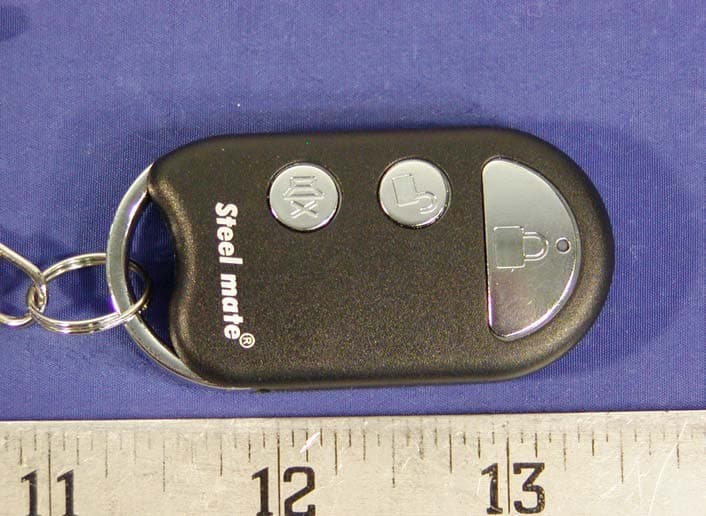
Click to zoom
Application Details
- Equipment Class
- DXX - Part 15 Low Power Communication Device Transmitter
- Date of Grant
- Sep 28, 2003
- Application Purpose
- Original Equipment
- Date of Application
- Sep 28, 2003
- Equipment Note
- Car Alarm System
- Frequency Range
- 433.92000000 - 433.92000000
- Company
- STEELMATE CO., LTD.
- Country
- China
Documents & Files
Document Text
Text extracted from the exhibit documents filed with the FCC. Open a document above to read the original.
Users Manual
1 838 CAR ALARM SYSTEM USER’S MANUAL INTRODUCTION Congratulations on your wise choice of Steel Mate Car Alarm System! Steelmate Co., Ltd. is a leading supplier to the automotive industry. We use our best endeavors to provide a range of highly innovative security and safety products to meet the needs of our customers. Through its innovative technology and best practice manufacturing facilities, Steelmate is (becoming) the market leader in China. Its high quality products, unique designs, and comprehensive after sales service ensure that Steelmate remains the first choice of Motor Vehicle Owners. Steelmate is not just a Brand... it is a culture ... a group of people striving to provide better and more efficient products in a rapidly changing world. It is a group of people who work hard, and stake their reputations on a successful outcome. With this kind of culture, with its expertise and with the customers needs firmly in mind, Steelmate is striving to be the Premier Brand in the vehicle market. Steelmate's expertise and experience will provide your vehicle with lifetime security. Thanks! 2 REMOTE FUNCTION AND OPERATOIN FOR MODEL 838 CAR ALARM SYSTEM FCC/ID Q6W838 FCC NOTICE: (b) For a Class B digital device or peripheral, the instructions furnished the user shall include the following or similar statement, placed in a prominent location in the text of the manual: Note: This equipment has been tested and found to comply with the limits for a Class B digital device, pursuant to part 15 of the FCC Rules. These limits are designed to provide reasonable protection against harmful interference in a residential installation. This equipment generates, uses and can radiate radio frequency energy and, if not installed and used in accordance with the instructions, may cause harmful interference to radio communications. However, there is no guarantee that interference will not occur in a particular installation. If this equipment does cause harmful interference to radio or television reception, which can be determined by turning the equipment off and on, the user is encouraged to try to correct the interference by one or more of the following measures: 3 -- Reorient or relocate the receiving antenna. -- Increase the separation between the equipment and receiver. -- Connect the equipment into an outlet on a circuit different from that to which the receiver is connected. -- Consult the dealer or an experienced radio/TV technician for help. Changes or modifications not expressly approved by the party responsible for compliance could void the user's authority to operate the equipment. To press button on the remote to activate the alarm system: Press button --- in general status: to arm the car and lock door in 3 seconds. --- in driving status: to lock door --- in alarm status: to stop alarm and return to the arm status. Press button --- in armed status: to disarm the car and unlock door. --- in driving status: to unlock door. --- in alarm status: to stop alarm, disarm the car and unlock door. Press button --- in general status: to arm the car with mute mode in 3 second, at 4 the same time, the indicators flash once. --- in driving status: to enter anti-robbery status for emergency alarm. unctions 1. Arming in alarm mode: Press button on the remote, the doors will be locked with a short chirp and a indicators flash, the LED light flashes slowly to indicate that the system is armed in alarm mode in 3 seconds. 2. Arming in mute mode: Press button on the remote to activate mute armed mode. The indicators flash once, and the LED light flashes slowly to indicate that the system will be armed in mute mode in 3 seconds. 3. Disarming In alarm mode, press button to disarm the system with two beeps and two indicators flashes. In mute mode, press button to disarm the system with two indicators flashes. 4. Auto central control door lock/unlock To press foot brake in 15 seconds after the car has been started, central control door lock will lock the door automatically for your safety during the driving. When the car stops, the door will be unlocked automatically. In driving status, press button to lock the doors or press buttonto unlock the doors. 5 5. Locating the car in a parking lot with sound and light To press button for 3 seconds, then the siren will beep for 2 seconds and the direction light will flash simultaneously to locate the car. 6. Emergency aid During your driving, press button , the siren will chirp for 15 seconds and the direction light will flash simultaneously for emergency aid. Press button to stop this function. 7. Anti-burglary and anti-hijacking (optional) In driving status, press button for 2 seconds ,the direction light will blink quickly, press button again to enter the anti-hijacking mode. The siren will chirp sharply. 8. Remote trunk release To Press button for 3.5 seconds to open trunk with remote controller. CONTROL UNIT FUNCTION AND OPERATOIN FOR MODEL 838 6 CAR ALRM SYSTEM FCC NOTICE: (b) For a Class B digital device or peripheral, the instructions furnished the user shall include the following or similar statement, placed in a prominent location in the text of the manual: Note: This equipment has been tested and found to comply with the limits for a Class B digital device, pursuant to part 15 of the FCC Rules. These limits are designed to provide reasonable protection against harmful interference in a residential installation. This equipment generates, uses and can radiate radio frequency energy and, if not installed and used in accordance with the instructions, may cause harmful interference to radio communications. However, there is no guarantee that interference will not occur in a particular installation. If this equipment does cause harmful interference to radio or television reception, which can be determined by turning the equipment off and on, the user is encouraged to try to correct the interference by one or more of the following measures: -- Reorient or relocate the receiving…
Text truncated - open the document above for the full version.
External Photos
External Photos EUT-Top View EUT-Rear View
ID Label/Location Info
ID Label Label FCC ID: Q6W838
ID Label/Location Info
ID Label/Location Label Location Information Specifications: Text is Black or white in color and is left justified. Labels are printed in indelible ink on permanent adhesive backing or silk-screened onto the EUT or shall be affixed at a conspicuous location on the EUT. Refer to the below arrow. Label Location of Handset
Internal Photos
Internal Photos EUT Component View EUT Solder View
Operational Description
Model 838 car alarm system Circuit Description T1063TA Circuit Description The transmitter section of the T1063TA oscillated circuit consists of Oscillator Q1, Y1, C1, C2, and C3. The 12V cell supply’s energy to couple out to oscillated circuit via K switch (K1, K2, K3) to the diode D (D1, D2, D3), to the output tank L1. Amplitude modulation signal is emitted by U1, accomplished via R7 to the oscillated circuit, and emit with the PCB's copper trace antenna (the antenna is between the Q1 and L1).
Operational Description
838 Car Alarm System Description and Specification Function description: 1 Remote control arming/disarming 2 Engine immobilization 3 Alarm armed mode 4 Mute armed mode 5 Anti-jamming 6 Auto re-arming 7 Anti-hijacking 8 Code learning 9 Emergency alarm 10 Warning for unlocked vehicle 11 Warning for disarmed vehicle 12 Locating with sound and light 13 Remote trunk release 14 Emergency override 15 Automatic lock/unlock 16 Trigger memory and report Technical Information: 1. Control box Voltage: 12V±2V Static current: <20mA LED current: 5~10mA Siren current: <1mA Output Current (max): direction indicator: 5A×2 Siren: 5A Door lock: 10A Frequency: 433.92MHz Power: <10mW 2. Remote controller Voltage: 12V±2V Static current: 400uA Battery size: AAA Frequency: 433.92MHz Power: <10mW 3. Siren Volume: 105~110DB Power: 15W
Test Report
Note: This test report is specially limited to the above client company and product model only. It may not be duplicated without prior written consent of Bay Area Compliance Laboratory Corporation. This report must not be used by the client to claim product endorsement by NVLAP or any agency of the U.S. Government. FCC PART 15 SUBPART C EMI MEASUREMENT AND TEST REPORT For STEELMATE CO., LTD Guanghong, Lianhe, Beijiao, Xinshi Town, Baiyun District, Guangzhou 510425, China FCC ID: Q6W838 2003-08-12 This Report Concerns: Original Report Equipment Type: Car Alarm System Test Engineer:Jerry Wang / Report No.:R0302282 Test Date:2003-08-01 Reviewed By: Ling Zhang Prepared By:Bay Area Compliance Laboratory Corporation (BACL) 230 Commercial Street Sunnyvale, CA 94085 Tel: (408) 732-9162 Fax: (408) 732-9164 STEELMATE CO., LTD FCC ID: Q6W838 Report # R0302282Page 2 of 11FCC ID Per 15.231 Report TABLE OF CONTENTS 1 - GENERAL INFORMATION.................................................................................................................................................3 1.1 PRODUCT DESCRIPTION FOR EQUIPMENT UNDER TEST (EUT).........................................................................................3 1.2 OBJECTIVE................................................................................................................................................................................3 1.3 RELATED SUBMITTAL(S)/GRANT(S)......................................................................................................................................3 1.4 TEST METHODOLOGY.............................................................................................................................................................3 1.5 TEST FACILITY.........................................................................................................................................................................3 1.6 TEST EQUIPMENT LIST............................................................................................................................................................4 2 - SYSTEM TEST CONFIGURATION..................................................................................................................................5 2.1 JUSTIFICATION.........................................................................................................................................................................5 2.2 BLOCK DIAGRAM.....................................................................................................................................................................5 2.3 EQUIPMENT MODIFICATIONS.................................................................................................................................................5 2.4 CONFIGURATION OF TEST SYSTEM.......................................................................................................................................5 3 - SUMMARY OF TEST RESULTS........................................................................................................................................6 4 - AC LINE CONDUCTED EMISSIONS...............................................................................................................................7 5 - RADIATED EMISSION DATA............................................................................................................................................8 5.1 EUT SETUP...............................................................................................................................................................................8 5.2 SPECTRUM ANALYZER SETUP...............................................................................................................................................8 5.3 TEST PROCEDURE....................................................................................................................................................................8 5.4 CORRECTED AMPLITUDE & MARGIN CALCULATION........................................................................................................8 5.5 EQUIPMENT LIST......................................................................................................................................................................8 5.5 TEST RESULTS..........................................................................................................................................................................9 6 - 20DB BANDWIDTH...............................................................................................................................................................10 6.1 REQUIREMENT.......................................................................................................................................................................10 6.2 EQUIPMENT LIST....................................................................................................................................................................10 6.3 TEST RESULT..........................................................................................................................................................................10 7 - DEACTIVATION....................................................................................................................................................................11 7.1 REQUIREMENT.......................................................................................................................................................................11 7.2 TEST EQUIPMENT..................................................................................................................................................................11 7.3 TEST RESULT.......................................................................................................................…
Text truncated - open the document above for the full version.
Test Setup Photos
Test Setup Photos Radiated Emission of Transmitter– Front View Radiated Emission of Transmitter– Rear View Radiated Emission of Transmitter– Close View
Contact Information
Applicant
Ben Fang(Engineer)
Test Firm
Bay Area Compliance LaboratoryJohn Chan
Technical Specifications
| # | Rule Parts | Frequency Range | Power Output |
|---|---|---|---|
| 1 | 15C | 433.92 MHz - 433.92 MHz | - |
Other Applications from STEELMATE CO., LTD.
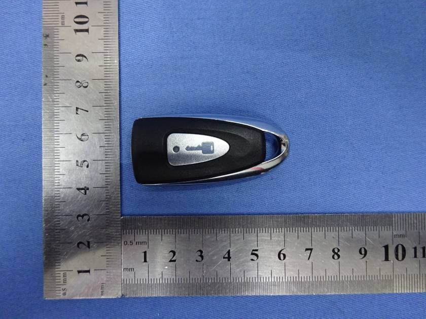
Q6WBT1011A
Oct 24, 2015Transmitter
Equipment Class
DSC - Part 15 Security/Remote Control Transmitter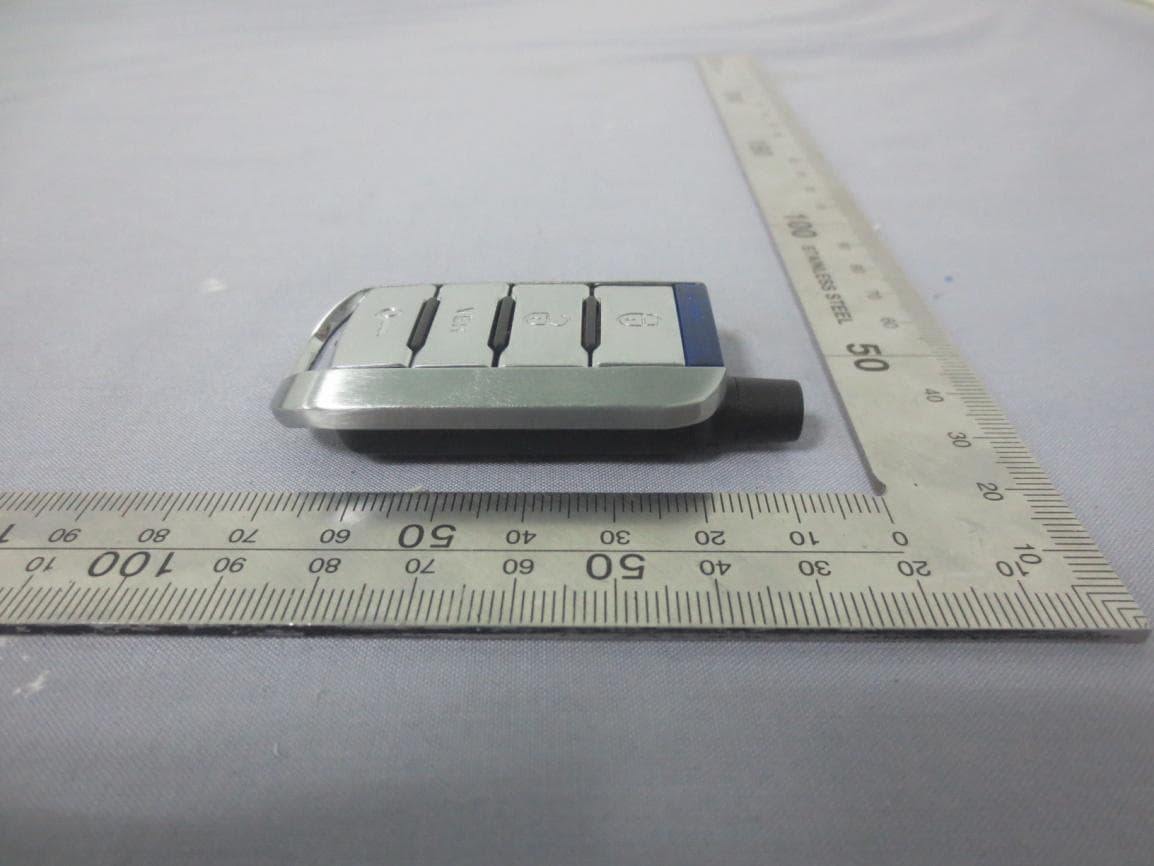
Q6WBT4312A
Aug 07, 2015Transmitter
Equipment Class
DSC - Part 15 Security/Remote Control Transmitter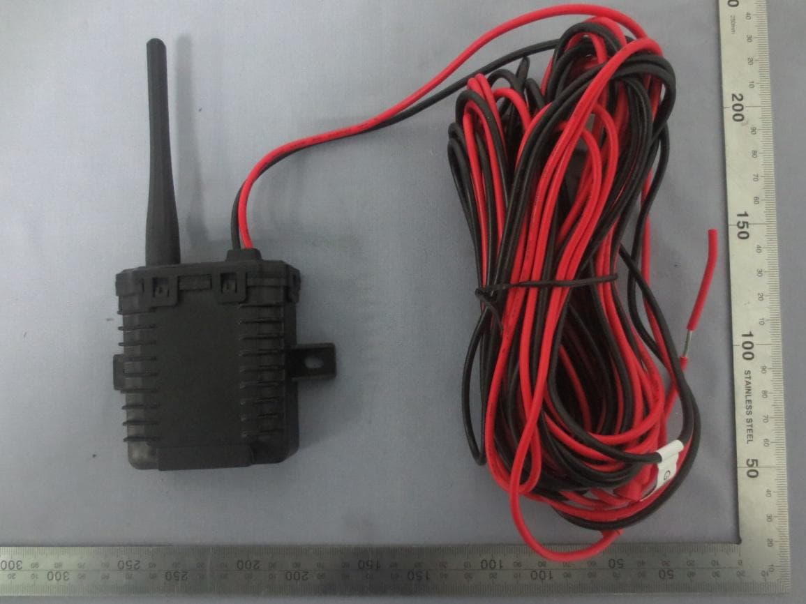
Q6WBTP141
Feb 08, 2015TPMS
Equipment Class
DSC - Part 15 Security/Remote Control Transmitter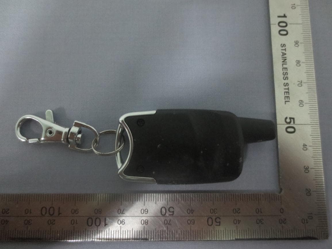
Q6WBT5161
Sep 05, 2014Transmitter
Equipment Class
DSC - Part 15 Security/Remote Control Transmitter
Q6WBT5162
Sep 05, 2014Transmitter
Equipment Class
DSC - Part 15 Security/Remote Control Transmitter