Q6WBRM054Wireless Parking Sensor System
STEELMATE CO., LTD.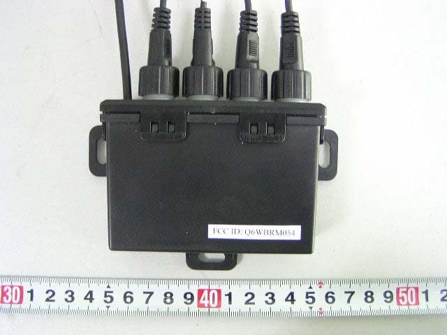
Click to zoom
Application Details
- Equipment Class
- DXX - Part 15 Low Power Communication Device Transmitter
- Date of Grant
- Nov 14, 2005
- Application Purpose
- Original Equipment
- Date of Application
- Nov 14, 2005
- Equipment Note
- Wireless Parking Sensor System
- Frequency Range
- 27.04500000 - 27.04500000
- Company
- STEELMATE CO., LTD.
- Country
- China
Documents & Files
Document Text
Text extracted from the exhibit documents filed with the FCC. Open a document above to read the original.
Users Manual
PRI0023/A Registration Details This form must be filled in, kept handy and produced with any warranty claim, together with the purchase invoice and/or receipt. Think about safety Think Steel mate MODEL : PTS400Q PARKING ASSISTANT SYSTEM MANUFACTURED BY: Steelmate Co., Ltd. http: //www.globalsources.com/steelmate.co E-mail: [email protected] [email protected] Manual ISO 9001 : 2000 Certiticate : 04111 2003 1786 ISO / TS 16949 : 2002 Certiticate : 04111 2003 1786 Name: Address: Authorized Dealer: Purchase Date: Vehicle Type: Registration No: Installers' Name: Product Type: Model No: < 0.4m, Zone 5 (Red LED) 0.4~0.6m, Zone 4 (Red LED) 0.6~0.8m, Zone 3 (Orange LED) 0.8~1.0m, Zone 2 (Orange LED) 1.0~1.7m, Zone 1 (Green LED) The Digital Matrix LED Display: example 2example 1 example 3 Attentions Misleading detection may occour due to the following cases: Smooth sloping surfaceSmooth round objectItems absorbing sound,e.g.cotton 1.Heavy raln,dirty or damaged sensor could result in mlsleading detection. 2.Check if the system is in order before use. 3.Please replace the damaged sensor when the system detects it. 4.The product is a driver assistant device. No warranty as to operating efficiency and accident is guaranteed. It is not a substitute for the driver's responsibility when driving a vehicle. 5.Do not paint over the sensors as this will affect the performance. 2 9 Volume switch The digital number on display will show every 0.1M change of distance Digital Number Display + Audio Warning Audio warningDistance on displayLED matrix display 4 Mount the display on the dashboard firmly for the driver easy to see. Clean the dash board for mouting the display. Take off the 3M sticker of the display. Display Installation 7 black white GND 2P Reversing power(+) Zone 1 Zone 2Zone 3 Zone 4Zone 5 Zone 5 The parking assistant system is an ultrasonic distance monitoring system. It electronically detects the area behind your vehicle during reversing, and alerts you with audible tone and digital display if there is an object behind your car. Every piece of our products has passed the most stringent test before releasing to the market. It is reliable at a wide temperature range ( -40ûC ~ +80ûC) and becomes very useful when you are reversing at a raining day, snowing day or at night etc. With the help of Steelmate parking assistant system, you can enjoy a convenient and nervous - free reversing. Features: 1. Detection distance: 0.30 ~ 1.79 m 2. No wire from ECU to display 3. Self-test function activated by reverse gear 4. 3 Colour matrix LED display shows the object's location 5. Anti-false alert technology 6. All weather design (-40ûC ~ +80ûC) 7. Easy installation 8. Volume control Specifications: a) Voltage: 12 V*3V b) ECU working current: 35mA*5mA c) Display working current: < 270mA d) Buzzer: 70 ~ 90dB Possible Causes And Solutions I. The unit is warranted for a limited period from the date of purchase. In the event of any defect arising in the unit when you use it as per the instructions during the warranty period, the repair would be carried out free. * It is required to show this Warranty Card when have the unit repaired. * The model and series number on unit must be the same as the information in the Warranty Card. II. This warranty is non-transferable and is automatically void if: * The original purchaser has not completed the warranty card * The unit's serial number is defaced, missing or altered * The unit has been modified or used in a manner contrary to its intended purpose * The unit has been damaged by accident, unreasonable use, neglect, improper service and installation. III. The warranty does not cover damage to the unit caused by installation or removal of the unit. Warranty 10 1 About Parking Assistant System (PTS) Important Notice This parking assistant system is designed as a reversing aid. It is not a substitute of driver's responsibilities normally assumed when reversing. Steelmate does not liable for any damages caused by reversing only rely on this system. Proper driving skills, such as slow down, use of mirror or lookout etc. is always essential. 1. This unit is for vehicles with 12v DC only 2. It should be installed by a professional 3. Avoid high temperature and high voltage while laying out the wire harness 4. Wire connection point should be insulated 5. Conduct test after finishing the installation 1. No beep at power up or no LED light falshing 1).Is power wire connected to ECU correctly? 2).Verify the ground connection 3).Have you connected theÊcorrect reversing light wire? Ê 2. False warning tone or false LED falshing 1).Is sensor mounted too low or pointing to the ground? Ê 3.Sensors do not detect any objects 1).Are sensors properly plugged into the correct sockets? Ê If the problem persists, please follow these steps: A. For consumers: Contact your dealer or nearby steelmate service center B. For Installer or dealer: 1).Replace the ECU and re-check the system 2).Test the sensors withÊcertified ECU and using a flat wooden board 3).Plug the certified sensors into the ECU and re-check 4).Email your questions and we will reply ASAP. Ê More tech tips are available on our website: www.steel-mate.com The system will test all the sensors when the reversing gear is engaged. If all the sensors are normal, the system will beep once and the LED display will flash once. If there is any problem with the sensors, the system will beep three times to indicate that one or more sensors have problems. Self-test Function The flashing LED indicates the problem sensor The total number of the problem sensors Sensor A has problem (E1: 1 problem sensor) Sensor A,D have problem (E2: 2 problem sensors) *Check the problem sensor or replace the damaged sensor. The system will test all the sensors when the reversing gear is engaged, and then the system detects objects. a) The object distance is: >1.8m: b) The object distance is: 1.7~0.3m: The display will show the distance by digital number and…
Text truncated - open the document above for the full version.
External Photos
External Photos EUT-Full View EUT-Front View EUT-Rear View
ID Label/Location Info
ID Label Label
ID Label/Location Info
ID Label/Location Label Location Information Specifications: Text is Black or white in color and is left justified. Labels are printed in indelible ink on permanent adhesive backing or silk-screened onto the EUT or shall be affixed at a conspicuous location on the EUT. Label Location
Internal Photos
Internal Photos EUT-Inside View EUT- PCB View (1) EUT- PCB View (2)
Test Report
Note: The test report is specially limited to the above company and this particular sample only. It may not be duplicated without prior written consent of Bay Area Compliance Lab Corp. (ShenZhen). This report must not be used by the client to claim product certification, approval, or endorsement by NVLAP, NIST or any agency of the US Government. FCC PART 15.227 EMI MEASUREMENT AND TEST REPORT For Steelmate Co., Ltd. Renan Street, Dongfu Road, Dongfeng Town, Zhongshan, 528425, China FCC ID: Q6WBRM054 November 14, 2005 This Report Concerns: Original Report Equipment Type: Wireless parking sensor system Test Engineer: William Chan Simon Mo Report No.: RSZ05110301 Test Date: November 8-14, 2005 Reviewed By: Chris Zeng Prepared By: Bay Area Compliance Lab Corp. (ShenZhen) 6/F, the 3rd Phase of WanLi Industrial Building, ShiHua Road, FuTian Free Trade Zone, ShenZhen, Guangdong 518038, P.R.China Tel: +86-755-33320018 Fax: +86-755-33320008 Steelmate Co., Ltd. FCC ID: Q6WBRM054 Report # RSZ05110301 Page 2 of 14 FCC PART 15.227 Report TABLE OF CONTENTS GENERAL INFORMATION.......................................................................................................................................3 PRODUCT DESCRIPTION FOR EQUIPMENT UNDER TEST (EUT) ....................................................................................3 OBJECTIVE...................................................................................................................................................................3 RELATED SUBMITTAL(S)/GRANT(S).............................................................................................................................3 TEST METHODOLOGY..................................................................................................................................................3 TEST FACILITY.............................................................................................................................................................3 EXTERNAL I/O CABLE.................................................................................................................................................4 SYSTEM TEST CONFIGURATION ..........................................................................................................................5 JUSTIFICATION.............................................................................................................................................................5 EQUIPMENT MODIFICATIONS.......................................................................................................................................5 CONFIGURATION OF TEST SETUP.................................................................................................................................5 BLOCK DIAGRAM OF TEST SETUP................................................................................................................................5 SUMMARY OF TEST RESULTS...............................................................................................................................6 §15.203 - ANTENNA REQUIREMENT......................................................................................................................7 STANDARD APPLICABLE..............................................................................................................................................7 §15.205, §15.209, §15.227(A) - RADIATED EMISSIONS TEST ..............................................................................8 MEASUREMENT UNCERTAINTY....................................................................................................................................8 EUT SETUP..................................................................................................................................................................8 EMI TEST RECEIVER SETUP........................................................................................................................................8 TEST EQUIPMENT LIST AND DETAILS...........................................................................................................................9 CORRECTED AMPLITUDE & MARGIN CALCULATION...................................................................................................9 TEST RESULTS SUMMARY............................................................................................................................................9 TEST DATA................................................................................................................................................................10 PLOT(S) OF TEST DATA..............................................................................................................................................10 §15.227(B) - OUT OF BAND EMISSION .................................................................................................................13 T EST E QUIPMENT L IST AND D ETAILS .........................................................................................................................13 T EST P ROCEDURE ......................................................................................................................................................13 TEST DATA................................................................................................................................................................13 Steelmate Co., Ltd. FCC ID: Q6WBRM054 Report # RSZ05110301 Page 3 of 14 FCC PART 15.227 Report GENERAL INFORMATION Product Description for Equipment Under Test (EUT) The Steelmate Co., Ltd.’s product, model number: PTS400Q-COM or the "EUT" as referred to in this report is a Wireless parking sensor system. The EUT is measured approximately 9.8 cm L x 6.5 cm W x 2.5 cm H. rated input voltage: DC 12V battery. Battery: Manufacturer: Hua yang, Model: 6-DZM-10. * The test data gather…
Text truncated - open the document above for the full version.
Test Setup Photos
Test Setup Photos Radiated Emissions-Front View Radiated Emissions-Rear View
Contact Information
Applicant
Ben Fang(Engineer)
Test Firm
Bay Area Compliance Laboratory Corp. (Shenzhen)John Chan
Technical Specifications
| # | Rule Parts | Frequency Range | Power Output |
|---|---|---|---|
| 1 | 15C | 27.045 MHz - 27.045 MHz | - |
Other Applications from STEELMATE CO., LTD.
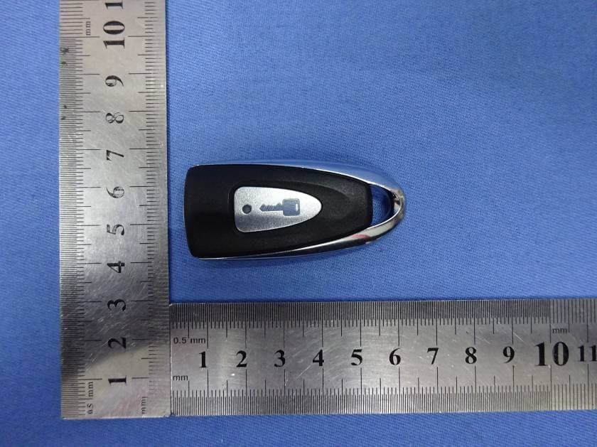
Q6WBT1011A
Oct 24, 2015Transmitter
Equipment Class
DSC - Part 15 Security/Remote Control Transmitter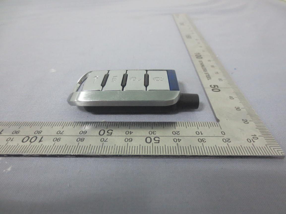
Q6WBT4312A
Aug 07, 2015Transmitter
Equipment Class
DSC - Part 15 Security/Remote Control Transmitter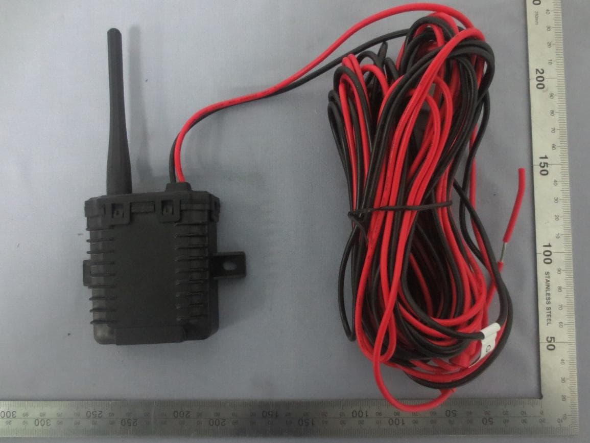
Q6WBTP141
Feb 08, 2015TPMS
Equipment Class
DSC - Part 15 Security/Remote Control Transmitter
Q6WBT5161
Sep 05, 2014Transmitter
Equipment Class
DSC - Part 15 Security/Remote Control Transmitter
Q6WBT5162
Sep 05, 2014Transmitter
Equipment Class
DSC - Part 15 Security/Remote Control Transmitter