Q6WBT4123SINGLE-WAY TRANSMITTER
STEELMATE CO., LTD.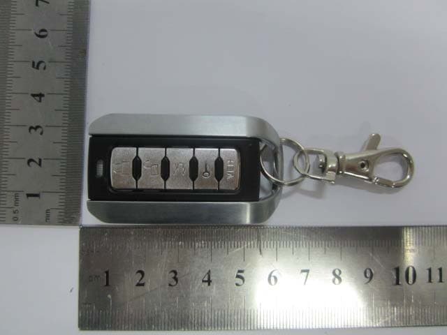
Click to zoom
Application Details
- Equipment Class
- DSC - Part 15 Security/Remote Control Transmitter
- Date of Grant
- Nov 06, 2011
- Application Purpose
- Original Equipment
- Date of Application
- Nov 06, 2011
- Equipment Note
- SINGLE-WAY TRANSMITTER
- Frequency Range
- 433.92000000 - 433.92000000
- Company
- STEELMATE CO., LTD.
- Country
- China
Documents & Files
Document Text
Text extracted from the exhibit documents filed with the FCC. Open a document above to read the original.
Users Manual
PS03-G3 and PS04-G3 1 WAY REMOTE START SYSTEM OPERATING INSTRUCTIONS CONGRATULATIONS on your choice of a Fortress PRO Start™ Remote Engine Starter and Keyless Entry with DP Technology by Crimestopper Security Products Inc. This booklet contains the information necessary for operating your system. If any questions arise, contact your installation dealer or Crimestopper Security Products Inc. *IMPORTANT INFORMATION: Primary and Optional Features -PRIMARY: These are features that must be connected in order for the system to operate properly i.e. Remote Start connections, Flashing lights, and Brake Reset. For programming, the hood pin and program button are required. -OPTIONAL: These features are to be connected only if desired or agreed upon by the customer and the installing dealer i.e. Door Locks, Horn-Honk, Anti-Grind, etc. These features may also require additional parts and/or labor fees. Consult with your installer beforehand to be sure of what is going to be installed with your particular system. REV 06-2011 This device complies with FCC Rules part 15. Operation is subject to the following two conditions: 1) This device may not cause interference, and (2) this device must accept any interference that may be received, including interference that may cause undesired operation. The manufacturer is not responsible for any changes or modifications not expressly approved by manufacturer for compliance. Such modification could void the user's authority to operate the equipment. 2 TABLE OF CONTENTS Operation Cautions & Warnings.......................................................................................................2 Using the Remote Transmitter.........................................................................................................3 Status LED.................................................................................................................................4 Remote Engine Control...............................................................................................................4-7 Turbo Timer Mode........................................................................................................................8 Manual Transmission Mode............................................................................................................9 Convenience and Safety Features................................................................................................9-11 Transmitter Programming..............................................................................................................12 2 Vehicle Operation.....................................................................................................................13 No Factory Keyless Entry after Remote Start....................................................................................14 Remote Start Diagnostics.............................................................................................................14 Battery Replacement....................................................................................................................15 2-Way Data Port........................................................................................................................16 OPERATION CAUTIONS & WARNINGS CRIMESTOPPER SECURITY PRODUCTS, INC. and its VENDORS shall not be liable for any accident resulting from the use of this equipment. This system is designed to be professionally installed into a car or vehicle in which all items, such as parking brake and all associated components, door switches, transmission shift linkage, throttle linkage, and all engine safety features, are in perfect working condition. IT IS ABSOLUTELY THE OWNER’S SOLE RESPONSIBILITY TO: A) Understand the operation of this system and its safety features. B) Check for proper operation of the system prior to accepting delivery of the vehicle from the installation facility. C) Check and maintain the condition of the vehicle and all items relative to the proper operation of this system and its safety features. D) Always leave the doors and windows closed and locked to protect against accidents and theft. DO NOT remote start the vehicle in a closed garage. Make sure that the garage door is open or there is adequate ventilation. Failure to observe this rule could result in injury or death from poisonous Carbon Monoxide fumes. 3 USING THE REMOTE TRANSMITTER VEH VEH For PS03-G3 The transmitter supplied with this system has 4 vertical buttons – Lock, Unlock, Start and Vehicle Select. The button configuration is Factory-set and unchangeable. See Page 13 for additional information on how to use your remote to operate a second vehicle equipped with a PS03-G3 series system. For PS04-G3 The transmitter supplied with this system has 5 vertical buttons – Lock, Unlock, Trunk Release, Start and Vehicle Select. The button configuration is Factory-set and unchangeable. See Page 13 for additional information on how to use your remote to operate a second vehicle equipped with a PS04-G3 series system. 4 STATUS LED STATUS LED: Used for Remote Start Diagnostics – page 14 (Optional, requires Installation of LED) LED will flash when locking your doors with remote. LED will remain solid in Valet Service Mode. REMOTE ENGINE CONTROL REMOTE START & TRUNK POP – Button Press Selection (Option # 6): To eliminate the possibility of accidentally opening the trunk or starting the vehicle, there are (3) options for button press selection. This option will allow you to change whether the Remote starter and Trunk release activate by a: 1. Double button - ½ second presses. 2. *Single ½ second press (Default). 3. Press and Hold 2 seconds. *Default = 1 single press & release* REMOTE ENGINE STARTING – SUCCESSFUL START: 1) Press the remote start button for at least ½ second (*default). Parking lights flash once, return solid, and the Ignition/Acc circuits turn on. 2) After a few seconds the Starter Motor engag…
Text truncated - open the document above for the full version.
External Photos
GUANGDONG STEELMATE SECURITY CO., LTD. Model: RS-3 REPORT NO.: STR11108148I FCC PART 15.231 EXHIBIT 2 - EUT EXTERNAL PHOTOGRAPHS EUT View 1 EUT View 2
ID Label/Location Info
GUANGDONG STEELMATE SECURITY CO., LTD. Model: RS-3 REPORT NO.: STR11108148I FCC PART 15.231 EXHIBIT 1- PRODUCT LABELING Proposed FCC ID Label Format FCC ID: Q6WBT4123 Specifications : Text is Black in color and justified. Labels are printed in indelible ink on permanent adhesive silk-screened onto the EUT or shall be affixed at a conspicuous location on the EUT. Proposed Label Location on EUT FCC ID Label Location
Internal Photos
GUANGDONG STEELMATE SECURITY CO., LTD. Model: RS-3 REPORT NO.: STR11108148I FCC PART 15.231 EXHIBIT 3 - EUT INTERNAL PHOTOGRAPHS EUT Housing and Board View Solder Board-Component View 1 GUANGDONG STEELMATE SECURITY CO., LTD. Model: RS-3 REPORT NO.: STR11108148I FCC PART 15.231 Solder Board-Component View 2
Operational Description
BATTERY:power supplyer BUTTON:press the key to control the ECU to input the date LED:indicate the working mode MCU:receive and send the date 4.00MHz CRYSTAL:provide the reference clock for the MCU RF IC:modulate MCU output date,amplify the high-frequency signal and send it to the next stage amplify RF Amplifier:Amplify high-frequency signal of 433.92MHz MATCHING CIRCUIT:modulate RF IC output impedance,made it matching with the antenna network to output maximal power
Schematics
NO: CHK TITLE: DATE REV PAG APP DRAWN ×¢£º4¼üÒ£¿ØÆ÷ʱ£¬S5Ϊ¿Õ¡£ D2 RED 1 P0.1 2 P1.2 3 P1.3 4 P0.0 5 P1.5 6 VSS 7 P5.0 8 P5.1 20 P1.7 19 P1.1 18 P1.0 17 XIN 16 XOUT 15 VDD 14 P5.7 13 P5.6 9 P5.2 10 P5.3 12 P5.5 11 P5.4 U2 R1 5.1K X3 4MHZ C3 20P C4 20P C11 103 D1 green S2 DISARM S1 ARM S5 VEH S3 TRUNK S4 START R7 100K R8 5.1K R2 1K C2 18P 1 PA 2 VSS 3 VDD 4 XTLO 5 XTLI 6 ASK U1 X1 13.56MHz C5 18P C6 18P L1 33nH L2 10P C7 47nH BAT1 2016*3 R3 10K C8 10U/6V C9 104 Q1 M6 Q2 H7D R5 270R L3 100nH R6 20R C10 103 L4 33nH C12 10P C1 NC IN GND OUT Q3 MD5350 C13 106 R9 0R VDD VCC_CTL VDD VCC VCC VCC_CTL VCC VDD VDD
Test Report
GUANGDONG STEELMATE SECURITY CO., LTD. Model: RS-3 REPORT NO.: STR11108148I PAGE 1 OF 17 FCC PART 15.231 FCC PART 15.231 MEASUREMENT AND TEST REPORT FOR GUANGDONG STEELMATE SECURITY CO., LTD. Renan Street, Dongfu Road, Dongfeng Town, Zhongshan, 528425, China FCC ID: Q6WBT4123 Report Concerns: Original Report Equipment Type: Single-way Transmitter Model: RS-3 Report No.: STR11108148I Test Date: 2011-10-21 to 2011-11-03 Issue Date: 2011-11-07 Tested By: Silin Chen / Engineer Reviewed By: Lahm Peng / EMC Manager Approved & Authorized By: Jandy so / PSQ Manager Prepared By: SEM.Test Compliance Service Co., Ltd 3/F, Jinbao Commerce Building, Xin'an Fanshen Road, Bao'an District, Shenzhen, P.R.C.(518101) Tel.: +86-755-33663308 Fax.: +86-755-33663309 Website: www.semtest.com.cn Note: This test report is limited to the above client company and the product model only. It may not be duplicated without prior permitted by SEM.Test Compliance Service Co., Ltd . GUANGDONG STEELMATE SECURITY CO., LTD. Model: RS-3 REPORT NO.: STR11108148I PAGE 2 OF 17 FCC PART 15.231 TABLE OF CONTENTS 1. GENERAL INFORMATION ...................................................................................................................................3 1.1 PRODUCT DESCRIPTION FOR EQUIPMENT UNDER TEST (EUT)...............................................................................3 1.2 TEST STANDARDS...................................................................................................................................................3 1.3 TEST METHODOLOGY.............................................................................................................................................4 1.4 TEST FACILITY.......................................................................................................................................................4 1.5 EUT EXERCISE SOFTWARE....................................................................................................................................4 1.6 ACCESSORIES EQUIPMENT LIST AND DETAILS.......................................................................................................4 1.7 EUT CABLE LIST AND DETAILS.............................................................................................................................4 2. SUMMARY OF TEST RESULTS ...........................................................................................................................5 3. §15.203 ANTENNA REQUIREMENT ....................................................................................................................6 3.1 STANDARD APPLICABLE.........................................................................................................................................6 3.2 TEST RESULT..........................................................................................................................................................6 4. §15.205, §15.209, §15.231 (B) RADIATED EMISSION .........................................................................................7 4.1 MEASUREMENT UNCERTAINTY..............................................................................................................................7 4.2 STANDARD APPLICABLE.........................................................................................................................................7 4.3 TEST EQUIPMENT LIST AND DETAILS.....................................................................................................................8 4.4 TEST PROCEDURE...................................................................................................................................................8 4.5 CORRECTED AMPLITUDE & MARGIN CALCULATION..............................................................................................9 4.6 ENVIRONMENTAL CONDITIONS..............................................................................................................................9 4.7 SUMMARY OF TEST RESULTS/PLOTS......................................................................................................................9 5. §15.231(C) 20DB BANDWIDTH TESTING .........................................................................................................12 5.1 STANDARD APPLICABLE.......................................................................................................................................12 5.2 TEST EQUIPMENT LIST AND DETAILS...................................................................................................................12 5.3 TEST PROCEDURE.................................................................................................................................................12 5.4 ENVIRONMENTAL CONDITIONS............................................................................................................................12 5.5 SUMMARY OF TEST RESULTS/PLOTS....................................................................................................................12 6. §15.231(A) DEACTIVATION TESTING..............................................................................................................14 6.1 STANDARD APPLICABLE.......................................................................................................................................14 6.2 TEST EQUIPMENT LIST AND DETAILS...................................................................................................................14 6.3 TEST PROCEDURE.................................................................................................................................................14 6.4 ENVIRONMENTAL CONDITIONS............................................................................................................................14 6.5 SUMMARY OF TEST RESULTS/PLOTS..................................................…
Text truncated - open the document above for the full version.
Test Setup Photos
GUANGDONG STEELMATE SECURITY CO., LTD. Model: RS-3 REPORT NO.: STR11108148I FCC PART 15.231 EXHIBIT 4 - TEST SETUP PHOTOGRAPHS Radiation Emission Test Setup (Below 30MHz) Radiation Emission Test Setup (30MHz to 1GHz) GUANGDONG STEELMATE SECURITY CO., LTD. Model: RS-3 REPORT NO.: STR11108148I FCC PART 15.231 Radiation Emission Test Setup (Above 1GHz)
Contact Information
Applicant
Ben Fang(Engineer)
Test Firm
SEM.Test Compliance Service Co., Ltd.Jandy So
Technical Specifications
| # | Rule Parts | Frequency Range | Power Output |
|---|---|---|---|
| 1 | 15.231 | 433.92 MHz - 433.92 MHz | - |
Other Applications from STEELMATE CO., LTD.
Q6WBT1011A
Oct 24, 2015Transmitter
Equipment Class
DSC - Part 15 Security/Remote Control Transmitter
Q6WBT4312A
Aug 07, 2015Transmitter
Equipment Class
DSC - Part 15 Security/Remote Control Transmitter
Q6WBTP141
Feb 08, 2015TPMS
Equipment Class
DSC - Part 15 Security/Remote Control Transmitter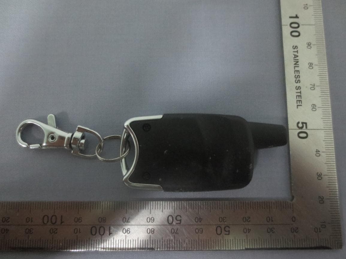
Q6WBT5161
Sep 05, 2014Transmitter
Equipment Class
DSC - Part 15 Security/Remote Control Transmitter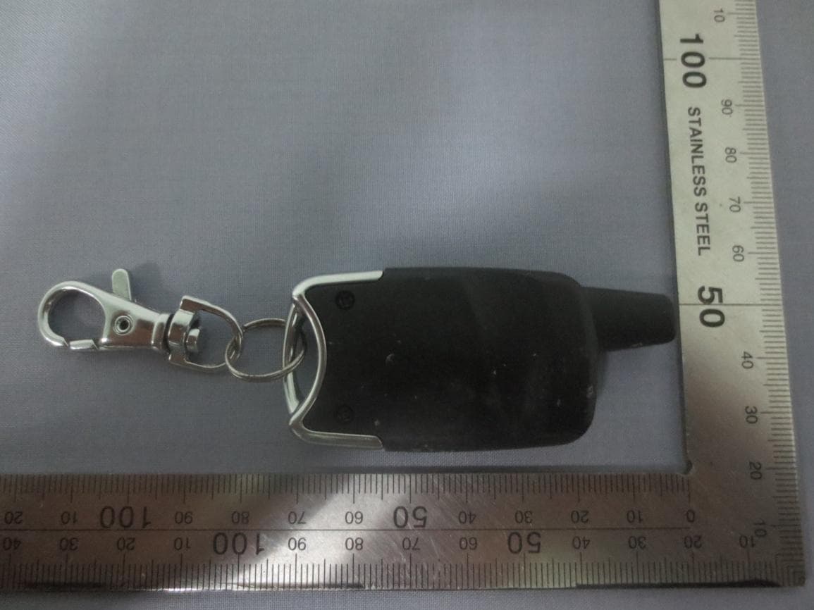
Q6WBT5162
Sep 05, 2014Transmitter
Equipment Class
DSC - Part 15 Security/Remote Control Transmitter