Q77CMSSECURITY CAMERA
Beyond Broadband Network, Inc.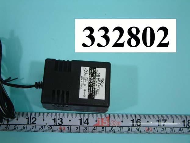
Click to zoom
Application Details
- Equipment Class
- DXX - Part 15 Low Power Communication Device Transmitter
- Date of Grant
- Jul 22, 2003
- Application Purpose
- Original Equipment
- Date of Application
- Jul 22, 2003
- Equipment Note
- SECURITY CAMERA
- Frequency Range
- 2410.00000000 - 2470.00000000
- Country
- Taiwan
Documents & Files
Document Text
Text extracted from the exhibit documents filed with the FCC. Open a document above to read the original.
External Photos
FCC ID: Q77CMS NUMBER 1 FRONT SIDE OF EUT FCC ID: Q77CMS NUMBER 2 REAR SIDE OF EUT FCC ID: Q77CMS NUMBER 3 REAR SIDE OF ADAPTOR FCC ID: Q77CMS NUMBER 4 REAR SIDE OF ADAPTOR FCC ID: Q77CMS NUMBER 5 FRONT SIDE OF ADAPTOR
ID Label/Location Info
FCC ID: Q77CMS FCC ID:Q77CMS MODEL:CMS
Internal Photos
FCC ID: Q77CMS Number 1 MECHANICAL CONSTRUCTION FCC ID: Q77CMS Number 2 MECHANICAL CONSTRUCTION FCC ID: Q77CMS Number 3 FRONT SIDE OF LED BOARD FCC ID: Q77CMS Number 4 REAR SIDE OF LED BOARD FCC ID: Q77CMS Number 5 FRONT SIDE OF MAIN BOARD FCC ID: Q77CMS Number 6 REAR SIDE OF MAIN BOARD 1
Operational Description
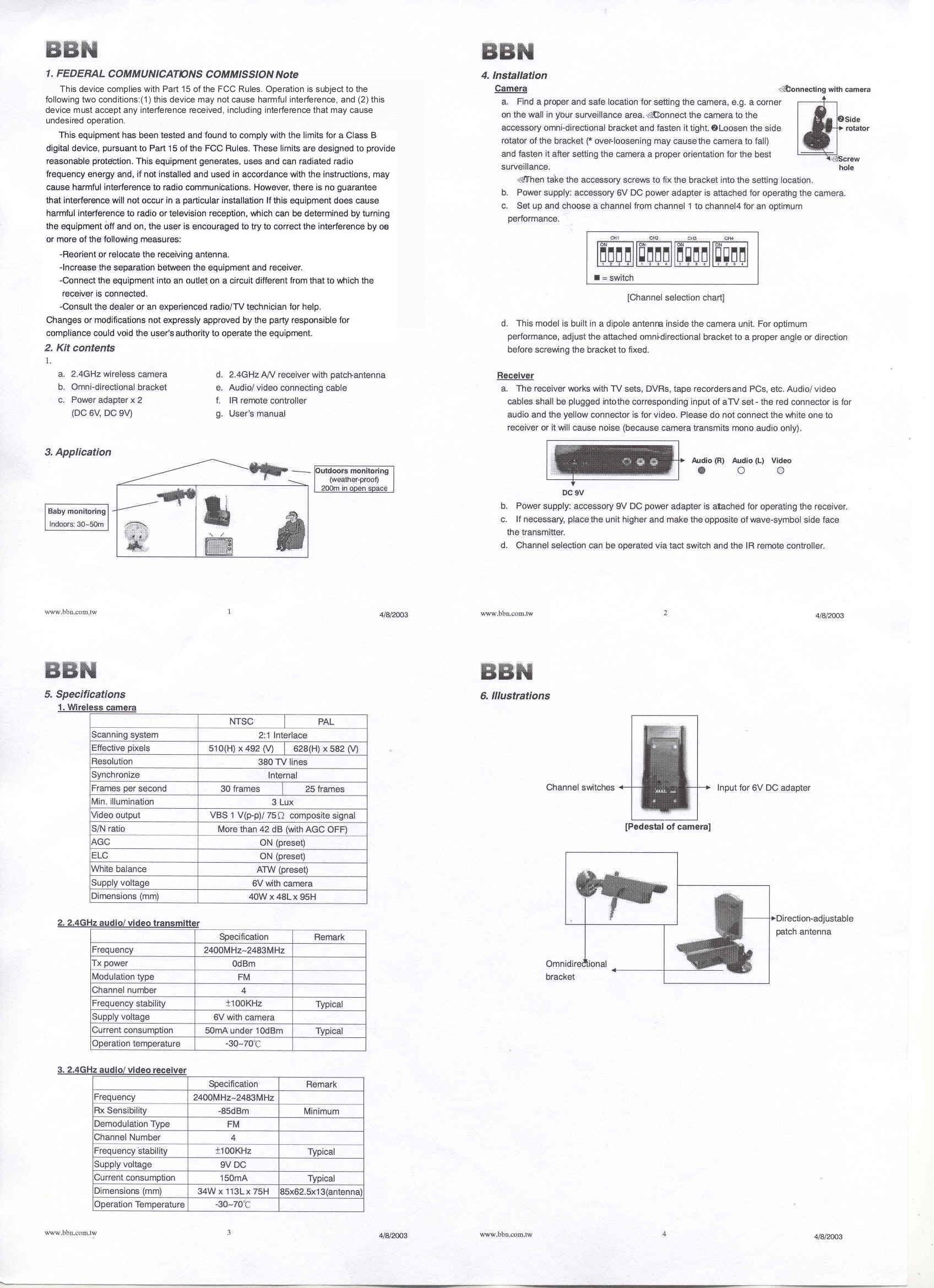
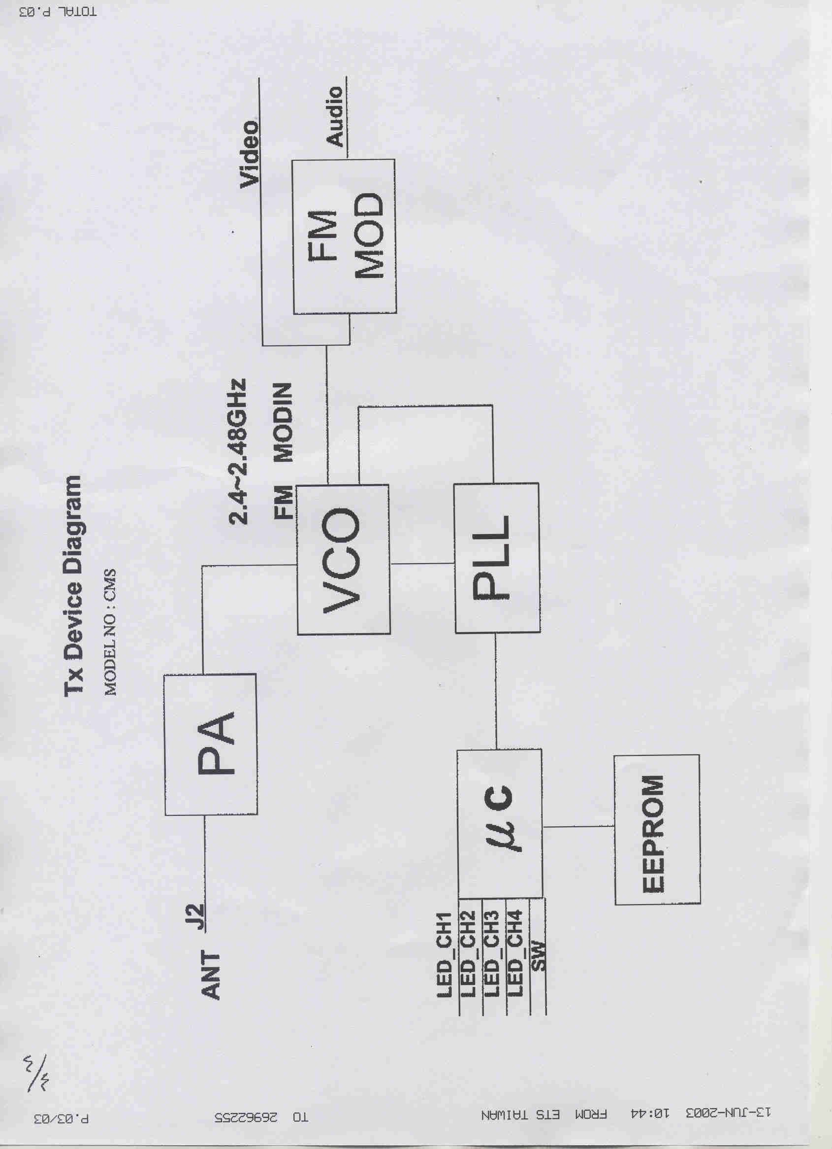
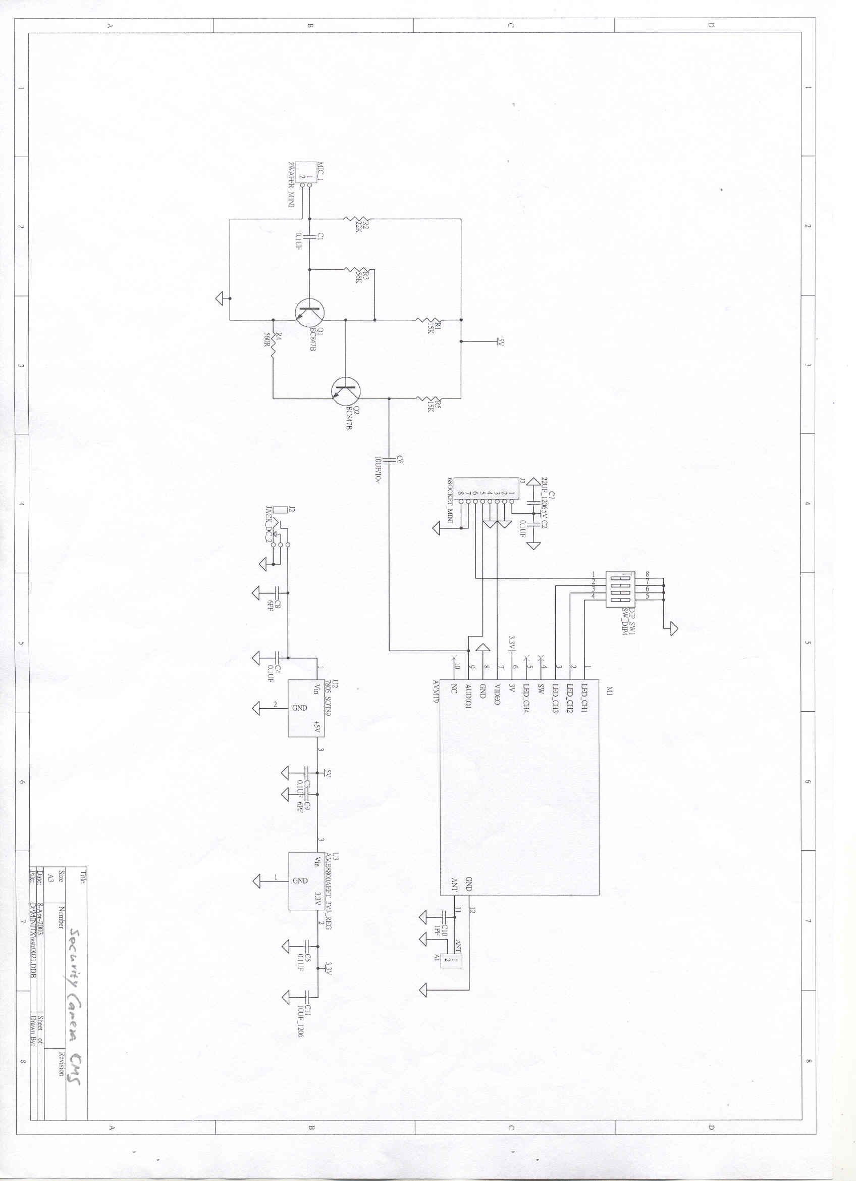
FCC ID: Q77CMS 2.4 GHz Blade Sender Operation Theorem: The product is intended to transmit four channels (2410, 2430, 2450, 2470 MHz) of audio and video signal in modulated 2.4 GHz FM style. Modulation and Transmitting module VMT15 is mainly employed, it consists one video input and two audio inputs according to below circuit diagram. The frequency selection could be set by DIP-SW1, and options shown below: Video input receives 1 Vp-p (PAL or NTSC) signal transmitted from CCD or CMOS cameras. Audio input receives stereo audio signal. The product is energized by a 9 Vdc linear type power supply, converted voltage to 5 Vdc via regulator U1 (7805), than supplies VMT15.
Parts List/Tune Up Info
FEDERAL COMMUNICATIONS COMMISSION Authorization and Evaluation Division 7435 Oakland Mills Road Columbia, MD 21046 U.S.A. To whom it may concern: I, hereby, declare that the following EMI suppression components on the EUT, FCC ID: Q77CMS, will be added or layout on the mass production products. 1. To add copper foil on main board. BEYOND BROADBAND NETWORK, INC. 7F-3, No. 186, Jian Yi Rd., Chung Ho City, Taipei County, Taiwan, R.O.C. Jem Huang / R&D Manager Date: Jun. 20, 2003
Test Report
FCC TEST REPORT Report No. : F332802 SPORTON International Inc. TEL : 886-2-2696-2468 FAX : 886-2-2696-2255 FCC TEST REPORT for 47 CFR, Part 15, Subpart C Equipment : Security Camera Model No. : CMS FCC ID : Q77CMS Filing Type : Certification Applicant : BEYOND BROADBAND NETWORK, INC. 7F-3, No. 186, Jian Yi Rd., Chung Ho City, Taipei County, Taiwan, R.O.C. The test result refers exclusively to the test presented test model / sample. Without written approval of SPORTON International Inc., the test report shall not be reproduced except in full. Certificate or Test Report must not be used by the applicant to claim the product in this test report endorsement by NVLAP or any agency of U.S. government. SPORTON International Inc. 6F, No.106, Sec. 1, Hsin Tai Wu Rd., Hsi Chih, Taipei Hsien, Taiwan, R.O.C. FCC TEST REPORT Report No. : F332802 SPORTON International Inc. FCC ID : Q77CMS TEL : 886-2-2696-2468 Page No. : i FAX : 886-2-2696-2255 Issued Date : May 30, 2003 Table of Contents History of this test report....................................................................................................................................ii CERTIFICATE OF COMPLIANCE........................................................................................................................1 1. General Description of Equipment under Test.............................................................................................2 1.1. Applicant..........................................................................................................................................................................................2 1.2. Manufacturer ...................................................................................................................................................................................2 1.3. Basic Description of Equipment under Test ....................................................................................................................................2 1.4. Feature of Equipment under Test ...................................................................................................................................................2 2. Test Configuration of Equipment under Test ...............................................................................................3 2.1. Test Manner ....................................................................................................................................................................................3 2.2. Description of Test System .............................................................................................................................................................3 2.3. Connection Diagram of Test System ..............................................................................................................................................4 3. Test Software ...................................................................................................................................................5 4. General Information of Test............................................................................................................................6 4.1. Test Facility .....................................................................................................................................................................................6 4.2. Test Voltage ....................................................................................................................................................................................6 4.3. Standard for Methods of Measurement...........................................................................................................................................6 4.4. Test in Compliance with ..................................................................................................................................................................6 4.5. Frequency Range Investigated .......................................................................................................................................................6 4.6. Test Distance ..................................................................................................................................................................................6 5. Test of Conducted Powerline .........................................................................................................................7 5.1. Major Measuring Instruments..........................................................................................................................................................7 5.2. Test Procedures ..............................................................................................................................................................................8 5.3. Typical Test Setup Layout of Conducted Powerline .......................................................................................................................9 5.4. Test Result of AC Powerline Conducted Emission .......................................................................................................................10 6. Test of Radiated Emission............................................................................................................................16 6.1. Major Measuring Instruments........................................................................................................................................................16 6.2. Test Procedures ............................................................................................................................................................................17 6.3. Typical Test Setup Layout of Radiated Emission............................................................................................................…
Text truncated - open the document above for the full version.
Test Setup Photos
FCC TEST REPORT Report No. : F332802 SPORTON International Inc. FCC ID : Q77CMS TEL : 886-2-2696-2468 Page No. : 1 of 3 FAX : 886-2-2696-2255 Issued Date : May 30, 2003 1.1. Photographs of Conducted Emission Test Configuration The photographs show the configuration that generates the maximum emission. FRONT VIEW REAR VIEW FCC TEST REPORT Report No. : F332802 SPORTON International Inc. FCC ID : Q77CMS TEL : 886-2-2696-2468 Page No. : 2 of 3 FAX : 886-2-2696-2255 Issued Date : May 30, 2003 SIDE VIEW FCC TEST REPORT Report No. : F332802 SPORTON International Inc. FCC ID : Q77CMS TEL : 886-2-2696-2468 Page No. : 3 of 3 FAX : 886-2-2696-2255 Issued Date : May 30, 2003 1.2. Photographs of Radiated Emission Test Configuration The photographs show the configuration that generates the maximum emission. FRONT VIEW REAR VIEW
Contact Information
Applicant
Jem Huang(Manager)
Test Firm
Sporton International Inc.Kathy Lin
Technical Specifications
| # | Rule Parts | Frequency Range | Power Output |
|---|---|---|---|
| 1 | 15C | 2.41 GHz - 2.47 GHz | - |
Other Applications from Beyond Broadband Network, Inc.
Q77TXRC37
Feb 01, 2004Remote Control Transmitter
Equipment Class
DSC - Part 15 Security/Remote Control Transmitter
Q77VSB
Jul 22, 2003BLADE SENDER
Equipment Class
DXX - Part 15 Low Power Communication Device Transmitter