Q77TXRC37Remote Control Transmitter
Beyond Broadband Network, Inc.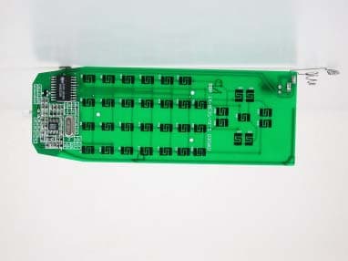
Click to zoom
Application Details
- Equipment Class
- DSC - Part 15 Security/Remote Control Transmitter
- Date of Grant
- Feb 01, 2004
- Application Purpose
- Original Equipment
- Date of Application
- Feb 01, 2004
- Equipment Note
- Remote Control Transmitter
- Frequency Range
- 433.92000000 - 433.92000000
- Country
- Taiwan
Documents & Files
Document Text
Text extracted from the exhibit documents filed with the FCC. Open a document above to read the original.
Users Manual
2 2 . . 4 4 G G H H z z W W i i r r e e l l e e s s s s T T V V B B o o x x User Manual 1 1. Packaging 1.1 Transmitter × 1 and Receiver × 1 1.2 2.4GHz Omni-directional Antenna × 1 1.3 Remote Controller × 1 (Supplied with two AAA Batteries) 1.4 Two-way RF Splitter × 1 1.5 DC9V Adaptor × 2 (for Transmitter and Receiver) 1.6 CATV Cable (1M) × 1 1.7 RCA A/V Cable (1.5M) × 1 1.8 Screw Mount × 3 1.9 User Manual × 1 2. Features 2.1 Watch cable TV on additional CRT or LCD monitor in separate rooms via 2.4GHz wireless transmission. Note: Monitor should be equipped with RCA input. 2.2 Transmits CATV signals via the Transmitter or signals from other video equipment such as VCR, DVD, VCD, satellite receiver, and video camera by wireless. 2.3 Transmitting range is about 30~40 meters indoors (estimated). 2.4 Built-in 433MHz and IR remote give commands over the transmitter and the receiver separately. 2.5 Encoded 433MHz remote avoids interference caused by other 433MHz products. 2.6 Memory function enables the devices to remain on last used channel. 2 3. Specifications 3.1 Transmitter Frequency 2400~2483MHz Transmitting Power 0dBm(FCC)/10dBm(CE) No. of Channels 4 (2410, 2430, 2450, 2470) Video In/Out Cable, Air TV, Composite Video System NTSC/PAL/SECAM Remote Control 433MHz Power Consumption DC9V, 500mA Operating Temperature -10 ~ 50 Weight 260g Dimensions (W×H×D) 152 × 125 × 35 (mm) 3.2 Receiver Frequency 2400~2483MHz No. of Channels 4 (2410, 2430, 2450, 2470) Video Out Composite Remote Control Infrared Video Output Level 1 Vp-p Power Consumption DC9V, 500mA Operating Temperature -10 ~ 50 Weight 140g Dimensions (W×H×D) 117 × 85 × 42 (mm) 3.3 Approvals FCC/CE 3 VCR/VCD/DVD in 4. Installation 4.1 Transmitter Please note that this device is mainly for home use. It is better not to place it under sunlight. Please keep it away from heat, humid, dusty, or greasy environment. 4.1.1 Find the CATV signal source. Generally, it is fixed on walls of the house or under roof. 4.1.2 Get CATV cable. If there is only one TV, just connect the CATV signal source with the transmitter. Otherwise, connect it with the attached 2-way RF splitter input. Then connect one splitter output with the transmitter and the other splitter output with the TV via CATV cable. 4.1.3 Connect a VCR/VCD/DVD player with the transmitter via RCA A/V cable. Make sure that the colors (yellow, white, and red) match. You may CATV cable in LED light shows channel of 2.4GHz transmission Diagram 2: Diagram 1: A/V cable SMA connector (connected with the attached 2.4GHz antenna) DC9V A/V in RF connector (connected with CATV cable) LED light shows channel of 2.4GHz transmission 4 press “INPUT” or use the remote (see instructions in Section 5: Remote Controller) to switch mode (TV or A/V). 4.1.4 Power the transmitter with the attached DC9V adaptor. Please make sure that the DC jack is plugged in before power on. 4.1.5 Press “P/W” or use the remote. Check if the transmitter is turned on. The LED light shall light up after power on. 4.1.5 Press “CH” or use the remote to select a channel of transmission. Later in setting up the receiver, make sure the channel shall be same as the transmitter. 4.1.6 In order to get the best transmission quality, place the transmitter in a favorable place. Adjust antenna direction till the picture gets clear and steady. Generally, make the antenna stand straight. 4.2 Receiver Please note that this device is mainly for home use. It is better not to place it under sunlight. Please keep it away from heat, humid, dusty, or greasy environment. 4.2.1 Turn on the TV and then switch to A/V mode. 4.2.2 Connect the receiver with the TV A/V Input via RCA A/V cable. Please make sure that the colors (yellow, white, and red) match. 4.2.3 Power the receiver with the attached DC9V adaptor. Please make sure Tact switch for 2.4GHz receiving channels DC9V Adaptor Display shows channel of transmission A/V cable connects the receiver with the TV (A/V in) Directional antenna (front) House Monitoring Baby Monitoring Wireless Camera (option) Wireless Camera (Option) Wireless TV Transmitter 5 Options to buy: Wireless Camera (regular, covert, and etc.) When there are multiple transmitters working at your place, just use the remote to switch receiving channels. No need to move and may be able to see pictures sent from other transmitters such as wireless camera. Please refer to the local distributors for optional wireless products. that the DC jack is plugged in before power on. 4.2.4 Make sure that the digit-display (red light) lights up after power on. 4.2.5 Switch channel of transmission via tact switch or remote (see instructions in Section 5: Remote Controller) to same as the transmitter. 4.2.6 The receiver shall start to receive pictures from the transmitter now. Please adjust antenna direction till the picture gets clear and steady. Generally, it is better to make the antenna (front) face the transmitter. 5. Remote Controller 5.1 Using the Remote Controller *FUNC: Please refer to Section 6.3 for further details. Power Power On/Off the transmitter TX. CH Switch 2.4GHz transmitting channels of Tx RX. CH Switch 2.4GHz receiving channels of Rx TV/AV Switches TV and Video input on transmitter FUNC* Sets up an new encoded address of the remote SCAN Automatically scans all TV channels CH + − Adds or deletes TV channels CH+/CH- Switches TV channels in sequence VOL+/VOL- Turns up or down the output volume MUTE Silent DISPALY Shows OSD status JUMP Turns back to the previous TV channel MTS Bilingual system 0~9 Selects a TV channel directly by pressing number keys 6 5.2 Installing the Batteries The remote uses 2 AAA alkaline batteries for power. We recommend using high-quality batteries. 5.2.1 Remove the battery compartment door by pressing the tab allowing to door to be removed. 5.2.2 Install 2 AAA alkaline batteries (included) into the battery compartment. Be certain to follow the + and − symbols in the compartment. Installing the batteries incorrectly will …
Text truncated - open the document above for the full version.
Cover Letter(s)
1 Chris Harvey From:[email protected] Sent:Monday, January 12, 2004 12:55 AM To:Chris Harvey Subject:Re: FCC Label Location needed for Beyond Broadband FCCID: Q77TXRC37 AN03T3543 ID Label.pdf (1 MB) Hi Chris, Attached please find photograph of the location of the FCC ID label for your reference, thanks! Best regards, Rick Hu ----- Original Message ----- From: "Chris Harvey" <[email protected]> To: <[email protected]> Cc: "Chris Harvey" <[email protected]> Sent: Monday, January 12, 2004 10:57 AM Subject: FW: FCC Label Location needed for Beyond Broadband FCCID: Q77TXRC37 AN03T3543 > Rick, > > Review of the application revealed that there was no Label Location Diagram > submitted as required by the FCC Rules. Please submit a photograph or > drawing showing the location of the FCC ID label. > > The items indicated above must be submitted before processing can > continue on the above referenced application. Failure to provide the > requested information within 30 days of the original e-mail date may > result in application dismissal and forfeiture of the filing fee. > Also, please note that partial responses increase processing time and > should not be submitted. > Any questions about the content of this correspondence should be > directed to > the e-mail address listed below the name of the sender. > > Please send the exhibit to [email protected] > > Best regards, > > Chris Harvey
External Photos
ETC Report No.: ET92S-10-058-02Page A1 of A1 FCC ID: Q77TXRC37 ANNEX A: CONSTRUCTION PHOTOS OF EUT 1. Front view of EUT 2. Rear view of EUT
Internal Photos
ETC Report No.: ET92S-10-058-02Page B1 of B2 FCC ID: Q77TXRC37 ANNEX B:CONSTRUCTION PHOTOS OF EUT 1. Inside 1 of EUT 2. Inside 2 of EUT ETC Report No.: ET92S-10-058-02Page B2 of B2 FCC ID: Q77TXRC37 3. Front view of PCB 4. Rear view of PCB
Test Report
FCC ID: Q77TXRC37 Rev. No 1.0 FCC Part 15 Subpart C TEST REPORT of E.U.T. : 433.92MHz Remote Control FCC ID. : Q77TXRC37 MODEL : TXRC37 Working Frequency: 433.92MHz for APPLICANT : BEYOND BROADBAND NETWORKS, INC. ADDRESS: 7F-3, No.186, Jian Yi Rd., Chung Ho City. Taipei County, Taiwan, R.O. C. Test Performed by ELECTRONICS TESTING CENTER, TAIWAN NO. 8, LANE 29, WEN-MING RD., LO-SHAN TSUN, KUI-SHAN HSIANG, TAOYUAN HSIEN 333, TAIWAN, R.O.C. Tel: (03)3276170-3276174 Fax: (03)3276188 Report Number: ET92S-10-058-02 ETC Report No.: ET92S-10-058-02FCC ID: Q77TXRC37 Rev. No 1.0 TEST REPORT CERTIFICATION Applicant: BEYOND BROADBAND NETWORKS, INC. 7F-3, No.186, Jian Yi Rd., Chung Ho City. Taipei County, Taiwan, R.O. C. Manufacturer: UNIVERSAL MICROELECTRONICS CO.,LTD. 3, 27 TH RD., TAICHUNG INDUSTRIAL PARK. TAICHUNG , TAIWAN. R.O.C. Description of EUT: a) Type of EUT: 433.92MHz Remote Control b) Trade Name: BBN c) Model No.: TXRC37 d) FCC ID: Q77TXRC37 e) Working Frequency : 433.92MHz f) Power Supply: 3VDC Regulation Applied: FCC Rules and Regulations Part 15 Subpart C (2003) I HEREBY CERTIFY THAT; The data shown in this report were made in accordance with the procedures given in ANSI C63.4 and the energy emitted by the device was founded to be within the limits applicable. I assume full responsibility for accuracy and completeness of these data. Note: 1. The results of the testing report relate only to the items tested. 2. The testing report shall not be reproduced except in full, without the written approval of ETC. Test Date: Dec. 03, 2003 Test Engineer: Approve & Authorized Signer: Win-Po Tsai, Supervisor, NVLAP Signatory EMC Dept. I of ELECTRONICS TESTING CENTER, TAIWAN ETC Report No.: ET92S-10-058-02FCC ID: Q77TXRC37 Rev. No 1.0 Table of Contents Page 1. GENERAL INFORMATION ...................................................................................................................................... 1 1.1 P RODUCT D ESCRIPTION ................................................................................................................................................. 1 1.2 C HARACTERISTICS OF D EVICE : ...................................................................................................................................... 1 1.3 T EST M ETHODOLOGY .................................................................................................................................................... 1 1.4 T EST F ACILITY ............................................................................................................................................................... 1 2. DEFINITION AND LIMITS ....................................................................................................................................... 2 2.1 D EFINITION .................................................................................................................................................................... 2 2.2 R ESTRICTED B ANDS OF O PERATION .............................................................................................................................. 2 2.3 L IMITATION ................................................................................................................................................................... 2 2.4 L ABELING R EQUIREMENT .............................................................................................................................................. 4 2.5 U SER I NFORMATION ...................................................................................................................................................... 4 3. RADIATED EMISSION MEASUREMENT ............................................................................................................. 5 3.1 A PPLICABLE S TANDARD ................................................................................................................................................ 5 3.2 M EASUREMENT P ROCEDURE .......................................................................................................................................... 5 3.3 T EST D ATA .................................................................................................................................................................... 7 3.4 F IELD S TRENGTH C ALCULATION ................................................................................................................................. 13 3.5 R ADIATED T EST E QUIPMENT ....................................................................................................................................... 13 3.6 M EASURING I NSTRUMENT S ETUP ................................................................................................................................19 3.7 R ADIATED M EASUREMENT P HOTOS ............................................................................................................................. 20 4. BANDWIDTH OF EMISSION.................................................................................................................................. 22 4.1 A PPLICABLE S TANDARD P LOT G RAPHIC OF B ANDWIDTH ............................................................................................ 22 4.2 B ANDWIDTH T EST E QUIPMENT .................................................................................................................................... 22 4.3 T EST R ESULT ............................................................................................................................................................... 22 5. CONDUCTED EMISSION MEASUREMENT ........................................................................................................ 25 6. LIMIT OF TRANSMISSION TIME ......................................................................................................................... 26 6.1 A PPLICABLE S TANDARD ..…
Text truncated - open the document above for the full version.
Test Setup Photos
ETC Report No.:ET92S-10-058-02Sheet 1 of 2 Sheets FCC ID: Q77TXRC37 3.7 Radiated Measurement Photos X axial Y axial ETC Report No.:ET92S-10-058-02Sheet 2 of 2 Sheets FCC ID: Q77TXRC37 Z axial
Contact Information
Applicant
Jem Huang(Manager)
Test Firm
Electronics Testing Center, TaiwanWin-Po Tsai
Technical Specifications
| # | Rule Parts | Frequency Range | Power Output |
|---|---|---|---|
| 1 | 15.231 | 433.92 MHz - 433.92 MHz | - |
Other Applications from Beyond Broadband Network, Inc.
Q77CMS
Jul 22, 2003SECURITY CAMERA
Equipment Class
DXX - Part 15 Low Power Communication Device Transmitter
Q77VSB
Jul 22, 2003BLADE SENDER
Equipment Class
DXX - Part 15 Low Power Communication Device Transmitter