Q78-A12GSM Dual Band Digital Mobile Phone
ZTE Corporation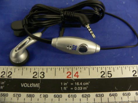
Click to zoom
Application Details
- Equipment Class
- PCE - PCS Licensed Transmitter held to ear
- Date of Grant
- Jul 06, 2005
- Application Purpose
- Original Equipment
- Date of Application
- Jul 06, 2005
- Equipment Note
- GSM Dual Band Digital Mobile Phone
- Frequency Range
- 824.00000000 - 849.00000000
- Company
- ZTE Corporation
- Country
- China
Documents & Files
Document Text
Text extracted from the exhibit documents filed with the FCC. Open a document above to read the original.
Users Manual
1 A12 GSM Dual-band Digital Mobile Phone User Manual 2 Copyright © 200 5 by ZTE Corporation All rights reserved. No part of this publication may be excerpted, reproduced, translated or utilized in any form or by any means, electronic or me chanical, including photocopying and microfilm, without the prior written permission of ZTE Corporation. The manual is published by ZTE Corporation. We reserve the right to make modifications on print errors or update specific ations without prior notice. Edition: 1 st edition, March, 2005 3 Contents 1 GENERAL INFORMATION........................................................1 1.1 W ELCOME ................................................................................1 1.2 S ECURITY .................................................................................1 1.3 S AFETY P RECAUTIONS ..............................................................2 2 GETTING STARTED..................................................................10 2.1 K EY D EFINITION .....................................................................10 2.2 D ISPLAY S YMBOLS .................................................................12 2.3 T ECHNICAL P ARAMETERS .......................................................13 2.4 B ATTERY .................................................................................14 2.4.1 Removing & Installing the Battery.................................14 2.4.2 Charging the Battery......................................................15 2.5 C ONNECTING TO THE N ETWORK .............................................17 4 2.5.1 SIM Card ....................................................................... 17 2.5.2 Inserting & Removing SIM Card................................... 18 2.5.3 Power on/off Your Phone............................................... 18 2.5.4 Unlocking the SIM Card and Mobile Phone ................. 19 2.5.5 Connecting to the Network ............................................ 20 3 BASIC OPERATIONS ............................................................... 21 3.1 M AKING A C ALL .................................................................... 21 3.2 A NSWERING A C ALL .............................................................. 24 3.3 C ALL M ENU ........................................................................... 24 4 FUNCTION MENU .................................................................... 26 4.1 U SAGE AND S TRUCTURE OF F UNCTION M ENU ...................... 26 4.2 S HORT M ESSAGE ................................................................... 27 4.3 P HONE M ENUS ....................................................................... 31 4.3.1 Call Logs ....................................................................... 32 5 4.3.2 Diverts............................................................................33 4.3.3 Firewall ..........................................................................35 4.4 P ROFILES ................................................................................37 4.5 S ETTINGS ................................................................................39 4.5.1 Phone Settings................................................................39 4.5.2 Display Settings .............................................................40 4.5.3 Clock Settings.................................................................40 4.5.4 Call Settings ...................................................................41 4.5.5 Network Settings ............................................................42 4.5.6 Security Settings .............................................................42 4.5.7 Factory Settings .............................................................45 4.6 T OOLKIT .................................................................................45 4.6.1 Alarm Clock ...................................................................46 4.6.2 Calculator ......................................................................47 4.6.3 Stopwatch .......................................................................48 4.6.4 World Clock....................................................................48 6 4.7 G AMES ................................................................................... 48 4.8 N AMES ................................................................................... 49 4.8.1 Searching....................................................................... 51 4.8.2 Editing ........................................................................... 52 4.8.3 Deleting ......................................................................... 52 4.8.4 Making an IP Call ......................................................... 52 4.8.5 Adding New Name......................................................... 52 4.8.6 Settings .......................................................................... 53 4.8.7 Batch Operation ............................................................ 53 5 TEXT INPUT .............................................................................. 55 5.1 O VERVIEW ............................................................................. 55 5.2 K EYBOARD D EFINITION ......................................................... 55 5.3 C HARACTER C HART ............................................................... 56 6 TROUBLESHOOTING ............................................................. 59 1 1 General Information 1.1 Welcome Thank you for using A12 GSM digital mobile phone. To guarantee the mobile phone always in its best condition, please read this manual carefully and keep it for further use. The pictures, symbols and contents in this ma nual are just for your reference. They might not be completely identical with your cellular phone. Please subject to the material object. ZTE operates a policy of continuous dev elopment. We reserve the right to update the technical specifications in …
Text truncated - open the document above for the full version.
Block Diagram
A12 HANDSET BLOCK DIAGRAM AUDIO SECTION LCD SYSTEM CONNECTOR KEYBORD MEMORY AD6525 SIM CARD AD6537 RF SECTION BATTERY ANTENNA A12 MAINBOARD A12 Handset Operating Frequency Range MobileTX(MHz) MobileRX(MHz) GSM850 824-849 869-894 EGSM900 880-915 925-960 DCS 1710-1785 1805-1880 PCS 1850-1910 1930-1990
Cover Letter(s)
Federal Communications Commission Authorization and Evaluation Division Confidentiality Request regarding application for certification of FCC ID: Q78-A12. Pursuant to Sections 0.457 and 0.459 of the Commission’s Rules, we hereby request confidential treatment of information accompanying this application as outlined below: (1? PCB layout (2? BOM list (3? Schematic diagram The above materials contain trade secrets and proprietary information not customarily released to the public. The public disclosure of these materials may be harmful to the applicant and provide unjustified benefits to its competitors. The applicant understands that pursuant to Section 0.457 of the Rules, disclosure of this application and all accompanying documentation will not be made before the date of the Grant for this application. Sincerely Yours, Signature: Typed or Printed Name: Royce Wang Title: Product Certification Director Company Name: ZTE Corporation
External Photos
EXHIBIT C - EUT PHOTOGRAPHS EUT Front View EUT Rear View EUT Port View Adapter Earphone
ID Label/Location Info
EXHIBIT A - FCC ID LABELING AND WARNING STATEMENT Proposed FCC ID Label Specifications: Text is black or white in color and is left justified. Labels are silk-screened and shall be “permanently affixed” at a conspicuous location on the EUT. Proposed Label Location on EUT EUT Battery Cover off View of the EUT/ID Label Location FCC Warning Statement A FCC Warning Statement is provided in the product manual. FCC ID: Q78-A12
Internal Photos
EUT Battery Cover Off View EUT Cover Off View EUT Component with Shielding View EUT Component without Shielding View EUT Displayer and Keyboard View Battery
Operational Description
Technical Specifications and Descriptions of A12 GSM Handset Technical Specifications and Description Of GSM Mobile Handset Model--A12 Version 1.0 9, Jun. 2005 ZTE CORPORATION All rights are reserved. Reproduction in whole or in parts is prohibited without the written consent of the copyright owner www.zte.com.cn Page 1 of 12 Technical Specifications and Descriptions of A12 GSM Handset 1 Abstract This document gives brief technical specification & description of our product—A12 2 Abbreviations AMR Adaptive Multi Rate BB Base Band BAI Baseband Audio Interface DAI Digital-Audio-Interface DTMF Dual Tone Multi Frequency function EFR Enhanced Full Rate FDN Fixed dialing number FEM Front End Module FR Full Rate GSM Global system for mobile communications IC Integrated circuit JTAG IEEE standardized test interface for IC’s LCD Liquid Crystal Display LNA Low noise amplifiers PA Power amplifier PCB Printed Circuit Board PCS Public cellular system PMU Power Management Unit RF Radio Frequency RX Receiver SIM Subscriber Identity Module All rights are reserved. Reproduction in whole or in parts is prohibited without the written consent of the copyright owner www.zte.com.cn Page 2 of 12 Technical Specifications and Descriptions of A12 GSM Handset TC Transceiver TX Transmitter USB Universal Serial Bus VCO Voltage controlled oscillator VTCXO Voltage controlled temperature compensated x-tal oscillator 3 Product Features 3.1 General specification Item Feature Remarks Protocol GSM 850/1900 MHz Dual-band Standard GSM Phase 2+ With SIM Size 106mm x 44.4mm x 16.8mm With battery Weight 77g With battery Talk / Standby Time 2 – 4h / 60 – 130h Operating Temp. Standard-15 +35 Limit-10 +55 Antenna Internal 50Ω 1/4λ Form Factor Bar type Memory Flash 32Mbit SRAM4Mbit LCD Main96 x 64 dots Amber, white or blue back light Keyboard lights Amber or blue All rights are reserved. Reproduction in whole or in parts is prohibited without the written consent of the copyright owner www.zte.com.cn Page 3 of 12 Technical Specifications and Descriptions of A12 GSM Handset Battery Standard Battery Li-ion,710mAh Phone book 300 names WAP No MMS No GPRS No Melody Yes 16 Midi Vibrator Yes Side Volume Key No 3.2 Hardware specification Item Feature Remarks Chipset MakerANALOG DEVICES BB Chipset AD6525XCA , AD6537B RF Chipset AD6539, RF3146 PCB Main Board8-layers, 1.1mm Talk time Up to 240 minutes Estimated Standby time Up to 130 hrs Estimated Charging time 2.0hrs @ Std battery Frequency Range TX 824-849MHz ;1850-1910MHz; RX All rights are reserved. Reproduction in whole or in parts is prohibited without the written consent of the copyright owner www.zte.com.cn Page 4 of 12 Technical Specifications and Descriptions of A12 GSM Handset 869 -894MHz ;1930-1990MHz; Band Width 0.2MHz Vocoder FR, EFR,HR AMR optional Modulation/ Demodulation GMSK Chip Rate MCU 39MHz, DSP 65MIPS RX sensitivity -102 dBm (GSM850/PCS) Conducted emission Conducted Static conditions TX output power Maximum 33dBm(+/-2dB) (GSM850) 30dBm(+/-2dB) (PCS) Minima 5dBm(+/-5dB) (GSM850) 0dBm(+/-5dB) (PCS) Normal test conditions SIM card Plug-In Type, 3V Pre-paid SIM Yes Status Indicator 2 Color LED System connector 18 Pin Ear Phone Jack ZTE Special I/F Speaker 8Ω Ear-microphone Yes Optional Battery Charger No Travel Adapter Yes All rights are reserved. Reproduction in whole or in parts is prohibited without the written consent of the copyright owner www.zte.com.cn Page 5 of 12 Technical Specifications and Descriptions of A12 GSM Handset 3.3 Software specification Item Feature Remarks Mandatory Display of Called Number Support Mandatory Indication of Call Progress Signals Support Mandatory Country/PLMN Indication Support Mandatory Country/PLMN Selection Support, Mandatory Keypad Support Mandatory IMEI Support Mandatory Short Message Support Mandatory Short Message Overflow Indication Support Optional International Access Function ("+" key) Support Mandatory Service Indicator Support Mandatory Emergency Calls capabilities Support Mandatory Dual Tone Multi Frequency function (DTMF) Support Mandatory Subscription Identity Management Support Mandatory On/Off switch Support optional Sub-address Support Mandatory Support of Encryption A5/1 and A5/2 Support optional Short Message Service Cell Broadcast DRX Support optional Service Provider Indication Support GSM 02.07 Functions Mandatory Ciphering Indicator Support Other Sending or receiving SMS All rights are reserved. Reproduction in whole or in parts is prohibited without the written consent of the copyright owner www.zte.com.cn Page 6 of 12 Technical Specifications and Descriptions of A12 GSM Handset SMS group sending Fixed dialing number (FDN)if SIM card supporting pin2 service Earphone answer through earphone button Out-going calls restriction Out-going added service (out-going call waiting, out-going, call holding, multi-parties meeting, etc.). network support is required Store the last 10 answered calls, last 10 missed calls and 20 dialing calls ( show the date, time, number, name and duration ) PIN error alert when opening large capacity of directory On/Off timing Earphone, speaker, ring volume adjustable by multilevel battery meter and the signal intensity indicator Call metering Alarm Calculator Games Directory groups Conventional phone book that have three hundred name card Call time limit: when approaching n seconds, a alert will be displayed Show in-coming call Functions Vibration All rights are reserved. Reproduction in whole or in parts is prohibited without the written consent of the copyright owner www.zte.com.cn Page 7 of 12 Technical Specifications and Descriptions of A12 GSM Handset Situation modes selection. User select different ring patterns according different situations Animation menu icon Out-going call restriction. user can define the in- call and out-call list In-coming call mute. User can turn off the ring 4 Solution of the Product The A12 handset hardware uses Analog Devices (ADI) 430 family chipset, which …
Text truncated - open the document above for the full version.
Parts List/Tune Up Info
Tuning Up Procedure & Operational Manual 1 of 24 ZTE Proprietary & Confidential Tuning Up Procedure & Operational Manual Model: A12 Version 1.0 9, Jun. 2004 ZTE CORPORATION Tuning Up Procedure & Operational Manual 2 of 24 ZTE Proprietary & Confidential 5.1 General description 5.1.1 Product overview: A12 product is new model phone designed by ZTE, it works at four band, EGSM?GS M?DCS and PCS band. Its weight is only 77g, the size is 106mm × 44.4mm × 16.8mm.. I t has STN screen which pixels is 96 x 64 dots and has 16 polyphonies. A12 CPU runs a 13MHz, with 32M Flash Memory and 4M SRAM. The main IC includ e baseband chip (AD6537B and AD6525XCA), RF chip (AD6539?RF3146) and memory chip. A12 can dial 3 hours continuously and can be in idle mode up to 130 hours, using 710mAH battery. Tuning Up Procedure & Operational Manual 3 of 24 ZTE Proprietary & Confidential 3.1 Principle of Rx Circuit 3.1.1 A12 supports quad bands: GSM 850/EGSM 900/DCS 1800/PCS 1900. GSM 850: PCS: Channel Range :128-251 Channel Range :512-810 Downlink:869MHZ-894MHZ Downlink:1930MHZ-1990MHZ Uplink: 824MHZ-849MHZ Uplink:1850MHZ-1910MHZ Duplexer:45 MHZ Duplexer:80 MHZ Bandwidth:200 KHZ Bandwidth:200 KHZ Power Level Range:5-19 Power Level Range:0-15 3.1.2 A12 Block Diagram for Receive Path: 3.1.3 Signal is coming from the RF Connector. RF Connector is designed for testing; with the RF cable and equipment our test engineers can analyze the Rx/Tx signal through the RF Connector. The Signal goes into RF_Switch from the RF Connector to control the working status. After the signal comes out from RF_Switch, it goes into the related Saw Filter, and the signal turns into two signals. Tuning Up Procedure & Operational Manual 4 of 24 ZTE Proprietary & Confidential U1000 is the transceiver, a very important chip set. For the receive part, it mainly completes: LNAs(Low Noise Amplifiers)?Down-Converting Mixers ?Baseband Amplifiers / Low Pass Filters and so on. Four differential LNAs with programmable-gain drive a direct conversion demodulator that mixes down the received signal to baseband. The down converted signals then pass in quadrature to the baseband programmable-gain amplifiers and low pass filters for channel selection. The programmable-gain baseband amplifiers and the LNA gains are set via a standard 3-wire serial bus. The baseband signals inside the Baseband Processor will be proceeded with analog to digital conversion?decoding?digital processor?digital to analog conversion, and the audio signal will be available to drive receiver. 3.1.4 Receive path circuit tuning up We separate the failures in 3 parts: Logic failure, receiver failure and transmission failure. First we need define the failure according to the failed item then we begin the analysis in detail. Receiver key parameters include: RX LEVEL?RX QUALITY?MOBILE CALL? Tuning Up Procedure & Operational Manual 5 of 24 ZTE Proprietary & Confidential FLATNESS?TIME MASK?PHASE ERROR?FREQUENCY ERROR, etc. Here are the equipment we need to analyzer the problems(Such as. EGSM): a. Set Agilent8960 to the specific channel and altitude of transmitter of the basestation . b. Power on the mobile,the mobile is connected with Agilent8960 by the RF cable, and let the mobile be in the receive & testing mode. c. Power meter and oscilloscope. Step1:Measure the received signal according to signal flowing chart. Measure the signal with spectrum analyzer on L1401 to check if the input signal is right. If wrong signal was detected it maybe J1400 cold sold or part defect. Measure the signal on pin2 of U1300 to check if the input signal is right. If wrong signal was detected it maybe C1401 cold soldering, tombstone part, part missing or screwed part. Step2: Measure the output signal from U1300 to check if the signal is right, GSM850 signal: measured from pin 10 (Measure at C1311); EGSM signal: measured from pin 11 (Measure at L1321); DCS signal: measured from pin12 (Measure at L1331), and for PCS from pin 13 at (Measure at R1341). If the signal is not right, should check if U1300 cold soldering, soldering short part, part defect or un-soldering. If no defect was found at U1300, then check if the control signal “TR_SW1_RF, TR_SW2_RF, TR_SW3_RF, TR_SW4_RF” is right. If the signal is not right please check D101 and parts around them. If no clear issue found, change U1300,D101, one by one. Step3: Measure the input signal and output signal of SAW Filter. If the input signal is wrong, check on C1311:GSM850,L1321: EGSM ,L1331: DCS and R1341:PCS. If the output signal is wrong , check the filter U1210:GSM850, U1220:EGSM,U1230:DCS, U1240:PCS. Step4: Measure I/Q signal output from U1000. If the signal is not good, check if there Tuning Up Procedure & Operational Manual 6 of 24 ZTE Proprietary & Confidential are defects on U1000. Also need check the working voltage of U1000. 3.2.1 Transmit path circuit block diagram 3.2.2 Audio signal turns into electrical signal by MIC,changes into baseband signals by A\D conversion?encoding?D\A conversion into U1000. The transmit section of U1000 radio consists of a quadrature modulator, a high speed phase-frequency detector (PFD), with charge pump output, a Tx VCO and a feedback down converting mixer. These components implement a translation loop modulator for directly modulating baseband signals. The VCO output (divided by 2 for low band) is fed to the power amplifier (a portion of the transmitted signal is also fed back into the down-converting feedback mixer as part of the translation modulator feedback loop). An integrated power control loop is used to control the power amplifier’s output level. RF signal comes out of RF-PA(U1100) and transmits from the antenna by the RF-Connector. 3.2.3 Transmit circuit tuning up Key parameter of Tx circuit is “Freq. error”, “MAX POWER”, “TX-CURRENT”, “PA table”, etc. Following is normal analysis of the circuit, according to failed item to do more analysis. Confirm the instrument for analysis is good: a. Power on the mobile,enter the k…
Text truncated - open the document above for the full version.
Parts List/Tune Up Info
Tuning Up Procedure & Operational Manual 13 of 24 ZTE Proprietary & Confidential Tuning Up Procedure & Operational Manual 14 of 24 ZTE Proprietary & Confidential Pins Description of AD6525: Tuning Up Procedure & Operational Manual 15 of 24 ZTE Proprietary & Confidential Tuning Up Procedure & Operational Manual 16 of 24 ZTE Proprietary & Confidential Tuning Up Procedure & Operational Manual 17 of 24 ZTE Proprietary & Confidential D501: Memory chip adopts K5A3240YTCT755. It integrates with 32M Bit Fla sh Memory and 4M Bit SRAM. BLOCK DIAGRAM Tuning Up Procedure & Operational Manual 18 of 24 ZTE Proprietary & Confidential Pins description is as below: 3.3.2 Logic circuit tuning up: Cannot power on a. Turn on power supply, test the pin-VBAT of D201, if the voltage is not co rrect, chick the battery or the power supply voltage. b. Check the battery contacts and see if it was cold soldered or unsoldered. c. Check the Baseband supply and RF power supply of D201, change another D201 if necessary. d. Test if 32KHz crystal oscillator clock works, otherwise change G101, and c heck R105. Tuning Up Procedure & Operational Manual 19 of 24 ZTE Proprietary & Confidential e. Check if 26M oscillator works, otherwise change U1060 and check with C 1066, C1068, L1061 and C135; Check VVCXO signal; change another U10 60 if necessary. f. Check the signal from Memory or change another D101, D201, D501 step by step. Do not vibrate 1. Check with the vibrator. And change it, if necessary. 2. Check if R323, R324, C910, D900, VT301 are cold soldered or unsold ered. 3. Check with the supply voltage VBAT; Check the VIB of D900. Tuning Up Procedure & Operational Manual 20 of 24 ZTE Proprietary & Confidential No keypad function: 1. Check the signals on the main PCB. 2. Check if the contacts of the keypad are being oxygenated or not smooth. 3. If the signal is incorrect, it might be the problem of the D101. No hands free function 1. Check if the pieces are cold soldered?unsoldered or damaged. 2. Check with the control signals. 3. Check with the relevant chipset. 4. Check if the problem with earpiece’s contact or other component. MIC does not work 1. Check if the MIC is place nicely. 2. Test if the signal of MIC contact is right or not. 3. If the signal is incorrect, check the component of the path are soldered wel l or not. 4. Check if voltage of MIC-BIAS is correct or not. 5. In the end check with the relevant chipset. Tuning Up Procedure & Operational Manual 21 of 24 ZTE Proprietary & Confidential SIM card invalid 1. Check if the SIM can work. 2. Check if the SIM holder is soldered well. 3. Check if the contacts of the SIM can be touched. 4. Check if the contacts of the SIM with the same level. 5. Check the signal of the power supply. 6. Check the clock of the SIM. 7. Check if the data information is correct No key backlight or LCD backlight: 1. Check if the backlight is a good one. 2. Check with the revelant component, R410, R411, VT302. Tuning Up Procedure & Operational Manual 22 of 24 ZTE Proprietary & Confidential Can not charge: 1. Check with the battery contacts. 2. Check with the charge control chipset D201. 3. Check with the relevant components. Block diagram of the charging circuit: Tuning Up Procedure & Operational Manual 23 of 24 ZTE Proprietary & Confidential 4. Antenna Feature of A12 Return Loss Frequency 880MHz 1880MHz Return Loss -4.11 -12.18 Gain A12 Antenna Frequency(MHZ) E1 E2 H 824MHz -2.56 -1.37 -1.33 880MHz -0.74 0.14 0.13 1880MHz 1.86 -1.54 0.98 1990MHz 1.39 -1.38 0.39 XY plane is the E1 plane, that means the Theta=90 degree. XZ plane is the E2 plane, that means the Phi = 0 degree. YZ plane is the H plane, that means the Phi = 90 degree. Tuning Up Procedure & Operational Manual 24 of 24 ZTE Proprietary & Confidential Efficiency Frequency (MHz) 824 880 1880 1990 Efficiency 34% 51% 61% 57%
RF Exposure Info
Note: This test report is specially limited to the above client company and this particular sample only. It may not be duplicated without prior written consent of Bay Area Compliance Laboratory Corporation. This report must not be used by the client to claim product certification, approval, or endorsement by NVLAP, NIST or any agency of the U.S. Government. SAR EVALUATION REPORT For ZTE CORPORATION ZTE Plaza, Hi-tech Park, Nanshan District, Shenzhen, Guangdong, China FCC ID: Q78-A12 This Report Concerns: Original Report Equipment Type: GSM Dual-band Digital Mobile Phone Test Engineer: Snell Leong / Report No.: R0506145S Report Date: 2005-06-20 Reviewed By: Richard Lee / Prepared By: Bay Area Compliance Laboratory Corporation (BACL) 230 Commercial Street Sunnyvale, CA 94085 Tel: (408) 732-9162 Fax: (408) 732 9164 ZTE CORPORATION FCC ID: Q78-A12 Report #R0506145S SAR Evaluation Report Page 2 of 79 DECLARATION OF COMPLIANCE SAR EVALUATION Rule Part(s): FCC §2.1093 Test Procedure(s): FCC OET Bulletin 65 Supplement C & IEEE 1528 Device Classification: Licensed Portable Transmitter Device Type: GSM Dual-band Digital Mobile Phone FCC ID: Q78-A12 Modulation: GSM TX Frequency Range: 824~829MHz, 1850~1910MHz Max. Conducted Power Tested: 1.687W, 0.721W Antenna Type(s): Internal Antenna Body-Worn Accessories: Earphone Face-Head Accessories: N/A GSM850: Max. SAR Level(s) Measured: 0.302 W/kg (Body-Worn); 0.334 W/kg (Head); GSM1900: Max. SAR Level(s) Measured: 0.260 W/kg (Body-Worn); 0.600 W/kg (Head); BACL Corp. declares under its sole responsibility that this wireless portable device has been determined to be in compliance for localized specific absorption rate (SAR) for uncontrolled exposure and general population exposure limits specified in EN 50361:2001 and has been tested in accordance with the measurement procedures specified in FCC OET Bulletin 65 Supplement C and ANSI IEEE C95.3:2002 All measurements reported herein were performed under my supervision and believed to be accurate to the best of my knowledge. I further attest for the completeness of these measurements and vouch for the qualifications any and all personnel performing such measurements. The results and statements contained in this report pertain only to the device(s) evaluated. /signature/ Richard Lee Bay Area Compliance Laboratory Corp. ZTE CORPORATION FCC ID: Q78-A12 Report #R0506145S SAR Evaluation Report Page 3 of 79 TABLE OF CONTENTS REFERENCE, STANDARDS, AND GUILDELINES ...............................................................................................4 SAR LIMITS.................................................................................................................................................................5 EUT DESCRIPTION ....................................................................................................................................................6 DESCRIPTION OF TEST SYSTEM ..........................................................................................................................7 MEASUREMENT SYSTEM DIAGRAM.............................................................................................................................9 SYSTEM COMPONENTS...............................................................................................................................................11 TESTING EQUIPMENT ............................................................................................................................................20 EQUIPMENTS LIST & CALIBRATION INFO...................................................................................................................20 SAR MEASUREMENT SYSTEM VERIFICATION ..............................................................................................21 SYSTEM ACCURACY VERIFICATION...........................................................................................................................21 EUT TEST STRATEGY AND METHODOLOGY .................................................................................................23 SAR EVALUATION PROCEDURE.................................................................................................................................23 CONCLUSION ............................................................................................................................................................24 SAR BODY WORST-CASE TEST DATA.......................................................................................................................24 APPENDIX A – MEASUREMENT UNCERTAINTY ............................................................................................25 APPENDIX B – PROBE CALIBRATION CERTIFICATES .................................................................................27 APPENDIX C – DIPOLE CALIBRATION CERTIFICATES ...............................................................................38 APPENDIX D - TEST SYSTEM VERIFICATIONS SCANS .................................................................................52 LIQUID MEASUREMENT RESULT................................................................................................................................52 APPENDIX E - EUT SCANS .....................................................................................................................................57 APPENDIX F – CONDUCTED OUTPUT POWER MEASUREMENT ...............................................................67 PROVISION APPLICABLE.............................................................................................................................................67 TEST PROCEDURE......................................................................................................................................................67 TEST EQUIPMENT.....................................................................................................................…
Text truncated - open the document above for the full version.
RF Exposure Info
ZTE CORPORATION FCC ID: Q78-A12 Report #R0506145S SAR Evaluation Report Page 41 of 79 ZTE CORPORATION FCC ID: Q78-A12 Report #R0506145S SAR Evaluation Report Page 42 of 79 ZTE CORPORATION FCC ID: Q78-A12 Report #R0506145S SAR Evaluation Repo…
Text truncated - open the document above for the full version.
Contact Information
Applicant
Cary Kong(Product Certification Manager)
Test Firm
Bay Area Compliance LaboratoryJohn Chan
Technical Specifications
| # | Rule Parts | Frequency Range | Power Output | Emission | Tolerance |
|---|---|---|---|---|---|
| 2 | 22H | 824 MHz - 849 MHz | 1.549 W | 333KGXW | 2.5 ppm |
Other Applications from ZTE Corporation

Q78-E1320
Oct 06, 2022Home Gateway
Equipment Class
NII - Unlicensed National Information Infrastructure TX
Q78-E3330
Sep 21, 2022Home Gateway
Equipment Class
JBP - Part 15 Class B Computing Device Peripheral
Q78-ZXV10B866V2
May 23, 2021RichMedia Box
Equipment Class
DTS - Digital Transmission System
Q78-ZXHNH298Q
Apr 22, 2021Home Gateway
Equipment Class
NII - Unlicensed National Information Infrastructure TX
Q78-ZXHNH196Q
Apr 19, 2021Home Gateway
Equipment Class
NII - Unlicensed National Information Infrastructure TX