Q78-MF220HSPA PCI Express Mini Card
ZTE Corporation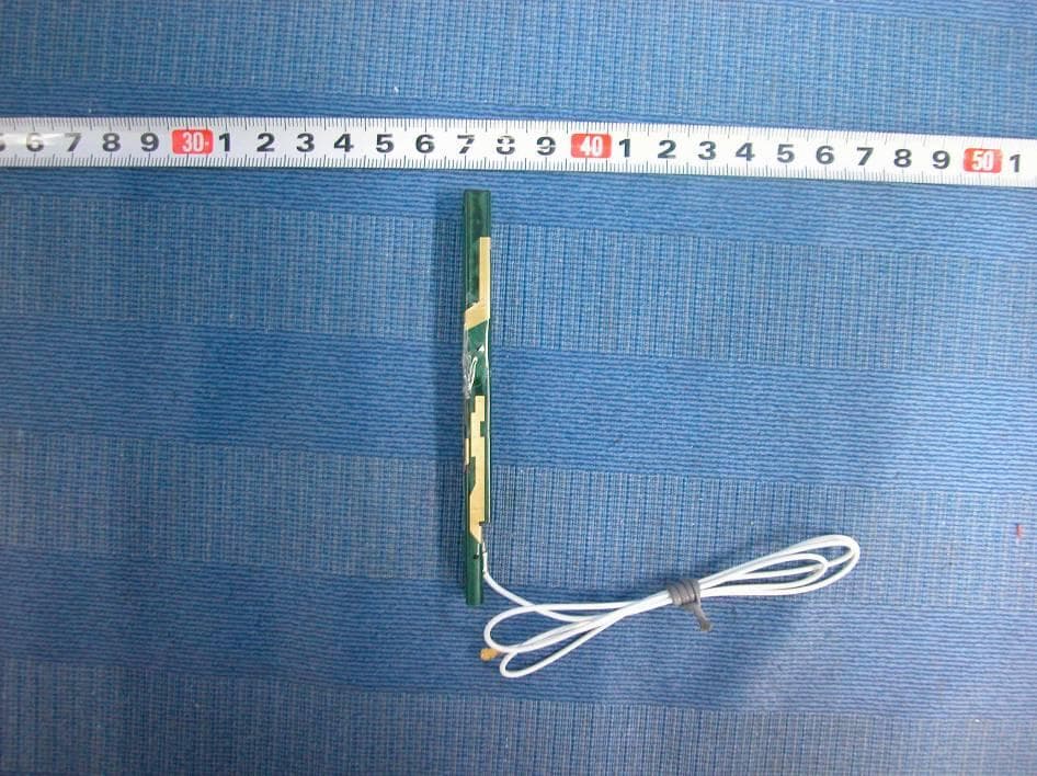
Click to zoom
Application Details
- Equipment Class
- PCB - PCS Licensed Transmitter
- Date of Grant
- Jan 08, 2011
- Application Purpose
- Original Equipment
- Date of Application
- Dec 18, 2010
- Equipment Note
- HSPA PCI Express Mini Card
- Frequency Range
- 1712.40000000 - 1752.60000000
- Company
- ZTE Corporation
- Country
- China
Documents & Files
Document Text
Text extracted from the exhibit documents filed with the FCC. Open a document above to read the original.
Users Manual
MF220 HSPA PCI Express Mini Card User Manual 2 Contents 1 Warning and Notice ......................................................... 3 2 Introduction ...................................................................... 5 2.1 Introduction ............................................................ 5 2.2 Functions ............................................................... 5 3 Installing the Software..................................................... 6 4 Functions ......................................................................... 8 4.1 Interface Introduction ............................................. 8 4.2 Connecting to the Internet .................................... 10 4.3 SMS ..................................................................... 11 4.4 Phonebook........................................................... 14 4.5 Settings ................................................................ 16 4.6 Data record .......................................................... 20 4.7 microSD card ....................................................... 20 4.8 Help ..................................................................... 21 5 FAQ ................................................................................. 22 3 1 Warning and Notice To the owner The use of electronic transmitting devices is forbidden in aircraft, at petrol stations and in hospitals. Please observe and obey all warning signs and switch off your modem in these conditions. The module may interfere with medical devices like hearing aides and pacemakers. Be aware of warning signs in places such as oil refineries or chemical factories where there are explosive gases or explosive products being processed. Modem Only use original accessories supplied by the manufacturer. Using unauthorized accessories may invalidate your warranty. Avoid using the module near or inside metallic structures or establishments that can emit electromagnetic waves. The module is not waterproof. Please keep it dry and store it in a cool place out of direct sunlight. There are no user serviceable parts. Dismantling the unit will invalidate the warranty. Operating temperature range of -10°C ~ +60°C and humidity 5%~95% are recommended. FCC Compliance This device complies with part 15 of the FCC Rules. Operation is subject to the condition that this device does not cause harmful interference. Caution: Changes or modifications not expressly approved by the manufacturer could void the user’s authority to operate the equipment. NOTE: This equipment has been tested and found to comply with the limits for a Class B digital device, pursuant to part 15 of the FCC Rules. These limits are designed to provide reasonable protection against 4 harmful interference in a residential installation. This equipment generates, uses and can radiate radio frequency energy and, if not installed and used in accordance with the instructions, may cause harmful interference to radio communications. However, there is no guarantee that interference will not occur in a particular installation. If this equipment does cause harmful interference to radio or television reception, which can be determined by turning the equipment off and on, the user is encouraged to try to correct the interference by one or more of the following measures: —Reorient or relocate the receiving antenna. —Increase the separation between the equipment and receiver. —Connect the equipment into an outlet on a circuit different from that to which the receiver is connected. —Consult the dealer or an experienced radio/ TV technician for help. The final end host device which contains this module will be labeled in a visible area with FCC ID:Q78-MF220 5 2 Introduction 2.1 Introduction There is a multi-mode 3G PCI Express Mini Card (Wireless LAN Module) in your notebook. The card works in HSPA+/HSUPA/HSDPA/UMTS/EDGE/GPRS/GSM networks. It integrates the functionality of a modem and a mobile phone (SMS), and combines mobile communication with Internet perfectly. It supports data, and SMS services through the mobile phone network, enabling you to communicate anytime and anywhere. 2.2 Functions Functions SMS, Data service, Applications management, etc. Network Standards. HSPA+/HSUPA/HSDPA/UMTS/EDGE/GPRS/GSM Transmission (Max. data rate) HSPA+: 14.4Mbps DL HSUPA: 5.76Mpbs UL 6 3 Installing the Software If you accidentally uninstall the application software, you can reinstall it by following the steps below. 1. Double click Install.exe to install, which is saved in C:\ZTE_drivers. 2. Click the Next button to continue. 3. Select the folder that you want to install the software, and you can select a different location by pressing the Change button, and then click the Next button. 7 4. The system shows the installation progress, wait a minute and click the Finish button to complete the installation. Note: If you have problems with installation after the above operation, please contact the shop or ZTE. 8 4 Functions 4.1 Interface Introduction When you want to use the Wireless LAN Module, click the “Start → Programs → Join Air → Join Air” menu to run the application software, or double click the shortcut icon to run the application software. After the application software is correctly initialized, the standby icon appears in the taskbar. Note: To use all the functions the Wireless LAN Module offers, you must insert the (U)SIM card into the device in which the Module is installed. Please refer to the manual of the device for the instruction of (U)SIM card insertion. 1. Main Interface The diagrams of the main interface of the application software: The whole interface is divided into four parts. Related functions can be executed by operation in the related areas. System information area Indicators in this area show the system status and different kinds of tips. Indicator Explanation Indication of signal strength, which is divided into 6 stages from none to the strongest. Indication of …
Text truncated - open the document above for the full version.
Attestation Statements
ZTE Corporation Zhongxing Bldg, Shenzhen Hi-tech Industrial Park Nanshan District, Shenzhen city, GuangDong Province, P.R.China 518057 Tel: 086-021-68895196 Fax: 086-021-50801070 Module Characteristics Declaration We declare that our GSM/GPRS/EDGE/WCDMA/HSDPA/HSUPA Module product Product Model: MF220 (FCC ID: Q78-MF220) has the following module characteristics: Item 1 2 3 4 5 6 7 8 Requirements Have its own RF shielding Have buffered modulation/data inputs (if such inputs are provided) Have it own power supply regulation Meet the antenna requirements of Section 15.203 Be tested in a stand-alone configuration, i.e. the antenna, AC or DC power and data input/output lines must be connected to the module but, the module must not be inside another case during testing Be labeled with its own FCC ID number, and if the FCC ID is not visible when the module is installed inside another device, then the outside of the device into which the module is installed must also display a label referring to the enclosed module. The modular transmitter is manufactured so that the user cannot influence the operation of the transmitter that will operate outside of the scope of the regulations. Address compliance with the commission’s RF exposure limits Sections 1.1310 and 2.1093. In addition, spread spectrum transmitters operating under Section 15.247 are required to address RF exposure compliance in accordance with Section 15.247(b)(4). EUT Device is equipped with Metal shielding to cover RF section. Refer to external and internal photos All inputs to the modules are buffered through logic or microprocessor inputs. Internal 1.8V and 2.8V regulator IFA Antenna on the module insert to mother board Device is tested in a test fixture in a standalone configuration FCC ID label format will be included in the filling. System ID label will by displayed on the host system Refer to “User Manual” Exhibit MPE calculation is provided to demonstrate RF compliance for mobile modular approval. Signed: Name: Royce Wang Title: Product Certification Director Date: Dec 10, 2010
Cover Letter(s)
内部公开 内部公开内部公开 内部公开▲ 本文中的所有信息归中兴通讯股份有限公司所有,未经允许,不得外传 第 1 / 1 页 ZTE CORPORATION ZTE Plaza, Keji Road South, Hi-Tech Industrial Park,Nanshan District,Shenzhen, Guangdong, 518057, P.R.China Date: Oct 12,2009 To: Federal Communications Commission, Authorization & Evaluation Division, 7435 Oakland Mills Road, Columbia, MD 21046 And American Telecommunications Certification Body, Inc. 6731 Whittier Avenue Suite C110 McLean, VA 22101 To Whom It May Concern: TMC(Telecommunication Metrology Center of MII) is authorized to act on our behalf, until otherwise notified, for applications to American Telecommunications Certification Body, Inc. (ATCB). We certify that we are not subject to denial of federal benefits, that includes FCC benefits, pur suant to Section 5301 of the Anti-Drug Abuse Act of 1988, U.S.C. 862. Further, no party, as defined in 47 CFR 1.2002 (b) to the application is subject to denial of federal benefits, that includes FCC benefits. Thank you. Regards, Royce Wang ZTE CORPORATION Tel:0755-26770345 Fa x:0755-26770347 E- Mail:[email protected]
Cover Letter(s)
内部公开▲ 本文所有信息为中兴通讯股份有限公司内部信息,未经允许,不得外传 第1页,共1页 ZTE CORPORATION ZTE Plaza, Keji Road South, Hi-Tech Industrial Park, Nanshan District, Shenzhen, Guangdong, 518057, P.R.China Date: Dec. 10, 2010 Federal Communications Commission Office of Engineering and Technology Equipment Authorization Division 7345 Oakland Mills Road Columbia, Maryland 21046 Subject: Permanent Confidentiality request for FCC ID: Q78-MF220 To Whom It May Concern, Pursuant to sections 0.457 and 0.459 of CFR 47, the applicant requests permanent confidential treatment of the following information accompanying this application: - Block Diagram - Schematics - Operational Description - BOM list/Tune-Up-Procedure The above materials contain trade secrets and proprietary information not customarily released to the public. The public disclosure of these matters might be harmful to the applicant and provide unjustified benefits to its competitors. Sincerely yours, Royce Wang ZTE CORPORATION Tel: 0755-26770345 Fax: 0755-26770347 E-Mail: [email protected]
External Photos
MF220 external photo
ID Label/Location Info
MF220 Label Location: Label
Internal Photos
MF220 internal photos
RF Exposure Info
RF exposure requirements – ZTE MF220 Dear Reviewer, The maximum measured power output is GSM 850:32.94dBm GSM 1900:30.48dBm UMTS 850: 22.61dBm UMTS 1900: 22.09dBm UMTS 1700: 22.15dBm the maximum antenna gain for integral antenna is GSM 850:-1.0dBi GSM 1900:1.2dBi UMTS 850: -1.0dBi UMTS 1900: 1.2dBi UMTS 1700: -1.2dBi The maximum permissible exposure is defined in 47 CFR 1.1310 with 1 mW/cm². The Transmitter is using external antennas that operate at 20 cm or more from nearby persons. The maximum permitted level is calculated using the general equation: S = P’ / 4R² GSM 850: P’ = 32.94dBm+(-1.0dBi)=31.94dBm=1563mW GSM1900: P’ = 30.48dBm+ 1.2dBi=31.68dBm=1472mW UMTS850: P’ = 22.61dBm+(-1.0dBi)=21.61dBm=145mW UMTS1900: P’ = 22.09dBm+1.2dBi =23.29dBm=213mW UMTS1700: P’ = 22.15dBm+(-1.2dBi) =20.95dBm=124mW R = 20cm = 3.1416 Solving for S, the power density at 20 cm is GSM 850: 0.311mW/cm² GSM1900: 0.293mW/cm² UMTS850: 0.029mW/cm² UMTS1900: 0.042mW/cm² UMTS1700: 0.025mW/cm² So the limit is kept. Best Regard. 2010-12-15 Zhang Hao Telecommunication Metrology Center of MIIT No 52 Huayuanbei Road, Haidian District Beijing P.R.China 100191
Test Report
TEST REPORT No. 2010TAR468 for ZTE CORPORATION MF220 HSPA PCI Express Mini Card Model Name: MF220 FCC ID: Q78-MF220 with Hardware Version: d21B Software Version: EN_ZTE_MF220V1.0.0B06 Issued Date: Dec 15, 2010 Note: The test results in this test report relate only to the devices specified in this report. This report shall not be reproduced except in full without the written approval of TMC Beijing. Test Laboratory: DAR accreditation (DIN EN ISO/IEC 17025): No. DGA-PL-114/01-02 FCC 2.948 Listed: No.733176 IC O.A.T.S listed: No.6629A-1 TMC Beijing, Telecommunication Metrology Center of Ministry of Industry and Information Technology 3/F Shou Xiang Technology Building, No.51 Xueyuan Road, Hai Dian District, Beijing, P. R. China,100191. Tel:+86(0)10-62304633-2604, Fax:+86(0)10-62304793, Email:[email protected], web: www.emcite.com No.2010TAR468 Page2 of 63 CONTENTS 1. TEST LABORATORY ............................................................................................................... 3 1.1. TESTING LOCATION ........................................................................................................... 3 1.2. TESTING ENVIRONMENT ................................................................................................... 3 1.3. PROJECT DATA ................................................................................................................... 3 1.4. SIGNATURE .......................................................................................................................... 3 2. CLIENT INFORMATION ........................................................................................................... 4 2.1. APPLICANT INFORMATION ................................................................................................ 4 2.2. MANUFACTURER INFORMATION ...................................................................................... 4 3. EQUIPMENT UNDER TEST (EUT) AND ANCILLARY EQUIPMENT (AE) ............................ 5 3.1. ABOUT EUT .......................................................................................................................... 5 3.2. INTERNAL IDENTIFICATION OF EUT USED DURING THE TEST ................................... 5 3.3. INTERNAL IDENTIFICATION OF AE USED DURING THE TEST ...................................... 5 3.4. GENERAL DESCRIPTION ................................................................................................... 5 4. REFERENCE DOCUMENTS .................................................................................................... 6 4.1. REFERENCE DOCUMENTS FOR TESTING....................................................................... 6 5. LABORATORY ENVIRONMENT .............................................................................................. 7 6. SUMMARY OF TEST RESULTS .............................................................................................. 8 7. TEST EQUIPMENTS UTILIZED ............................................................................................... 9 ANNEX A: MEASUREMENT RESULTS ....................................................................................... 10 A.1 OUTPUT POWER (§22.913(A)/§24.232(B)) ................................................................... 10 A.2 EMISSION LIMT (§2.1051/§24.238) ............................................................................... 16 A.3 FREQUENCY STABILITY (§2.1055/§24.235) ................................................................. 21 A.4 OCCUPIED BANDWIDTH (§2.1049(H)(I)) ........................................................................ 23 A.5 EMISSION BANDWIDTH (§22.917(B)/§24.238(B)) ......................................................... 35 A.6 BAND EDGE COMPLIANCE (§22.917(B)/§24.238(B)) ................................................... 47 A.7 CONDUCTED SPURIOUS EMISSION (§2.1057/§22.917/§24.238) ................................ 53 No.2010TAR468 Page3 of 63 1. Test Laboratory 1.1. Testing Location Company Name: TMC Beijing, Telecommunication Metrology Center of MIIT Address: 3/F Shou Xiang Technology Building, No.51 Xueyuan Road, Hai Dian District, Beijing, P. R. China Postal Code: 100191 Telephone: 00861062304633 Fax: 00861062304793 1.2. Testing Environment Normal Temperature: 15-35°C Relative Humidity: 20-75% 1.3. Project data Testing Start Date: Nov 26, 2010 Testing End Date: Dec 10, 2010 1.4. Signature Zi Xiaogang (Prepared this test report) Sun Xiangqian (Reviewed this test report) Lu Bingsong Deputy Director of the laboratory (Approved this test report) No.2010TAR468 Page4 of 63 2. Client Information 2.1. Applicant Information Company Name: ZTE CORPORATION Address /Post: ZTE Plaza, Keji Road South, Hi-Tech Industrial Park, Nanshan District, Shenzhen, Guangdong, 518057, P.R.China City: Shenzhen Postal Code: 518057 Country: China Telephone: 0086 21 68895196 Fax: 0086 21 61460600 2.2. Manufacturer Information Company Name: ZTE CORPORATION Address /Post: ZTE Plaza, Keji Road South, Hi-Tech Industrial Park, Nanshan District, Shenzhen, Guangdong, 518057, P.R.China City: Shenzhen Postal Code: 518057 Country: China Telephone: 0086 21 68895196 Fax: 0086 21 61460600 No.2010TAR468 Page5 of 63 3. Equipment Under Test (EUT) and Ancillary Equipment (AE) 3.1. About EUT Description MF220 HSPA PCI Express Mini Card Model Name MF220 FCC ID Q78-MF220 Frequency GSM 850MHz; GSM 900MHz; DCS1800MHz; PCS1900MHz; WCDMA BAND I; WCDMA BAND II; WCDMA BAND IV; WCDMA BAND V; WCDMA BAND VIII Antenna Internal Power supply Battery or Charger (AC Adaptor) Output power 25.91 dBm maximum EIRP measured for GSM1900 Extreme vol. Limits 4.8VDC to 5.2VDC (nominal: 5.0VDC) Note: Components list, please refer to documents of the manufacturer; it is also included in the original test record of Telecommunication Metrology Center of MIIT of People’s Republic of China. 3.2. Internal Identification of EUT used during the test EUT ID* SN or IMEI HW Version SW Version N01 / …
Text truncated - open the document above for the full version.
Test Report
TEST REPORT No. 2010TAR469 for ZTE CORPORATION MF220 HSPA PCI Express Mini Card Model Name: MF220 FCC ID: Q78-MF220 with Hardware Version: d21B Software Version: EN_ZTE_MF220V1.0.0B06 Issued Date: Dec 15, 2010 Note: The test results in this test report relate only to the devices specified in this report. This report shall not be reproduced except in full without the written approval of TMC Beijing. Test Laboratory: DAR accreditation (DIN EN ISO/IEC 17025): No. DGA-PL-114/01-02 FCC 2.948 Listed: No.733176 IC O.A.T.S listed: No.6629A-1 TMC Beijing, Telecommunication Metrology Center of Ministry of Industry and Information Technology 3/F Shou Xiang Technology Building, No.51 Xueyuan Road, Hai Dian District, Beijing, P. R. China,100191. Tel:+86(0)10-62304633-2604, Fax:+86(0)10-62304793, Email:[email protected], web: www.emcite.com No.2010TAR469 Page2 of 53 CONTENTS 1. TEST LABORATORY ......................................................................................................................... 3 1.1. TESTING LOCATION .................................................................................................................... 3 1.2. TESTING ENVIRONMENT ........................................................................................................... 3 1.3. PROJECT DATA .............................................................................................................................. 3 1.4. SIGNATURE ..................................................................................................................................... 3 2. CLIENT INFORMATION ................................................................................................................... 4 2.1. APPLICANT INFORMATION ....................................................................................................... 4 2.2. MANUFACTURER INFORMATION ............................................................................................ 4 3. EQUIPMENT UNDER TEST (EUT) AND ANCILLARY EQUIPMENT (AE) ............................. 5 3.1. ABOUT EUT ..................................................................................................................................... 5 3.2. INTERNAL IDENTIFICATION OF EUT USED DURING THE TEST .................................... 5 3.3. NTERNAL IDENTIFICATION OF AE USED DURING THE TEST ......................................... 5 3.4. GENERAL DESCRIPTION ............................................................................................................ 5 4. REFERENCE DOCUMENTS ............................................................................................................. 6 4.1. REFERENCE DOCUMENTS FOR TESTING ............................................................................. 6 5. LABORATORY ENVIRONMENT ..................................................................................................... 7 6. SUMMARY OF TEST RESULTS ....................................................................................................... 8 7. TEST EQUIPMENTS UTILIZED ...................................................................................................... 9 ANNEX A: MEASUREMENT RESULTS ................................................................................................ 10 A.1 OUTPUT POWER (§22.913(A)/§24.232(B)) ............................................................................... 10 A.2 EMISSION LIMT (§2.1051/§24.238) .......................................................................................... 16 A.3 FREQUENCY STABILITY (§2.1055/§24.235) ......................................................................... 22 A.4 OCCUPIED BANDWIDTH (§2.1049(H)(I)) ............................................................................... 25 A.5 EMISSION BANDWIDTH (§22.917(B)/§24.238(B)) ............................................................... 31 A.6 BAND EDGE COMPLIANCE (§22.917(B)/§24.238(B)) .......................................................... 37 A.7 CONDUCTED SPURIOUS EMISSION (§2.1057/§22.917/§24.238) ......................................... 40 No.2010TAR469 Page3 of 53 1. Test Laboratory 1.1. Testing Location Company Name: TMC Beijing, Telecommunication Metrology Center of MIIT Address: 3/F Shou Xiang Technology Building, No.51 Xueyuan Road, Hai Dian District, Beijing, P. R. China Postal Code: 100191 Telephone: 00861062304633 Fax: 00861062304793 1.2. Testing Environment Normal Temperature: 15-35°C Relative Humidity: 20-75% 1.3. Project data Testing Start Date: Nov 26, 2010 Testing End Date: Dec 10, 2010 1.4. Signature Zi Xiaogang (Prepared this test report) Sun Xiangqian (Reviewed this test report) Lu Bingsong Deputy Director of the laboratory (Approved this test report) No.2010TAR469 Page4 of 53 2. Client Information 2.1. Applicant Information Company Name: ZTE CORPORATION Address /Post: ZTE Plaza, Keji Road South, Hi-Tech Industrial Park, Nanshan District, Shenzhen, Guangdong, 518057, P.R.China City: Shenzhen Postal Code: 518057 Country: China Telephone: 0086 21 68895196 Fax: 0086 21 61460600 2.2. Manufacturer Information Company Name: ZTE CORPORATION Address /Post: ZTE Plaza, Keji Road South, Hi-Tech Industrial Park, Nanshan District, Shenzhen, Guangdong, 518057, P.R.China City: Shenzhen Postal Code: 518057 Country: China Telephone: 0086 21 68895196 Fax: 0086 21 61460600 No.2010TAR469 Page5 of 53 3. Equipment Under Test (EUT) and Ancillary Equipment (AE) 3.1. About EUT Description MF220 HSPA PCI Express Mini Card Model Name MF220 FCC ID Q78-MF220 Frequency GSM 850MHz; GSM 900MHz; DCS1800MHz; PCS1900MHz; WCDMA BAND I; WCDMA BAND II; WCDMA BAND IV; WCDMA BAND V; WCDMA BAND VIII Antenna Internal Power supply Battery or Charger (AC Adaptor) Output power 20.44 dBm maximum EIRP measured for WCDMA BAND IV Extreme vol. Limits 4.8VDC to 5.2VDC (nominal: 5.0VDC) Note: Components list, please refer to documents of the manufacturer; it is also included i…
Text truncated - open the document above for the full version.
Test Setup Photos
MF220 FCC test setup photo 1. Radiated Spurious Emission
Contact Information
Applicant
Cary Kong(Product Certification Manager)
Technical Contact
Telecommunications Metrology Center of MIITXue Zhen
[email protected]+86-10-62304633
Floor 3, Shouxiang Science Building, No 51 · Beijing · China
Test Firm
TMC-Telecommunication Metrology Center of M.I.I.TChongwen Song
Technical Specifications
| # | Rule Parts | Frequency Range | Power Output | Emission | Tolerance |
|---|---|---|---|---|---|
| 7 | 27 | 1.71 GHz - 1.75 GHz | 164.00 mW | 4M50F9W | 0.1 ppm |
Other Applications from ZTE Corporation

Q78-E1320
Oct 06, 2022Home Gateway
Equipment Class
NII - Unlicensed National Information Infrastructure TX
Q78-E3330
Sep 21, 2022Home Gateway
Equipment Class
JBP - Part 15 Class B Computing Device Peripheral
Q78-ZXV10B866V2
May 23, 2021RichMedia Box
Equipment Class
DTS - Digital Transmission System
Q78-ZXHNH298Q
Apr 22, 2021Home Gateway
Equipment Class
NII - Unlicensed National Information Infrastructure TX
Q78-ZXHNH196Q
Apr 19, 2021Home Gateway
Equipment Class
NII - Unlicensed National Information Infrastructure TX