Q78-MG166CDMA 1X WIRELESS CARD
ZTE Corporation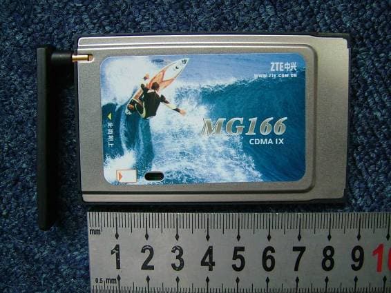
Click to zoom
Application Details
- Equipment Class
- PCB - PCS Licensed Transmitter
- Date of Grant
- Oct 26, 2005
- Application Purpose
- Original Equipment
- Date of Application
- Oct 26, 2005
- Equipment Note
- CDMA 1X WIRELESS CARD
- Frequency Range
- 1851.25000000 - 1908.75000000
- Company
- ZTE Corporation
- Country
- China
Documents & Files
Document Text
Text extracted from the exhibit documents filed with the FCC. Open a document above to read the original.
Users Manual
ZTE CDMA 1X Card User Guide 2005-6-16 ZTE Corporation http//wwwzteitcom . ZTE CDMA 1X Card User Guide Ve r s i o n : V 4 . 2 C - T Y This user guide applies to the ZTE CDMA 1X card of MC315/MC315+, MG166, and MG466. ZTE CDMA 1X Card User Guide 2005-6-16 ZTE Corporation http//wwwzteitcom Copyright Statement Copyright © 2005 by ZTE Corporation The copyright of this User Manual belongs to ZTE Corporation and under the protection of Copyright Law of the People’s Republic of China and other relative laws. No part of this publication may be excerptedreproduced, translated or utilized in any form or by any means (electronic or mechanicalincluding photocopying and microfilm) without prior written permission from ZTE Corporation. Any violation behavior will be punished. The information in the document is subject to change without notice. At the same time we reserve the right to revise or recall the User Manual. If there is anything unclear in this manual, please contact us or our agent or seller. ZTE CDMA 1X Card User Guide 2005-6-16 ZTE Corporation http//wwwzteitcom Contents 1. Introduction...............................................................................................................................1 2. Specifications ............................................................................................................................1 3. Care for your card .....................................................................................................................1 4. Features .....................................................................................................................................2 5. Setup and Uninstall ...................................................................................................................3 5.1System Requirements.........................................................................................................3 5.2Setup for Windows 2000 ....................................................................................................3 5.2.1 Setup.........................................................................................................................3 5.2.2 Uninstall ...................................................................................................................8 5.3 Setup for Windows XP........................................................................................................9 5.3.1 Setup.........................................................................................................................9 5.3.2 Uninstall .................................................................................................................13 6. The Main Window and Icons ..................................................................................................15 7. Connect/Disconnect ................................................................................................................16 8. Connection Record..................................................................................................................17 9. Voice call.................................................................................................................................18 10. Call History .............................................................................................................................19 11. Send Short Messages ..............................................................................................................20 12. Read Short Messages ..............................................................................................................21 13. Phone Book .............................................................................................................................22 14. Settings....................................................................................................................................23 15. Trouble Shooting.....................................................................................................................24 ZTE CDMA 1X Card User Guide 2005-6-16 ZTE Corporation page1 http//wwwzteitcom 1. Introduction ZTE CDMA 1X card fits into a standard Type II PC Card slot (available on most notebook PCs) and can function as a wireless network card, a modem, and a mobile phone. This card allows you to connect to the Internet, send and receive SMS messages, and make phone calls, without the need of a network cable or phone line. With the design of the R-UIM card separate from the body, ZTE CDMA 1X card can make the operation more flexible. 2. Specifications Model Item MC315 MC315+ MG166 MG466 Transmit Frequency 824~849MHz 824~849MHz 1850~1910MHz 452.5~457.5MHz Receive Frequency 869~894MHz 869~894MHz 1930~1990MHz 462.5~467.5MHz Freq. Stability FA±300Hz Dimension 86*54*5 mm Weight 33g Data Transmission MAX 153.6 kbps Voltage 3.3V from PCMCIA Slot Current Dormancy: 90mA Maximum: 850mA Transmitter Power 200mW 3. Care for your card ¾ Protect the card from liquids, dust, and excessive heat. ¾ Optimal signal strength is usually obtained when the antenna is perpendicular to the card. The antenna should bend easily. Do not forcefully bend the antenna or plugs the antenna in and out ZTE CDMA 1X card frequently.ZTE shall not be held responsible for the loss due to user’s disoperation. ¾ The ZTE CDMA 1X card should fit easily into your PC slot. Forcing the card into a slot may damage connector pins. ¾ Do not operate the ZTE CDMA 1X card near any equipment which may be susceptible to electromagnetic interference. ZTE CDMA 1X Card User Guide 2005-6-16 ZTE Corporation page2 http//wwwzteitcom 4. Features Your ZTE CDMA 1X card may need R-UIM card. Contact your provider to get the information about if your ZTE CDMA 1X card need or need not the R-UIM card. Please insert the R-UIM card to your ZTE CDMA 1X card if it needs. Insert R-UIM card to ZTE CDMA 1X card (only for those who need R-UI…
Text truncated - open the document above for the full version.
External Photos
External Photos 1. Front View of EUT 2. Back View of EUT 3. Side View of EUT
ID Label/Location Info
Label Label Location
Internal Photos
Internal Photos
RF Exposure Info
ShenZhen Electronic Product Quality Testing Center CONFORMANCE TEST REPORT FOR HUMAN EXPOSURE TO ELECTROMAGNETIC FIELDS SAR05_012 ZTE Corporation CDMA1X WIRELESS Card Type Name: MG166 FCC ID: Q78-MG166 Hardware Version: 050402 Software Version: v0.21 Date of Issue: 2005-10-25 No. SAR05-012 Page 3 of 39 Contents 1. GENERAL CONDITIONS 2. ADMINISTRATIVE DATA 2.1. Identification of the Responsible Testing Laboratory 2.2. Identification of the Responsible Testing Location(s) 2.3. Organization Item 2.4. Identification of Applicant 2.5. Identification of Manufacture 3. EQUIPMENT UNDER TEST (EUT) 3.1. Identification of the Equipment under Test 3.2. Identification of all used Test Sample of the Equipment under Test 4. OPERATIONAL CONDITIONS DURING TEST 4.1. Schematic Test Configuration 4.2. SAR Measurement System 5. CHARACTERISTICS OF THE TEST 5.1. Applicable Limit Regulations 5.2. Applicable Measurement Standards 6. LABORATORY ENVIRONMENT 7. TEST RESULTS 7.1. Dielectric Performance 7.2. Summary of Measurement Results 7.3. Conclusion 8. MEASUREMENT UNCERTAINTY 9. MAIN TEST INSTRUMENTS This Test Report consists of the following Annexes: Annex A: Accreditation Certificate Annex B: Test Layout Annex C: Sample Photographs Annex D: Graph Test Results No. SAR05-012 Page 4 of 39 1.GENERAL CONDITIONS 1.1 This report only refers to the item that has undergone the test. 1.2 This report standalone dose not constitute or imply by its own an approval of the product by the certification Bodies or competent Authorities. 1.3 This document is only valid if complete; no partial reproduction can be made without written approval of Shenzhen Electronic Product Quality Testing Center. 1.4 This report cannot be used partially or in full for publicity and/or promotional purposes without previous written approval of Shenzhen Electronic Product Quality Testing Center and the Accreditation Bodies, if it applies. No. SAR05-012 Page 5 of 39 2. Administrative Date 2.1. Identification of the Responsible Testing Laboratory Company Name: ShenZhen Electronic Product Quality Testing Center Department: Testing Department Address: Electronic Testing Building, ShaHe Road, NanShan District, ShenZhen, P. R. China Telephone: +86-0755-26628676 Fax: +86-0755-26627238 Responsible Test Lab Managers: Mr. Wang Keqin 2.2. Identification of the Responsible Testing Location(s) Company Name: ShenZhen Electronic Product Quality Testing Center Address: Electronic Testing Building, ShaHe Road, NanShan District, ShenZhen, P. R. China 2.3. Organization Item S.E.T Report No.: SAR05_012 S.E.T Project Leader: Mr. Li Sixiong S.E.T Responsible for accreditation scope: Mr. Wang Keqin Start of Testing: 2005-9-14 End of Testing: 2005-10-25 2.4. Identification of Applicant Company Name: ZTE Corporation Address: ZTE Plaza, Keji Road South, Hi-Tech, Industrial Park, Nanshan District,Shenzhen, Guangdong,P.R.China Contact person: Gongbolin Telephone: (86)755-26010631 Fax: (86)755-26010198 2.5. Identification of Manufacture Company Name: ZTE Corporation Address: ZTE Plaza, Keji Road South, Hi-Tech, Industrial Park, Nanshan District,Shenzhen, Guangdong,P.R.China Contact person: Gongbolin Telephone: (86)755-26010631 Fax: (86)755-26010198 Notes: This data is based on the information by the applicant. No. SAR05-012 Page 6 of 39 3. Equipment Under Test (EUT) 3.1. Identification of the Equipment under Test Brand Name: ZTE Type Name: MG166 Marking Name: MG166 Test frequency CDMA 1900MHz Antenna type 5.21cm Accessory Head phone Operation mode Call established Modulation mode CDMA2000 1X General description: Max. Power EIRP 0.144w(21.58dBm) 3.2. Identification of all used Test Sample of the Equipment under Test ESN Serial Number Hardware Version Software Version MIN 695F7B9A 290522130493 050402 V0.21 000000000005242 No. SAR05-012 Page 7 of 39 4 OPERATIONAL CONDITIONS DURING TEST 4.1 Schematic Test Configuration During SAR test, EUT is in Traffic Mode (Channel Allocated) at Normal Voltage Condition. A communication link is set up with a System Simulator (SS) by air link, and a call is established. The TCH is allocated to 25, 600 and 1175 respectively in the case of CDMA 1900 MHz. The EUT is commanded to operate at maximum transmitting power. The EUT shall use its internal transmitter. The antenna(s), battery and accessories shall be those specified by the manufacturer. The EUT battery must be fully charged and checked periodically during the test to ascertain uniform power output. If a wireless link is used, the antenna connected to the output of the base station simulator shall be placed at least 50 cm away from the handset. The signal transmitted by the simulator to the antenna feeding point shall be lower than the output power level of the handset by at least 35 dB. 4.2 SAR Measurement System The SAR measurement system being used is the IndexSAR SARA2 system, which consists of a Figure1. SAR Lab Test Measurement Set-up Mitsubishi RV-E2 6-axis robot arm and controller, IndexSAR probe and amplifier and SAM phantom No. SAR05-012 Page 8 of 39 Head Shape. The system is controlled remotely from a PC, which contains the software to control the robot and data acquisition equipment. The software also displays the data obtained from test scans. In operation, the system first does an area (2D) scan at a fixed depth within the liquid from the inside wall of the phantom. When the maximum SAR point has been found, the system will then carry out a 3D scan centred at that point to determine volume averaged SAR level. 4.2.1 Robot system specification The robot is used to articulate the probe to programmed positions inside the phantom head to obtain the SAR readings from the DUT. 4.2.2 Probe and amplifier specification IXP-050 Indexsar isotropic immersible SAR probe The probes are constructed using three orthogonal dipole sensors arranged on an interlocking, triangular prism core. The probes have built-in shielding against static charges and are contained within a PEEK No. SAR05-012 Page 9…
Text truncated - open the document above for the full version.
Test Report
Report No. FCC05-8031 Page 2 of 29 Table of Contents 1 Test Report Certification ...............................................................................................................4 2 General Information ......................................................................................................................5 2.1 Description of EUT ...............................................................................................................5 2.2 Objective ...............................................................................................................................5 2.3 Test Standards and Results ....................................................................................................6 2.4 List of Equipments Used .......................................................................................................6 2.5 Test Facility ...........................................................................................................................7 2.6 Environmental conditions .....................................................................................................7 3 Frequencies ...................................................................................................................................8 3.1 Frequency Blocks Available for Broadband PCS .................................................................8 3.2 Test Procedure .......................................................................................................................8 3.3 Test Setup ..............................................................................................................................9 3.4 EUT Setup and Operating Conditions...................................................................................9 3.5 Test Results ...........................................................................................................................9 4 Equivalent Isotropically Radiated Power (EIRP) Test ................................................................ 11 4.1 Limits of EIRP .................................................................................................................... 11 4.2 Test Procedure ..................................................................................................................... 11 4.3 Test Setup ............................................................................................................................ 11 4.4 EUT Setup and Operating Conditions................................................................................. 11 4.5 Test Results ......................................................................................................................... 11 5 Occupied Bandwidth ...................................................................................................................12 5.1 Definition ............................................................................................................................12 5.2 Test Procedure .....................................................................................................................12 5.3 Test Setup ............................................................................................................................12 5.4 EUT Setup and Operating Conditions.................................................................................12 5.5 Test Results .........................................................................................................................13 6 Conducted Spurious Emission at the Antenna Terminal .............................................................14 6.1 Limits of Spurious Radiation ..............................................................................................14 Report No. FCC05-8031 Page 3 of 29 6.2 Test Procedure .....................................................................................................................14 6.3 Test Setup ............................................................................................................................14 6.4 EUT Setup and Operating Conditions.................................................................................14 6.5 Test Results .........................................................................................................................15 7 Radiated Spurious Emission Test ................................................................................................18 7.1 Limits of Radiated Spurious Emission................................................................................18 7.2 Test Procedure .....................................................................................................................18 7.3 Test Setup ............................................................................................................................18 7.4 EUT Setup and Operating Conditions.................................................................................18 7.5 Test Results .........................................................................................................................19 8 Frequency Stability Test ..............................................................................................................24 8.1 Requirement of Frequency Stability ...................................................................................24 8.2 Test Procedure .....................................................................................................................24 8.3 Test Setup ............................................................................................................................24 8.4 EUT Setup and Operating Conditions.................................................................................25 8.5 Test Results .......................................................................................…
Text truncated - open the document above for the full version.
Test Setup Photos
Test Setup Photos 1. Conducted 2. Radiated
Contact Information
Applicant
Cary Kong(Product Certification Manager)
Test Firm
ShenZhen Electronic Product Quality Testing CenterXingsun Lin
Technical Specifications
| # | Rule Parts | Frequency Range | Power Output | Emission | Tolerance |
|---|---|---|---|---|---|
| 1 | 24E | 1.85 GHz - 1.91 GHz | 144.00 mW | 1M25F9W | 0.0143600000 ppm |
Other Applications from ZTE Corporation

Q78-E1320
Oct 06, 2022Home Gateway
Equipment Class
NII - Unlicensed National Information Infrastructure TX
Q78-E3330
Sep 21, 2022Home Gateway
Equipment Class
JBP - Part 15 Class B Computing Device Peripheral
Q78-ZXV10B866V2
May 23, 2021RichMedia Box
Equipment Class
DTS - Digital Transmission System
Q78-ZXHNH298Q
Apr 22, 2021Home Gateway
Equipment Class
NII - Unlicensed National Information Infrastructure TX
Q78-ZXHNH196Q
Apr 19, 2021Home Gateway
Equipment Class
NII - Unlicensed National Information Infrastructure TX