Q78-VDF225Mobile Phone
ZTE Corporation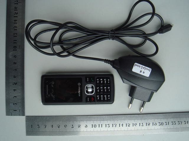
Click to zoom
Application Details
- Equipment Class
- PCE - PCS Licensed Transmitter held to ear
- Date of Grant
- Jul 18, 2007
- Application Purpose
- Original Equipment
- Date of Application
- Jul 18, 2007
- Equipment Note
- Mobile Phone
- Frequency Range
- 824.20000000 - 848.80000000
- Company
- ZTE Corporation
- Country
- China
Documents & Files
Document Text
Text extracted from the exhibit documents filed with the FCC. Open a document above to read the original.
Users Manual
Vodafone 225 User Manual Notice Copyright ©. 2007 ZTE Ltd. All Rights Reserved Your Vodafone 225 is made exclusively for Vodafone by ZTE Ltd. No part of this manual may be reproduced or transmitted in any form or by any means without prior written consent of ZTE Ltd. Trademarks VODAFONE and the Vodafone logos are trade marks of the Vodafone Group. Notice The information in this manual is subject to change without notice. Every effort has been made in the preparation of this manual to ensure accuracy of the contents, but all statements, information, and recommendations in this manual do not constitute a warranty of any kind, expressed or implied. Please read the safety precautions carefully to ensure the correct and safe use of your mobile phone. For detailed information, refer to the section "Important Safety Precautions". ZTE Ltd. Address: ZTE Plaza, Keji Road South, Hi-tech Industrial Park,Nanshan District, Shenzhen, P. R. China Postal Code: 518057 Website: http://www.zte.com.cn Important safety precautions Failure to comply with the following precautions may be dangerous or illegal. 4 Road safety Full attention should be given to driving at all times in order to reduce the risk of an accident. Using a phone while driving causes distraction and can lead to an accident. You should comply with local laws and regulations restricting the use of wireless devices while driving. Switch off the phone when refuelling Do not use the phone at a refuelling point (service station) or near fuels or chemicals. Aircraft Mobile phones can cause interference. Consult airport and airline staff about the use of the phone on aircraft. Switch off the phone whenever you are instructed to do so. Switch off the phone near all medical equipment Hospitals or health care facilities may be using equipment that could be sensitive to external radio frequency energy. Follow any regulations or rules in force. Interference All Mobile phones may be subject to interference, which could affect their performance. Be aware of special regulations Meet any special regulations in force in any area and always switch off your phone whenever it is forbidden to use it, or when it may cause interference or danger. 5 Water resistance Your phone is not water-resistant. Keep it dry. Sensible use Use only in the normal position (held to the ear). Emergency calls Key in the emergency number for your present location, then press . Keep your phone away from small children Keep the phone and all its parts, including accessories, out of the reach of small children. The product contains small parts with sharp edges that may cause injury or which may become detached and create a choking hazard. Accessories and batteries Use only ZTE-approved batteries and accessories. Use of any unauthorised accessories could damage you or your phone and may be dangerous. Dispose of used batteries according to the manufacturer's instructions. At very high volume, prolonged listening to a mobile phone can damage your hearing. Qualified service Do not attempt to disassemble your product or its accessories. Only qualified service personnel may repair your phone. 6 Health and safety information SAR certification information THIS MODEL MEETS INTERNATIONAL GUIDELINES FOR EXPO-SURE TO RADIO WAVES. Your mobile phone is a radio transmitter and receiver. It is designed not to exceed the limits for exposure to radio waves recommended by international guidelines. The guidelines were developed by independent scientific organisation ICNIRP and include margins designed to assure the protection of all persons, regardless of age and health. This guideline uses a unit of measurement known as Specific Absorption Rate, or SAR. The SAR limit for mobile devices is1.6 W/kg and the highest SAR value for this device when tested at the ear was 1.549W/kg. 1 1. The tests are carried out in accordance with international guidelines for testing. As SAR is measured utilising the device's highest transmitting power, the actual SAR of this device while operating is typically below that indicated above. This is due to automatic changes to the power level of the device to ensure it only uses the minimum level required to reach the network. The World Health Organization has stated that present scientific information does not indicate the need for any special precautions for the use of mobile devices. Body-worn operations are restricted to belt-clips, holsters or similar accessories that have no metallic component in the assembly and that provide at least 1.5 cm separation between the device, including its antenna, and the user's body. 7 Precautions when using batteries z Never use a charger or battery that is damaged in any way. z Use the battery only for its intended purpose. z If you use the phone near the network's base station, it uses less power. Talk and standby time are greatly affected by the signal strength on the cellular network and the parameters set by the network operator. z Battery charging time depends on the remaining battery charge, the type of battery, and the charger used. The battery can be charged and is charged hundreds of times, but it will gradually wear out. When the peration time is noticeably shorter than normal, it is time to buy a new battery. z If left unused, a fully charged battery will discharge itself over time. z Use only ZTE-approved batteries, and recharge your battery only with ZTE-approved chargers. Disconnect the charger from the power source when it is not in use. z Extreme temperatures will affect the charging capacity of your battery: it may require cooling or warming first. z Do not leave the battery in hot or cold places because the capacity and lifetime of the battery will be reduced. Try to keep the battery at room temperature. A phone with a hot or cold battery may not work temporarily, even when the battery is fully charged. Li-ion batteries are particularly affected by temperatures below 0°C (32°F). 8 z Do not short-circuit the battery. Accident…
Text truncated - open the document above for the full version.
Cover Letter(s)
Jul. 11 2007 Federal Communications Commission Authorization and Evaluation Division 7435 Oakland Mills Road Columbia, MD 21046 Confidentiality Request Pursuant to Sections 0.457 and 0.459 of the Commission’s Rules, we, ZTE CORPORATION, hereby request confidential treatment of information accompanying this Application () as outlined below: Exhibit Type File Name Block Diagram, Block Diagram.pdf Schematics SCH.pdf Operational Description Operational Description.pdf Parts List PART_LIST.pdf TuneUp Info Tune-up.pdf The above materials contain trade secrets and proprietary information not customarily released to the public. The public disclosure of these matters might be harmful to us, ZTE CORPORATION, and provide unjustified benefits to its competitors. We, ZTE CORPORATION, understand that pursuant to Rule 0.457, disclosure of this Application (FCC ID: Q78-VDF225 ) and all accompanying documentation will not be made before the date of the Grant for this application. Sincerely Yours, Li dezi Jul. 11 2007 ZTE CORPORATION Q78-VDF225
External Photos
Report No. FCC07-8036 Page 26 of 32 Appendix IPhotographs of the EUT 1. Appearance of the MS
ID Label/Location Info
ZTE中兴 Vodafone 225 GSM Dual-band Digital Mobile Phone FCC ID:Q78-VDF225 IMEI NO:357308010000269 ZTE CORPORATION
Internal Photos
Report No. FCC07-8036 Page 27 of 32 2. Inside of the MS Report No. FCC07-8036 Page 28 of 32 Report No. FCC07-8036 Page 29 of 32 Report No. FCC07-8036 Page 30 of 32
RF Exposure Info
Report No: SH07050013S01 Page 3 of 53 Contents 1. GENERAL CONDITIONS 2. ADMINISTRATIVE DATA 2.1. Identification of the Responsible Testing Laboratory 2.2. Identification of the Responsible Testing Location(s) 2.3. Organization Item 2.4. Identification of Applicant 2.5. Identification of Manufacture 3. EQUIPMENT UNDER TEST (EUT) 3.1. Identification of the Equipment under Test 3.2. Identification of all used Test Sample of the Equipment under Test 4. OPERATIONAL CONDITIONS DURING TEST 4.1. Schematic Test Configuration 4.2. SAR Measurement System 5. CHARACTERISTICS OF THE TEST 5.1. Applicable Limit Regulations 5.2. Applicable Measurement Standards 6. LABORATORY ENVIRONMENT 7. TEST RESULTS 7.1. Dielectric Performance 7.2. Summary of Measurement Results 7.3. Conclusion 8. MEASUREMENT UNCERTAINTY 9. MAIN TEST INSTRUMENTS This Test Report consists of the following Annexes: Annex A: Accreditation Certificate Annex B: Test Layout Annex C: Sample Photographs Annex D: Graph Test Results Annex E: System Performance Check Data Report No: SH07050013S01 Page 4 of 53 1.GENERAL CONDITIONS 1.1 This report only refers to the item that has undergone the test. 1.2 This report standalone does not constitute or imply by its own an approval of the product by the certification Bodies or competent Authorities. 1.3 This document is only valid if complete; no partial reproduction can be made without written approval of Shenzhen Morlab Communications Technology Co., Ltd. 1.4 This report cannot be used partially or in full for publicity and/or promotional purposes without previous written approval of Shenzhen Morlab Communications Technology Co., Ltd. and the Accreditation Bodies, if it applies. Report No: SH07050013S01 Page 5 of 53 2. Administrative Date 2.1. Identification of the Responsible Testing Laboratory Company Name: Shenzhen Morlab Communications Technology Co.,Ltd. Department: Testing Department Address: 3Fl, Electronic Testing Building, ShaHe Road, NanShan District, Shenzhen, P. R. China Telephone: +86 755 86130268 Fax: +86 755 86130218 Responsible Test Lab Managers: Mr. Shu Luan 2.2. Identification of the Responsible Testing Location(s) Company Name: Shenzhen Electronic Product Quality Testing Center Morlab Laboratory Address: 3Fl, Electronic Testing Building, ShaHe Road, NanShan District, Shenzhen, P. R. China 2.3. Organization Item Morlab Report No.: SH07050013S01 Morlab Project Leader: Mr. Yang Jinhua Morlab Responsible for Accreditation scope: Mr. Shu Luan Start of Testing: 2007-06-21 End of Testing: 2007-06-22 2.4. Identification of Applicant Company Name: ZTE CORPORATION Address: Zhongxing Bldg, Hi-Tech Park, NanShan, Shenzhen, P.R.China Contact person: LI.DZ Telephone: +86-021-68895196 Fax: +86-021-50801070 2.5. Identification of Manufacture Company Name: ZTE CORPORATION Address: Zhongxing Bldg, Hi-Tech Park, NanShan, Shenzhen, P.R.China Contact person: LI.DZ Telephone: +86-021-68895196 Fax: +86-021-50801070 Notes: This data is based on the information offered by the applicant. Report No: SH07050013S01 Page 6 of 53 3. Equipment Under Test (EUT) 3.1. Identification of the Equipment under Test Brand Name: Vodafone Type Name: Vodafone 225 Marking Name: Vodafone 225 Test frequency GSM 850MHz PCS 1900MHz Development Stage Identical prototype Accessories Charger, Battery Battery Model Li3706T42P3h383857 Battery specification 3.7V 670 mAh Antenna type Integrated Operation mode Call established Modulation mode GMSK General description: Max. Power(EIRP) 0.769W Cellular 850MHz 0.393W PCS 1900MHz 3.2. Identification of all used Test Sample of the Equipment under Test EUT Code Serial Number Hardware Version Software Version IMEI B01 N.A. g3dB P108A2V1.0.0B01 356735010000664 NOTE: 1. The EUT consists of Hand Telephone Set and normal options: Charger, Lithium Battery as listed above. 2. Please refer to Appendix C for the photographs of the EUT. For a more detailed features description of the EUT, please refer to its User’s Manual. Report No: SH07050013S01 4 OPERATIONAL CONDITIONS DURING TEST 4.1 Schematic Test Configuration During SAR test, EUT is in Traffic Mode (Channel Allocated) at Normal Voltage Condition. A communication link is set up with a System Simulator (SS) by air link, and a call is established. The TCH is allocated to 0, 62 and 124 respectively in the case of GSM 900 MHz, or to 512, 700 and 885 respectively in the case of DCS 1800 MHz. The EUT is commanded to operate at maximum transmitting power. The EUT shall use its internal transmitter. The antenna(s), battery and accessories shall be those specified by the manufacturer. The EUT battery must be fully charged and checked periodically during the test to ascertain uniform power output. If a wireless link is used, the antenna connected to the output of the base station simulator shall be placed at least 50 cm away from the handset. The signal transmitted by the simulator to the antenna feeding point shall be lower than the output power level of the handset by at least 35 dB. 4.2 SAR Measurement System The SAR measurement system being used is the COMOSAR Test Bench, which consists of a Figure1. SAR Lab Test Measurement Set-up KUKA 6-axis robot arm and controller, Antennessa probe with no amplifier and SAM phantom. The system is controlled remotely from a PC, which contains the software to control most of the bench devices and stores measurement data. The software also displays the data obtained from test scans, Page 7 of 53 Report No: SH07050013S01 and determines the averaged SAR values (averaging region 1 gram or 10 gram) for compliance testing. In operation, the system first does an area (2D) scan at a fixed depth within the liquid from the inside wall of the phantom. When the maximum SAR point has been found, the system will then carry out a 3D scan centered at that point to determine volume averaged SAR level. 4.2.1 Robot system specification The robot is used to articulate the probe to programmed positions inside the phantom head to obtain th…
Text truncated - open the document above for the full version.
RF Exposure Info
Report No: SH07050012S01 Page 3 of 77 Contents 1. GENERAL CONDITIONS 2. ADMINISTRATIVE DATA 2.1. Identification of the Responsible Testing Laboratory 2.2. Identification of the Responsible Testing Location(s) 2.3. Organization Item 2.4. Identification of Applicant 2.5. Identification of Manufacture 3. EQUIPMENT UNDER TEST (EUT) 3.1. Identification of the Equipment under Test 3.2. Identification of all used Test Sample of the Equipment under Test 4. OPERATIONAL CONDITIONS DURING TEST 4.1. Schematic Test Configuration 4.2. SAR Measurement System 5. CHARACTERISTICS OF THE TEST 5.1. Applicable Limit Regulations 5.2. Applicable Measurement Standards 6. LABORATORY ENVIRONMENT 7. TEST RESULTS 7.1. Dielectric Performance 7.2. Summary of Measurement Results 7.3. Conclusion 8. MEASUREMENT UNCERTAINTY 9. MAIN TEST INSTRUMENTS This Test Report consists of the following Annexes: Annex A: Accreditation Certificate Annex B: Test Layout Annex C: Sample Photographs Annex D: Graph Test Results Annex E: System Performance Check Data Report No: SH07050012S01 Page 4 of 77 1.GENERAL CONDITIONS 1.1 This report only refers to the item that has undergone the test. 1.2 This report standalone does not constitute or imply by its own an approval of the product by the certification Bodies or competent Authorities. 1.3 This document is only valid if complete; no partial reproduction can be made without written approval of Shenzhen Morlab Communications Technology Co., Ltd. 1.4 This report cannot be used partially or in full for publicity and/or promotional purposes without previous written approval of Shenzhen Morlab Communications Technology Co., Ltd. and the Accreditation Bodies, if it applies. Report No: SH07050012S01 Page 5 of 77 2. Administrative Date 2.1. Identification of the Responsible Testing Laboratory Company Name: Shenzhen Morlab Communications Technology Co.,Ltd. Department: Testing Department Address: 3Fl, Electronic Testing Building, ShaHe Road, NanShan District, Shenzhen, P. R. China Telephone: +86 755 86130268 Fax: +86 755 86130218 Responsible Test Lab Managers: Mr. Shu Luan 2.2. Identification of the Responsible Testing Location(s) Company Name: Shenzhen Electronic Product Quality Testing Center Morlab Laboratory Address: 3Fl, Electronic Testing Building, ShaHe Road, NanShan District, Shenzhen, P. R. China 2.3. Organization Item Morlab Report No.: SH07050012S01 Morlab Project Leader: Mr. Yang Jinhua Morlab Responsible for Accreditation scope: Mr. Shu Luan Start of Testing: 2007-05-28 End of Testing: 2007-06-01 2.4. Identification of Applicant Company Name: ZTE CORPORATION Address: Zhongxing Bldg, Hi-Tech Park, NanShan, Shenzhen, P.R.China Contact person: Li.dz Telephone: +86-021-68895196 Fax: +86-021-50801070 2.5. Identification of Manufacture Company Name: ZTE CORPORATION Address: Zhongxing Bldg, Hi-Tech Park, NanShan, Shenzhen, P.R.China Contact person: Li.dz Telephone: +86-021-68895196 Fax: +86-021-50801070 Notes: This data is based on the information offered by the applicant. Report No: SH07050012S01 Page 6 of 77 3. Equipment Under Test (EUT) 3.1. Identification of the Equipment under Test Brand Name: Vodafone Type Name: Vodafone 125 Marking Name: Vodafone 125 Test frequency Cellular 850MHz PCS 1900MHz Development Stage Identical prototype Accessories Charger, Battery Battery Model Li3706T42P3h383857 Battery specification 3.7V 670 mAh Antenna type Integrated Operation mode Call established Modulation mode GMSK General description: Max. Power(EIRP) 0.601W Cellular 850MHz 0.982W PCS 1900MHz 3.2. Identification of all used Test Sample of the Equipment under Test EUT Code Serial Number Hardware Version Software Version IMEI SH07050012a01 N.A. g3dB P108A1V1.0.0B01 357306010000126 NOTE: 1. The EUT consists of Hand Telephone Set and normal options: Charger, Lithium Battery as listed above. 2. Please refer to Appendix C for the photographs of the EUT. For a more detailed features description of the EUT, please refer to its User’s Manual. Report No: SH07050012S01 Page 7 of 77 4 OPERATIONAL CONDITIONS DURING TEST 4.1 Schematic Test Configuration During SAR test, EUT is in Traffic Mode (Channel Allocated) at Normal Voltage Condition. A communication link is set up with a System Simulator (SS) by air link, and a call is established. The TCH is allocated to 0, 62 and 124 respectively in the case of GSM 900 MHz, or to 512, 700 and 885 respectively in the case of DCS 1800 MHz. The EUT is commanded to operate at maximum transmitting power. The EUT shall use its internal transmitter. The antenna(s), battery and accessories shall be those specified by the manufacturer. The EUT battery must be fully charged and checked periodically during the test to ascertain uniform power output. If a wireless link is used, the antenna connected to the output of the base station simulator shall be placed at least 50 cm away from the handset. The signal transmitted by the simulator to the antenna feeding point shall be lower than the output power level of the handset by at least 35 dB. 4.2 SAR Measurement System The SAR measurement system being used is the COMOSAR Test Bench, which consists of a Figure1. SAR Lab Test Measurement Set-up KUKA 6-axis robot arm and controller, Antennessa probe with no amplifier and SAM phantom. The system is controlled remotely from a PC, which contains the software to control most of the bench devices and stores measurement data. The software also displays the data obtained from test scans, Report No: SH07050012S01 Page 8 of 77 and determines the averaged SAR values (averaging region 1 gram or 10 gram) for compliance testing. In operation, the system first does an area (2D) scan at a fixed depth within the liquid from the inside wall of the phantom. When the maximum SAR point has been found, the system will then carry out a 3D scan centered at that point to determine volume averaged SAR level. 4.2.1 Robot system specification The robot is used to articulate the probe to programmed positions inside t…
Text truncated - open the document above for the full version.
Test Report
Report No. FCC07-8036 Page 1 of 32 FCC Part 22H&24E TEST REPORT of GSM Dual-band Digital Mobile Phone FCC ID Q78-VDF225 Model No. Vodafone 225 Serial No. 357308010000269 Report No. FCC07-8036 Date July 10, 2007 Prepared for ZTE Corporation Zhongxing Bldg, Hi-Tech Park, Nanshan, Shenzhen, P.R.China Prepared by ShenZhen Electronic Product Quality Testing Center Electronic Testing Building, Shahe Road, Xili, Nanshan District, ShenZhen, 518055, P.R.China Tel: 86 755 26627338 Fax: 86 755 26627238 This test report consists of 32 pages in total. It may be duplicated completely for legal use with the approval of the applicant. It should not be reproduced except in full, without the written approval of our laboratory. The client should not use it to claim product endorsement by SET. The test results in the report only apply to the tested sample. The test report shall be invalid without all the signatures of testing engineers, reviewer and approver. Report No. FCC07-8036 Page 2 of 32 Table of Contents 1 Test Report Certification ............................................................................................................... 3 2 General Information ...................................................................................................................... 4 2.1 Description of EUT ............................................................................................................... 4 2.2 Objective ............................................................................................................................... 4 2.3 Test Standards and Results .................................................................................................... 5 2.4 List of Equipments Used ....................................................................................................... 6 2.5 Test Facility ........................................................................................................................... 6 2.6 Environmental conditions ..................................................................................................... 6 3 Transmitter Radiated Power (EIRP/ERP) Test.............................................................................. 7 3.1 Limits of EIRP/ERP .............................................................................................................. 7 3.2 Test Procedure ....................................................................................................................... 7 3.3 Test Setup .............................................................................................................................. 8 3.4 EUT Setup and Operating Conditions................................................................................... 8 3.5 Test Results............................................................................................................................ 9 4 Radiated Spurious Emission Test ................................................................................................ 13 4.1 Limits of Radiated Spurious Emission................................................................................ 13 4.2 Test Procedure ..................................................................................................................... 13 4.3 Test Setup ............................................................................................................................ 13 4.4 EUT Setup and Operating Conditions................................................................................. 13 4.5 Test Results.......................................................................................................................... 14 Appendix IPhotographs of the EUT.............................................................................................. 26 Appendix IIPhotographs of the Test Configuration ...................................................................... 31 Repon No. FCC07-8036 Gi Test Report Certification Product: FCC ID: Model No.: Applicant: Applicant Address: Manufacturer: Manufacturer Address: Test Standards: Test Resqlt: CS\4 Dual-band Digiral \Iobi]e Phonc Q78-VDr225 \bdafonc 225 ZTE Corporation Zhongxing Bldg, IJi-Tech Pa.rk, Nanshan, Shenzhen. P.R.China ZfE Corporation lhongxing Bldg. Hi-Tech Park. Nanshan. Shenzhen. PR.China 47 CfR Pafi 2 ,17 CFR Pafi 12. Subpart H ,17 CFR Part 2:1. Subparl F- PASS We, Shenzhen Electronic Product Quality Testing Center. hereby certiry that the submitled samples of the above item, as detailed in chapter 2.1 ofthis report, has been tested in our facility. The test record, data evaluation and test configuration represented herein are true and accurate accounts of measurements of the sample's EMC characteristics under the conditions herein specified. Tested by: , Date: Checked by: z?/7 Approved by: ,/1 Date: / *l 'o w/ Report No. FCC07-8036 Page 4 of 32 2 General Information 2.1 Description of EUT Description: GSM Dual-band Digital Mobile Phone Model No.: VODAFONE 225 Emission Designator: 300KGXW Modulation: GSM Frequency: GSM850, Tx: 824.20-848.80MHz; Rx: 869.20-893.80MHz GSM1900, Tx: 1850.20-1909.80MHz; Rx: 1930.20MHz-1989.80MHz Power: 2W for GSM850; 1W for GSM1900 Serial No.: N.A. Hardware Version: g3dB Software Version: P108A1V1.0.0B01 Battery Voltage: Normal, 3.7V; High, 4.2V; Low, 3.6V NOTE: 1. The EUT is Quad-band GSM mobile phone which supports GSM 850MHz and 1900MHz bands. Both Cellular 850MHz and PCS 1900MHz bands were tested in this report. 2. Please refer to Appendix I for the photographs of the EUT. For a more detailed features description about the EUT, please refer to User’s Manual. 3. VODAFONE 225 is identical to VODAFONE 125 except the LCD screen. The LCD screen of VODAFONE 125 is black and white, while it is colorful for VODAFONE 225. VODAFONE 125 has passed the FCC tests, please refer to the test report: FCC07-8033 and FCC07-8034. EIRP and Radiated Spurious Emission were…
Text truncated - open the document above for the full version.
Test Report
Report No. FCC07-8034 Page 1 of 58 FCC Part 22H&24E TEST REPORT of GSM Dual-band Digital Mobile Phone FCC ID Q78-vodafone125 Model No. Vodafone 125 Serial No. 356736010000258 Report No. FCC07-8034 Date June 20, 2007 Prepared for ZTE Corporation Zhongxing Bldg, Hi-Tech Park, Nanshan, Shenzhen, P.R.China Prepared by ShenZhen Electronic Product Quality Testing Center Electronic Testing Building, Shahe Road, Xili, Nanshan District, ShenZhen, 518055, P.R.China Tel: 86 755 26627338 Fax: 86 755 26627238 This test report consists of 58 pages in total. It may be duplicated completely for legal use with the approval of the applicant. It should not be reproduced except in full, without the written approval of our laboratory. The client should not use it to claim product endorsement by SET. The test results in the report only apply to the tested sample. The test report shall be invalid without all the signatures of testing engineers, reviewer and approver. Report No. FCC07-8034 Page 2 of 58 Table of Contents 1 Test Report Certification ............................................................................................................... 4 2 General Information ...................................................................................................................... 5 2.1 Description of EUT ............................................................................................................... 5 2.2 Objective ............................................................................................................................... 5 2.3 Test Standards and Results .................................................................................................... 6 2.4 List of Equipments Used ....................................................................................................... 7 2.5 Test Facility ........................................................................................................................... 7 2.6 Environmental conditions ..................................................................................................... 7 3 Frequencies.................................................................................................................................... 8 3.1 Frequency Blocks Available for Cellular Service ................................................................. 8 3.2 Frequency Blocks Available for Broadband PCS ................................................................. 8 3.3 Test Procedure ....................................................................................................................... 8 3.4 Test Setup .............................................................................................................................. 9 3.5 EUT Setup and Operating Conditions................................................................................... 9 3.6 Test Results.......................................................................................................................... 10 4 Conducted RF Output Power Test ............................................................................................... 12 4.1 RF Power Output Test Requirement ................................................................................... 12 4.2 Test Procedure ..................................................................................................................... 12 4.3 Test Setup ............................................................................................................................ 12 4.4 EUT Setup and Operating Conditions................................................................................. 12 4.5 Test Results.......................................................................................................................... 13 5 Occupied Bandwidth Test ........................................................................................................... 17 5.1 Definition ............................................................................................................................ 17 5.2 Test Procedure ..................................................................................................................... 17 5.3 Test Setup ............................................................................................................................ 17 5.4 EUT Setup and Operating Conditions................................................................................. 17 5.5 Test Results.........................…
Text truncated - open the document above for the full version.
Contact Information
Applicant
Cary Kong(Product Certification Manager)
Test Firm
ShenZhen Electronic Product Quality Testing CenterXingsun Lin
Technical Specifications
| # | Rule Parts | Frequency Range | Power Output | Emission | Tolerance |
|---|---|---|---|---|---|
| 2 | 22H | 824.2 MHz - 848.8 MHz | 769.00 mW | 300KGXW | 0.02 ppm |
Other Applications from ZTE Corporation

Q78-E1320
Oct 06, 2022Home Gateway
Equipment Class
NII - Unlicensed National Information Infrastructure TX
Q78-E3330
Sep 21, 2022Home Gateway
Equipment Class
JBP - Part 15 Class B Computing Device Peripheral
Q78-ZXV10B866V2
May 23, 2021RichMedia Box
Equipment Class
DTS - Digital Transmission System
Q78-ZXHNH298Q
Apr 22, 2021Home Gateway
Equipment Class
NII - Unlicensed National Information Infrastructure TX
Q78-ZXHNH196Q
Apr 19, 2021Home Gateway
Equipment Class
NII - Unlicensed National Information Infrastructure TX