Q78-ZTEA16GSM DUAL-BAND DIGITAL MOBILE P
ZTE Corporation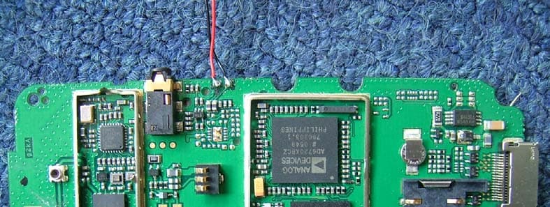
Click to zoom
Application Details
- Equipment Class
- PCE - PCS Licensed Transmitter held to ear
- Date of Grant
- Apr 25, 2006
- Application Purpose
- Original Equipment
- Date of Application
- Apr 25, 2006
- Equipment Note
- GSM DUAL-BAND DIGITAL MOBILE P
- Frequency Range
- 1850.20000000 - 1909.80000000
- Company
- ZTE Corporation
- Country
- China
Documents & Files
Document Text
Text extracted from the exhibit documents filed with the FCC. Open a document above to read the original.
Users Manual
1 ZTE CORPORATION ZTE A16 GSM Dual-band GPRS Digital Mobile Phone User Manual 2 Copyright © 2006 by ZTE Corporation All rights reserved. No part of this publication may be excerp ted, reproduced, translated or utilized in any form or by any means, electronic or mechanical, including photocopying and microfilm, without the prior written permission of ZTE Corporation. ZTE operates a policy of continuous devel opment. We reserve the right to update the technical specifications in this doc ument at any time without prior notice. Edition: 1 st edition, Mar., 2006 SW Edition: P103A2DV1.0.0B04 3 Contents 1 GENERAL INFORMATION........................................................1 1.1 W ELCOME ................................................................................1 1.2 S ECURITY .................................................................................1 1.3 S AFETY P RECAUTIONS ..............................................................2 2 GETTING STARTED....................................................................9 2.1 KEY D EFINITION .......................................................................9 2.2 D ISPLAY S YMBOLS .................................................................11 2.3 T ECHNICAL P ARAMETERS .......................................................12 2.4 B ATTERY .................................................................................13 2.4.1 Removing & Installi ng the Battery.................................13 2.4.2 Charging the Battery......................................................15 2.5 C ONNECTING TO THE N ETWORK .............................................17 4 2.5.1 SIM Card ....................................................................... 17 2.5.2 Inserting & Removing SIM Card................................... 18 2.5.3 Power on/off Your Phone............................................... 18 2.5.4 Unlocking the SIM Card and Mobile Phone ................. 19 2.5.5 Connecting to the Network ............................................ 20 3 BASIC OPER ATIONS ............................................................... 21 3.1 M AKING A C ALL .................................................................... 21 3.2 A NSWERING A C ALL .............................................................. 24 3.3 C ALL M ENU ........................................................................... 24 4 FUNCTION MENU .................................................................... 26 4.1 U SAGE AND S TRUCTURE OF F UNCTION M ENU ...................... 26 4.2 P HONE T M ENUS ..................................................................... 27 4.2.1 Calls .............................................................................. 27 4.2.2 Diverts ........................................................................... 29 5 4.2.3 Firewall ..........................................................................31 4.3 P ROFILES ................................................................................33 4.4 F AVORITE ................................................................................35 4.5 S ETTINGS ................................................................................36 4.5.1 Phone Settings................................................................37 4.5.2 Display Settings .............................................................37 4.5.3 Clock Settings.................................................................37 4.5.4 Call Settings ...................................................................38 4.5.5 Network Settings ............................................................39 4.5.6 Security Settings .............................................................39 4.5.7 Fact. Settings..................................................................42 4.6 M ESSAGE ................................................................................43 4.7 G AMES ....................................................................................48 4.8 T OOLKIT .................................................................................49 4.8.1 Alarm Clock ...................................................................50 4.8.2 Calculator ......................................................................51 6 4.8.3 Stopwatch ...................................................................... 51 4.8.4 World Clock................................................................... 52 4.9 WAP ...................................................................................... 52 4.10 STK (SIM T OOLKIT ) ............................................................. 55 4.11 N AMES ................................................................................... 56 4.11.1 Adding New Name......................................................... 58 4.11.2 Editing ........................................................................... 59 4.11.3 Viewing ............................. Error! Bookmark not defined. 4.11.4 Searching....................................................................... 59 4.11.5 Deleting One Record ..................................................... 60 4.11.6 Making an IP Call ......................................................... 60 4.11.7 Sending Message .............. Error! Bookmark not defined. 4.11.8 Settings .......................................................................... 60 4.11.9 Sending Name Card ...................................................... 61 4.11.10 One-touch Dialing............ Error! Bookmark not defined. 7 5 TEXT INPUT ...............................................................................62 5.1 O VERVIEW ..............................................................................62 5.2 KEYBOARD D EFINITION ..........................................................62 5.3 A LPHABET AND N UMERIC I NPUT ............................................63 6 TROUBLESHOOTING .............…
Text truncated - open the document above for the full version.
Cover Letter(s)
APR 18, 2006 Federal Communications Commission Authorization and Evaluation Division 7435 Oakland Mills Road Columbia, MD 21046 Confidentiality Request Pursuant to Sections 0.457 and 0.459 of the Commission’s Rules, we, ZTE CORPORATION, hereby request confidential treatment of information accompanying this Application (FCC ID: Q78-ZTEA16) as outlined below: Circuit Diagram, Block Diagram, PCB Layout Bom/Part List The above materials contain trade secrets and proprietary information not customarily released to the public. The public disclosure of these matters might be harmful to us, ZTE CORPORATION, and provide unjustified benefits to its competitors. We, ZTE CORPORATION, understand that pursuant to Rule 0.457, disclosure of this Application (FCC ID: Q78-ZTEA16) and all accompanying documentation will not be made before the date of the Grant for this application. Sincerely Yours, : Wang Zhihui Director ZTE CORPORATION
External Photos
External Photos and Internal Photos:
ID Label/Location Info
Label Sample of ZTE A16: Front View of the Sample: ZTE中兴 MODEL: ZTE A16 GSM Dual-band GPRS Digital Mobile Phone FCC ID:Q78-ZTEA16 IMEI NO:358756000000089 ZTE CORPORATION ZTE中兴 MODEL: ZTE A16 GSM Dual-band GPRS Digital Mobile Phone FCC ID:Q78-ZTEA16 IMEI NO: 358756000000052 ZTE CORPORATION ZTE中兴 MODEL: ZTE A16 GSM Dual-band GPRS Digital Mobile Phone FCC ID:Q78-ZTEA16 IMEI NO: 358756000000258 ZTE CORPORATION ZTE中兴 MODEL: ZTE A16 GSM Dual-band GPRS Digital Mobile Phone FCC ID:Q78-ZTEA16 IMEI NO: 358756000000123 ZTE CORPORATION Back View of the ZTE A16 and Lable Location Lable Location
Internal Photos
External Photos and Internal Photos:
Operational Description
Technical Specifications and Descriptions of ZTE A16 GSM Handset All rights are reserved. Reproduction in whole or in parts is prohibited without the written consent of the copyright owner www.zte.com.cn Technical Specifications and Description Of GSM Dual-band GPRS Digital Mobile Phone Model—ZTE A16 Version 1.0 4, Mar. 2006 Technical Specifications and Descriptions of ZTE A16 GSM Handset All rights are reserved. Reproduction in whole or in parts is prohibited without the written consent of the copyright owner www.zte.com.cn ZTE CORPORATION 1 Abstract This document gives brief technical specification & description of our product—ZTE A16. 2 Abbreviations AMR Adaptive Multi Rate BB Base Band BAI Baseband Audio Interface DAI Digital-Audio-Interface DTMF Dual Tone Multi Frequency function EFR Enhanced Full Rate FDN Fixed dialing number FEM Front End Module FR Full Rate GSM Global system for mobile communications IC Integrated circuit JTAG IEEE standardized test interface for IC’s LCD Liquid Crystal Display LNA Low noise amplifiers PA Power amplifier PCB Printed Circuit Board PCS Public cellular system PMU Power Management Unit RF Radio Frequency RX Receiver Technical Specifications and Descriptions of ZTE A16 GSM Handset All rights are reserved. Reproduction in whole or in parts is prohibited without the written consent of the copyright owner www.zte.com.cn SIM Subscriber Identity Module TC Transceiver TX Transmitter USB Universal Serial Bus VCO Voltage controlled oscillator VTCXO Voltage controlled temperature compensated x-tal oscillator 3 Product Features 3.1 General specification Item Feature Remarks Protocol GSM 850/1900 MHz Dual-band Standard GSM Phase 2+ With SIM Size 105mm x 44mm x 19mm With battery Weight 77g With battery Talk / Standby Time 2 – 4h / 60 – 120h Operating Temp. Standard:-15 ~ +35 Limit:-10 ~ +55 Antenna Internal 50Ω 1/4λ Form Factor Bar type Memory Flash: 32Mbit SRAM:8Mbit LCD Main:128 x 128 dots 65K color CSTN Keyboard lights Amber Battery Standard Battery: Li-ion,800mAh Phone book 150 names Technical Specifications and Descriptions of ZTE A16 GSM Handset All rights are reserved. Reproduction in whole or in parts is prohibited without the written consent of the copyright owner www.zte.com.cn WAP Yes MMS No GPRS Yes Melody Yes 16 Midi Vibrator Yes Side Volume Key No 3.2 Hardware specification Item Feature Remarks Chipset Maker:ANALOG DEVICES BB Chipset: AD6720ABCZ RF Chipset: AD6549 PCB Main Board:6-layers, 1.1mm Talk time Up to 240 minutes Estimated Standby time Up to 120 hrs Estimated Charging time 2.0hrs @ Std battery Technical Specifications and Descriptions of ZTE A16 GSM Handset All rights are reserved. Reproduction in whole or in parts is prohibited without the written consent of the copyright owner www.zte.com.cn Frequency Range TX: 824-849MHz ;1850-1910MHz; RX: 869 -894MHz ;1930-1990MHz; Band Width 0.2MHz Vocoder FR, EFR,HR AMR optional Modulation/ Demodulation GMSK Chip Rate MCU 39MHz, DSP 78MIPS RX sensitivity -102 dBm (GSM850/PCS) Conducted emission Conducted Static conditions TX output power Maximum: 33dBm(+/-2dB) (GSM850) 30dBm(+/-2dB) (PCS) Minima: 5dBm(+/-5dB) (GSM850) 0dBm(+/-5dB) (PCS) Normal test conditions SIM card Plug-In Type, 3V Pre-paid SIM Yes Status Indicator No Technical Specifications and Descriptions of ZTE A16 GSM Handset All rights are reserved. Reproduction in whole or in parts is prohibited without the written consent of the copyright owner www.zte.com.cn System connector 18 Pin Ear Phone Jack ZTE Special I/F Speaker 8Ω Ear-microphone Yes Optional Battery Charger No Travel Adapter Yes 3.3 Software specification Item Feature Remarks Mandatory Display of Called Number Support Mandatory Indication of Call Progress Signals Support Mandatory Country/PLMN Indication Support Mandatory Country/PLMN Selection Support, Mandatory Keypad Support Mandatory IMEI Support Mandatory Short Message Support Mandatory Short Message Overflow Indication Support Optional International Access Function ("+" key) Support Mandatory Service Indicator Support GSM 02.07 Functions Mandatory Emergency Calls capabilities Support Technical Specifications and Descriptions of ZTE A16 GSM Handset All rights are reserved. Reproduction in whole or in parts is prohibited without the written consent of the copyright owner www.zte.com.cn Mandatory Dual Tone Multi Frequency function (DTMF) Support Mandatory Subscription Identity Management Support Mandatory On/Off switch Support optional Sub-address Support Mandatory Support of Encryption A5/1 and A5/2 Support optional Short Message Service Cell Broadcast DRX Support optional Service Provider Indication Support Mandatory Ciphering Indicator Support Sending or receiving SMS SMS group sending Fixed dialing number (FDN),if SIM card supporting pin2 service Earphone answer through earphone button Other Functions Out-going calls restriction Technical Specifications and Descriptions of ZTE A16 GSM Handset All rights are reserved. Reproduction in whole or in parts is prohibited without the written consent of the copyright owner www.zte.com.cn Out-going added service (out-going call waiting, out-going, call holding, multi-parties meeting, etc.). network support is required Store the last 10 answered calls, last 10 missed calls and 20 dialing calls ( show the date, time, number, name and duration ) PIN error alert when opening large capacity of directory On/Off timing Earphone, speaker, ring volume adjustable by multilevel battery meter and the signal intensity indicator Call metering Alarm Calculator Games Directory groups Conventional phone book that have three hundred name card Call time limit: when approaching n seconds, a alert will be displayed Show in-coming call Vibration Situation modes selection. User select different ring patterns according different situations Animation menu icon Out-going call restriction. user can define the in- call and out-call list In-coming call mute. User can turn off the ring Technical Specificatio…
Text truncated - open the document above for the full version.
Parts List/Tune Up Info
Tune-Up Procedure I. Switch the CMU200 Power On 1. Switch on the CMU200 using the mains switch at the rear. 2. Check the operating mode of the instrument at the ON/STANDBY key on the front panel. II. Connect the CMU200 to the computer Connect the CMU200 and the computer with GPIB cable. III. Connect the Mobile Phone to the CMU200 Connect the bi-directional RF connector RF 2 of the CMU to the antenna connector of the mobile phone. IV. Connect the Mobile Phone to the Computer 1. Connect the 18-pin-connector end of the USB data cable to the mobile phone. Connect the other end of the data cable to the computer. 2. Open the ZTECal software by double clicking the software icon. The following window will be displayed: 3. Check the communication port on the “Config” dialog of the GUI (Graphical User Interface) window. 第 1 页 共 3页 V. Go to “Start” 1. Click the “Start” button, you will see the following screen: 第 2 页 共 3页 2. Once the button is clicked, the CMU will be checking various parameters automatically(e.g. RSSI, Output Power,etc.) and set different parameters for the mobile phone accordingly(e.g. Gain, Output Power,etc.) If “Calibration Success!” data appears, the mobile phone has been successfully calibrated and everything is properly tuned. This calibration process typically takes less than 10 minutes if all the above steps are followed and the conditions are met. 第 3 页 共 3页
RF Exposure Info
No.SAR06-014 Page 3 of 70 Contents 1. GENERAL CONDITIONS 2. ADMINISTRATIVE DATA 2.1. Identification of the Responsible Testing Laboratory 2.2. Identification of the Responsible Testing Location(s) 2.3. Organization Item 2.4. Identification of Applicant 2.5. Identification of Manufacture 3. EQUIPMENT UNDER TEST (EUT) 3.1. Identification of the Equipment under Test 3.2. Identification of all used Test Sample of the Equipment under Test 4. OPERATIONAL CONDITIONS DURING TEST 4.1. Schematic Test Configuration 4.2. SAR Measurement System 5. CHARACTERISTICS OF THE TEST 5.1. Applicable Limit Regulations 5.2. Applicable Measurement Standards 6. LABORATORY ENVIRONMENT 7. TEST RESULTS 7.1. Dielectric Performance 7.2. Summary of Measurement Results 7.3. Conclusion 8. MEASUREMENT UNCERTAINTY 9. MAIN TEST INSTRUMENTS This Test Report consists of the following Annexes: Annex A: Accreditation Certificate Annex B: Test Layout Annex C: Sample Photographs Annex D: Graph Test Results No.SAR06-014 Page 4 of 70 1GENERAL CONDITIONS 1.1 This report only refers to the item that has undergone the test. 1.2 This report standalone dose not constitute or imply by its own an approval of the product by the certification Bodies or competent Authorities. 1.3 This document is only valid if complete; no partial reproduction can be made without written approval of Shenzhen Electronic Product Quality Testing Center. 1.4 This report cannot be used partially or in full for publicity and/or promotional purposes without previous written approval of Shenzhen Electronic Product Quality Testing Center and the Accreditation Bodies, if it applies. No. SAR06-014 Page 5 of 70 2. Administrative Date 2.1. Identification of the Responsible Testing Laboratory Company Name: ShenZhen Electronic Product Quality Testing Center Department: Testing Department Address: Electronic Testing Building, ShaHe Road, NanShan District, ShenZhen, P. R. China Telephone: +86-755-26628676 Fax: +86-755-26627238 Responsible Test Lab Managers: Mr. Wang Keqin 2.2. Identification of the Responsible Testing Location(s) Company Name: ShenZhen Electronic Product Quality Testing Center Address: Electronic Testing Building, ShaHe Road, NanShan District, ShenZhen, P. R. China 2.3. Organization Item S.E.T Report No.: SAR06-014 S.E.T Project Leader: Mr. Li Sixiong S.E.T Responsible for accreditation scope: Mr. Wang Keqin Start of Testing: 2006-4-5 End of Testing: 2006-4-8 2.4. Identification of Applicant Company Name: ZTE CORPORATION Address: Zhongxing Bldg, Hi-Tech Park, NanShan, ShenZhen, P.R.China Contact person: Li Dezi Telephone: +86-21-68895196 Fax: +86-21-50801070 2.5. Identification of Manufacture Company Name: ZTE CORPORATION Address: Zhongxing Bldg, Hi-Tech Park, NanShan, ShenZhen, P.R.China Contact person: Li Dezi Telephone: +86-21-68895196 Fax: +86-21-50801070 Notes: This data is based on the information by the applicant. No. SAR06-014 Page 6 of 70 3. Equipment Under Test (EUT) 3.1. Identification of the Equipment under Test Brand Name: ZTE Type Name: ZTE A16 Marking Name: ZTE A16 Test frequency GSM 850MHz PCS 1900MHz Battery type Li3708T42P3h553762 Battery specification800mAh 3.7V Antenna type Build inside Operation mode Call established Modulation mode GSM/GPRS; NO BLUETOOTH General description: Max. Power(EIRP) 0.459w(26.62dBm)(GSM) 0.215w(23.33dBm)(PCS) 3.2. Identification of all used Test Sample of the Equipment under Test EUT Code Serial Number Hardware Version Software Version IMEI 7# N.A. g2kA P103A2DV1.0.0B01 358756000000120 Note: The EUT can work in four different bands (850/900/1800/1900MHz), but this SAR test was performed only in the 850MHz and 1900MHz bands. No. SAR06-014 Page 7 of 70 4 OPERATIONAL CONDITIONS DURING TEST 4.1 Schematic Test Configuration During SAR test, EUT is in Traffic Mode (Channel Allocated) at Normal Voltage Condition. A communication link is set up with a System Simulator (SS) by air link, and a call is established. The TCH is allocated to 128, 190 and 251 respectively in the case of GSM 850 MHz, or to 512, 661 and 810 respectively in the case of PCS 1900 MHz. The EUT is commanded to operate at maximum transmitting power. The EUT shall use its internal transmitter. The antenna(s), battery and accessories shall be those specified by the manufacturer. The EUT battery must be fully charged and checked periodically during the test to ascertain uniform power output. If a wireless link is used, the antenna connected to the output of the base station simulator shall be placed at least 50 cm away from the handset. The signal transmitted by the simulator to the antenna feeding point shall be lower than the output power level of the handset by at least 35 dB. 4.2 SAR Measurement System The SAR measurement system being used is the IndexSAR SARA2 system, which consists of a Figure1. SAR Lab Test Measurement Set-up No. SAR06-014 Page 8 of 70 Mitsubishi RV-E2 6-axis robot arm and controller, IndexSAR probe and amplifier and SAM phantom Head Shape. The system is controlled remotely from a PC, which contains the software to control the robot and data acquisition equipment. The software also displays the data obtained from test scans. In operation, the system first does an area (2D) scan at a fixed depth within the liquid from the inside wall of the phantom. When the maximum SAR point has been found, the system will then carry out a 3D scan centred at that point to determine volume averaged SAR level. 4.2.1 Robot system specification The robot is used to articulate the probe to programmed positions inside the phantom head to obtain the SAR readings from the DUT. 4.2.2 Probe and amplifier specification IXP-050 Indexsar isotropic immersible SAR probe The probes are constructed using three orthogonal dipole sensors arranged on an interlocking, triangular No. SAR06-014 Page 9 of 70 prism core. The probes have built-in shielding against static charges and are contained within a PEEK cylindrical enclosure material at the tip (showed in figure 2)…
Text truncated - open the document above for the full version.
Test Report
Report No. FCC06-8019 Page 2 of 56 Table of Contents 1 Test Report Certification ...............................................................................................................4 2 General Information ......................................................................................................................5 2.1 Description of EUT ...............................................................................................................5 2.2 Objective ...............................................................................................................................6 2.3 Test Standards and Results ....................................................................................................6 2.4 List of Equipments Used .......................................................................................................7 2.5 Test Facility ...........................................................................................................................7 2.6 Environmental conditions .....................................................................................................7 3 Conducted Emission Test ..............................................................................................................8 3.1 Limits of Conducted Emission..............................................................................................8 3.2 Test Procedure .......................................................................................................................8 3.3 Test Setup ..............................................................................................................................9 3.4 EUT Setup and Operating Conditions...................................................................................9 3.5 Test Results ...........................................................................................................................9 4 Radiated Emission Test ............................................................................................................... 11 4.1 Limits of Radiated Emission ............................................................................................... 11 4.2 Test Procedure ..................................................................................................................... 11 4.3 Test Setup ............................................................................................................................12 4.4 EUT Setup and Operating Conditions.................................................................................12 4.5 Test Results .........................................................................................................................12 5 Frequencies .................................................................................................................................14 5.1 Frequency Blocks Available for Cellular Service ...............................................................14 5.2 Frequency Blocks Available for Broadband PCS ...............................................................14 5.3 Test Procedure .....................................................................................................................14 5.4 Test Setup ............................................................................................................................15 5.5 EUT Setup and Operating Conditions.................................................................................15 5.6 Test Results .........................................................................................................................16 6 Conducted RF Output Power Test...............................................................................................18 6.1 RF Power Output Test Requirement ...................................................................................18 6.2 Test Procedure .....................................................................................................................18 6.3 Test Setup ............................................................................................................................18 6.4 EUT Setup and Operating Conditions.................................................................................18 Report No. FCC06-8019 Page 3 of 56 6.5 Test Results .........................................................................................................................19 7 Occupied Bandwidth Test ...........................................................................................................23 7.1 Definition ............................................................................................................................23 7.2 Test Procedure .....................................................................................................................23 7.3 Test Setup ............................................................................................................................23 7.4 EUT Setup and Operating Conditions.................................................................................23 7.5 Test Results .........................................................................................................................24 8 Conducted Spurious Emission Test.............................................................................................27 8.1 Limits of Conducted Spurious Emission.............................................................................27 8.2 Test Procedure .....................................................................................................................27 8.3 Test Setup ............................................................................................................................27 8.4 EUT Setup and Operating Conditions...................................................................…
Text truncated - open the document above for the full version.
Contact Information
Applicant
Cary Kong(Product Certification Manager)
Test Firm
ShenZhen Electronic Product Quality Testing CenterXingsun Lin
Technical Specifications
| # | Rule Parts | Frequency Range | Power Output | Emission | Tolerance |
|---|---|---|---|---|---|
| 2 | 24E | 1.85 GHz - 1.91 GHz | 210.00 mW | 300KGXW | 2.5 ppm |
Other Applications from ZTE Corporation

Q78-E1320
Oct 06, 2022Home Gateway
Equipment Class
NII - Unlicensed National Information Infrastructure TX
Q78-E3330
Sep 21, 2022Home Gateway
Equipment Class
JBP - Part 15 Class B Computing Device Peripheral
Q78-ZXV10B866V2
May 23, 2021RichMedia Box
Equipment Class
DTS - Digital Transmission System
Q78-ZXHNH298Q
Apr 22, 2021Home Gateway
Equipment Class
NII - Unlicensed National Information Infrastructure TX
Q78-ZXHNH196Q
Apr 19, 2021Home Gateway
Equipment Class
NII - Unlicensed National Information Infrastructure TX