Q78-ZTEX176CDMA 1X Digital Mobile Phone
ZTE Corporation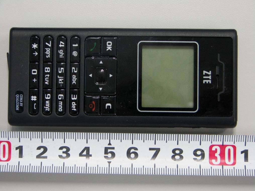
Click to zoom
Application Details
- Equipment Class
- PCE - PCS Licensed Transmitter held to ear
- Date of Grant
- Oct 31, 2008
- Application Purpose
- Original Equipment
- Date of Application
- Oct 31, 2008
- Equipment Note
- CDMA 1X Digital Mobile Phone
- Frequency Range
- 1851.25000000 - 1908.75000000
- Company
- ZTE Corporation
- Country
- China
Documents & Files
Document Text
Text extracted from the exhibit documents filed with the FCC. Open a document above to read the original.
External Photos
ZTE Corporation FCC ID: Q78- ZTEX176 Report No.: ZTEB0809307-24E Page 33 of 36 FCC Part 24E Test Report 13 EXHIBIT C - EUT PHOTOGRAPHS 13.1 EUT Front View 13.2 EUT Rear View
ID Label/Location Info
Internal Use Only ▲ ZTE Corporation Copyright Reserved Abroad Unless Permitted FCC ID Label FCC ID Label Location
Internal Photos
ZTE Corporation FCC ID: Q78- ZTEX176 Report No.: ZTEB0809307-24E Page 34 of 36 FCC Part 24E Test Report 13.3 EUT Rear off View 13.4 EUT Cover off View ZTE Corporation FCC ID: Q78- ZTEX176 Report No.: ZTEB0809307-24E Page 35 of 36 FCC Part 24E Test Report 13.5 EUT Cover off View 13.6 EUT Cover off View ZTE Corporation FCC ID: Q78- ZTEX176 Report No.: ZTEB0809307-24E Page 36 of 36 FCC Part 24E Test Report 13.7 EUT Cover off View 13.8 EUT Power Adapter View ***** End of Report *****
RF Exposure Info
Page 1 of 19 IMMERSIBLE SAR PROBE CALIBRATION REPORT Part Number: IXP – 050 S/N 0201 April 2008 Indexsar Limited Oakfield House Cudworth Lane Newdigate Surrey RH5 5BG Tel: +44 (0) 1306 632 870 Fax: +44 (0) 1306 631 834 e-mail: [email protected] Page 2 of 19 Indexsar Limited Oakfield House Cudworth Lane Newdigate Surrey RH5 5BG Tel: +44 (0) 1306 632 870 Fax: +44 (0) 1306 631 834 e-mail: [email protected] Calibration Certificate 0706/0201 Dosimetric E-field Probe Type: IXP-050 Manufacturer: IndexSAR, UK Serial Number: 0201 Place of Calibration: IndexSAR, UK IndexSAR Limited hereby declares that the IXP-050 Probe named above has been calibrated for conformity to the IEEE 1528 and CENELEC EN 50361 standards on the date shown below. Date of Initial Calibration: 26 nd April 2008 The probe named above will require a calibration check on the date shown below. Next Calibration Date: April 2009 The calibration was carried out using the methods described in the calibration document. Where applicable, the standards used in the calibration process are traceable to the UK’s National Physical Laboratory. Calibrated By: Approved By: Please keep this certificate with the calibration document. When the probe is sent for a calibration check, please include the calibration document. Page 3 of 19 INTRODUCTION This Report presents measured calibration data for a particular Indexsar SAR probe (S/N 0201) and describes the procedures used for characterisation and calibration. Indexsar probes are characterised using procedures that, where applicable, follow the recommendations of CENELEC [1] and IEEE [2] standards. The procedures incorporate techniques for probe linearisation, isotropy assessment and determination of liquid factors (conversion factors). Calibrations are determined by comparing probe readings with analytical computations in canonical test geometries (waveguides) using normalised power inputs. Each step of the calibration procedure and the equipment used is described in the sections below. CALIBRATION PROCEDURE 1. Objectives The calibration process comprises four stages 1) Determination of the channel sensitivity factors which optimise the probe’s overall rotational isotropy in 900MHz brain fluid 2) Determination of the channel sensitivity factors and angular offset of the X channel which together optimise the probe’s spherical isotropy in 900MHz brain fluid 3) Numerical combination of the two sets of channel sensitivity factors to give both acceptable rotational isotropy and acceptable spherical isotropy values 4) At each frequency of interest, application of these channel sensitivity factors to model the exponential decay of SAR in a waveguide fluid cell, and hence derive the liquid conversion factors at that frequency 2. Probe output The probe channel output signals are linearised in the manner set out in Refs [1] and [2]. The following equation is utilized for each channel: U lin = U o/p + U o/p 2 / DCP (1) where U lin is the linearised signal, U o/p is the raw output signal in voltage units and DCP is the diode compression potential in similar voltage units. DCP is determined from fitting equation (1) to measurements of U lin versus source feed power over the full dynamic range of the probe. The DCP is a characteristic of the Schottky diodes used as the sensors. For the IXP-050 probes with CW signals the DCP values are typically 0.10V (or 20 in the voltage units used by Indexsar software, which are V*200). Page 4 of 19 In turn, measurements of E-field are determined using the following equation (where output voltages are also in units of V*200): E liq 2 (V/m) = U linx * Air Factor x * Liq Factor x + U liny * Air Factor y * Liq Factor y + U linz * Air Factor z * Liq Factor z (3) Here, “Air Factor” represents each channel’s sensitivity, while “Liq Factor” represents the enhancement in signal level when the probe is immersed in tissue-simulant liquids at each frequency of interest. 3. Selecting channel sensitivity factors to optimise isotropic response After manufacture, the first stage of the calibration process is to balance the three channels’ Air Factor values, thereby optimising the probe’s overall axial response (“rotational isotropy”). To do this, a 900MHz waveguide containing head-fluid simulant is selected. Like all waveguides used during probe calibration, this particular waveguide contains two distinct sections: an air-filled launcher section, and a liquid cell section, separated by a dielectric matching window designed to minimise reflections at the air-liquid interface. The waveguide stands in an upright position and the liquid cell section is filled with 900MHz brain fluid to within 10 mm of the open end. The depth of liquid ensures there is negligible radiation from the waveguide open top and that the probe calibration is not influenced by reflections from nearby objects. During the measurement, a TE 01 mode is launched into the waveguide by means of an N-type-to-waveguide adapter. The probe is then lowered vertically into the liquid until the tip is exactly 10mm above the centre of the dielectric window. This particular separation ensures that the probe is operating in a part of the waveguide where boundary corrections are not necessary. Care must also be taken that the probe tip is centred while rotating. The exact power applied to the input of the waveguide during this stage of the probe calibration is immaterial since only relative values are of interest while the probe rotates. However, the power must be sufficiently above the noise floor and free from drift. The dedicated Indexsar calibration software rotates the probe in 10 degree steps about its axis, and at each position, an Indexsar ‘Fast’ amplifier samples the probe channels 500 times per second for 0.4 s. The raw U o/p data from each sample are packed into 10 bytes and transmitted back to the PC controller via an optical cable. U linx , U liny and U linz are derived from the raw U o/p values and written to an …
Text truncated - open the document above for the full version.
Test Setup Photos
ZTE Corporation FCC ID: Q78- ZTEX176 Report No.: ZTEB0809307-24E Page 31 of 36 FCC Part 24E Test Report 12 EXHIBIT B - TEST SETUP PHOTOGRAPHS 12.1 Radiated Setup Below 1 GHz Front View Below 1 GHz Rear View ZTE Corporation FCC ID: Q78- ZTEX176 Report No.: ZTEB0809307-24E Page 32 of 36 FCC Part 24E Test Report Above 1 GHz Front View Above 1 GHz Rear View
Contact Information
Applicant
Cary Kong(Product Certification Manager)
Test Firm
Bay Area Compliance Laboratory Corp. (Shenzhen)John Chan
Technical Specifications
| # | Rule Parts | Frequency Range | Power Output | Emission | Tolerance |
|---|---|---|---|---|---|
| 1 | 24E | 1.85 GHz - 1.91 GHz | 164.00 mW | 1M27F9W | 2.5000000000 ppm |
Other Applications from ZTE Corporation

Q78-E1320
Oct 06, 2022Home Gateway
Equipment Class
NII - Unlicensed National Information Infrastructure TX
Q78-E3330
Sep 21, 2022Home Gateway
Equipment Class
JBP - Part 15 Class B Computing Device Peripheral
Q78-ZXV10B866V2
May 23, 2021RichMedia Box
Equipment Class
DTS - Digital Transmission System
Q78-ZXHNH298Q
Apr 22, 2021Home Gateway
Equipment Class
NII - Unlicensed National Information Infrastructure TX
Q78-ZXHNH196Q
Apr 19, 2021Home Gateway
Equipment Class
NII - Unlicensed National Information Infrastructure TX