Q78-ZTEX185CDMA 1X DIGITAL MOBILE PHONE
ZTE Corporation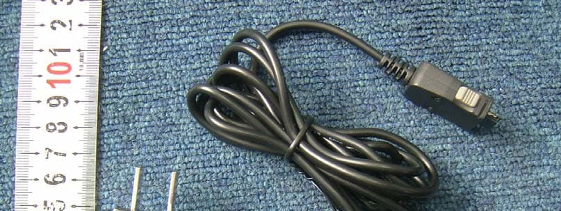
Click to zoom
Application Details
- Equipment Class
- PCE - PCS Licensed Transmitter held to ear
- Date of Grant
- Oct 23, 2006
- Application Purpose
- Original Equipment
- Date of Application
- Oct 22, 2006
- Equipment Note
- CDMA 1X DIGITAL MOBILE PHONE
- Frequency Range
- 1851.25000000 - 1908.75000000
- Company
- ZTE Corporation
- Country
- China
Documents & Files
Document Text
Text extracted from the exhibit documents filed with the FCC. Open a document above to read the original.
Users Manual
ZTEX185 CDMA2000 1X Digital Mobile Phone User Manual 1 Copyright © 2006 by ZTE Corporation All rights reserved. No part of this publication may be excerpted, reproduced, translated or utilized in any form or by any means, electronic or mechanical, including photocopying and microfilm, without the prior written permission of ZTE Corporation. The manual is published by ZTE Corporation. We reserve the right to make modifications on print errors or update specifications without prior notice. Edition: 1 st edition, Sep., 2006 2 Content 1 General Information .............................................................. 8 1.1 Welcome..................................................................................... 8 1.2 Security ...................................................................................... 8 1.3 Safety Warnings .............................................................. 9 1.4 Limit Warranty......................................................................... 13 1.5 Limitation of Liability .............................................................. 14 2 Your Phone .......................................................................... 15 2.1 Instruction of Keypad............................................................... 15 2.2 Instruction of Interface Icon ..................................................... 17 2.3 Technical Parameter ................................................................. 18 2.4 Battery ...................................................................................... 18 2.4.1 Removing and Installation of Battery ................................ 19 2.4.2 Charging the Battery .......................................................... 19 2.5 Connecting to Network ............................................................ 21 2.5.1 UIM Card........................................................................... 21 2.5.2 Insertion and Extraction of UIM card ................................ 22 2.5.3 Power on/off Phone ........................................................... 22 2.5.4 PIN Code ........................................................................... 22 2.5.5 Connecting to Network ...................................................... 23 3 Basic Operation ................................................................... 24 3 3.1 Basic Precondition.................................................................... 24 3.1 Making a Call ........................................................................... 24 3.1.1 Making a Domestic Call .................................................... 25 3.1.2 Making an International Call ............................................. 25 3.1.3 Hand-free ........................................................................... 25 3.1.4 Redialing Recent Calls....................................................... 26 3.2 Answering Calls ....................................................................... 26 3.2.1 Setting Any Key Answer.................................................... 27 3.2.2 Incoming Call Silence........................................................ 27 3.2.3 Silence in Conversation ..................................................... 27 3.2.4 Adjusting Volume in Conversation .................................... 28 3.2.5 Selecting Options in Conversation..................................... 28 3.3 Viewing Missed Calls............................................................... 28 3.4 Menu Functions........................................................................ 28 4 Contacts............................................................................... 30 4.1 Finding Records ....................................................................... 30 4.2 Adding New Record ................................................................. 31 4.3 Viewing Records ...................................................................... 33 4.4 Erasing Records ....................................................................... 34 4.4.1 Erasing a Record................................................................ 34 4.4.2 Erasing All Contacts .......................................................... 34 4.5 Editing Name of the Contacts................................................... 34 4.6 Editing Phone Number ............................................................. 35 4 4.7 Selecting Group........................................................................ 35 4.8 Setting Number Type................................................................ 35 4.9 Setting Speed Dial.................................................................... 36 4.10 Viewing and dialing Speed Dial ............................................. 36 4.11 Memory Status ....................................................................... 37 4.12 Copying All Contacts ............................................................. 37 5 Messages ............................................................................. 39 5.1 Sending a New Message........................................................... 39 5.2 Sending Messages .................................................................... 40 5.3 Receiving Incoming Call while Editing Message..................... 41 5.4 Reading Message ..................................................................... 41 5.5 Viewing OutBox....................................................................... 42 5.6 Erasing Messages ..................................................................... 42 5.6.1 Erasing a Message ............................................................. 43 5.6.2 Erasing All Messages......................................................... 43 5.7 R-UIM...................................................................................... 44 5.8 Sending Preformatted Message ................................................ 45 5.9 Reading Voice Mail ..................…
Text truncated - open the document above for the full version.
Cover Letter(s)
Sep 30, 2006 Federal Communications Commission Authorization and Evaluation Division 7435 Oakland Mills Road Columbia, MD 21046 Confidentiality Request Pursuant to Sections 0.457 and 0.459 of the Commission’s Rules, we, ZTE CORPORATION, hereby request confidential treatment of information accompanying this Application (FCC ID: Q78-ZTEX185) as outlined below: Exhibit Type File Name Block Diagram, ZTE X185 Block Diagram.pdf Schematics ZTE X185 SCH.pdf Operational Description ZTE X185 operational description.pdf Parts List ZTE X185 PART_LIST.pdf Tune Up Info ZTE X185 Tune-up.pdf The above materials contain trade secrets and proprietary information not customarily released to the public. The public disclosure of these matters might be harmful to us, ZTE CORPORATION, and provide unjustified benefits to its competitors. We, ZTE CORPORATION, understand that pursuant to Rule 0.457, disclosure of this Application (FCC ID: Q78-ZTEX185) and all accompanying documentation will not be made before the date of the Grant for this application. Sincerely Yours, LI DEZI ZTE CORPORATION 2006/09/30
Cover Letter(s)
FCC Authorization Date: 2006-09-30 FEDERAL COMMUNICATIONS COMMISSIONS Authorization and Evaluation Division 7435 Oakland Mills Road Columbia, MD 21046 Subject: Agent Authorization To whom it may concern: We ZTE CORPORATION , the undersigned, Hereby authorizes Shanghai Morlab Communication Technology Co.,Ltd to act on its behalf in all matters relating to application for Equipment authorization, including the signing of all documents relating to these matters. All acts carried out by Shanghai Morlab Communication Technology Co.,Ltd on our behalf shall have the same effect as our own action. We, the undersigned, hereby certify that we are not subject to a denial of federal benefits, that includes FCC benefits, pursuant to Section 5301 of the Anti-Drug Abuse Act of 1988, 21 U.S.C. 853(a). This authorization is valid until further written notice from the applicant. Sincerely Yours, Li de zi ZTE CORPORATION 2006/09/30
External Photos
External photos
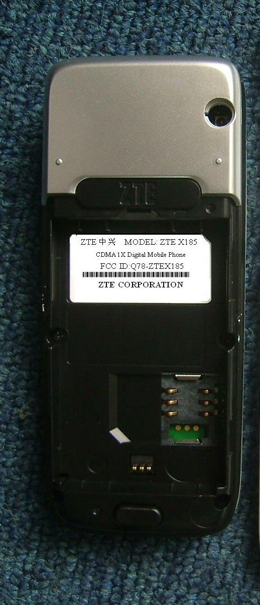
ID Label/Location Info
ZTE中兴 MODEL: ZTE X185 CDMA 1X Digital Mobile Phone FCC ID:Q78-ZTEX185 ZTE CORPORATION ZTE中兴 MODEL: ZTE X185 CDMA 1X Digital Mobile Phone FCC ID:Q78-ZTEX185 ZTE CORPORATION ZTE中兴 MODEL: ZTE X185 CDMA 1X Digital Mobile Phone FCC ID:Q78-ZTEX185 ZTE CORPORATION ZTE中兴 MODEL: ZTE X185 CDMA 1X Digital Mobile Phone FCC ID:Q78-ZTEX185 ZTE CORPORATION
Internal Photos
Internal photos
RF Exposure Info
Report No. SN0112_1900 March 2006 INDEXSAR 1900MHz validation Dipole Type IXD-080 S/N 0112 Performance measurements MI Manning Indexsar, Oakfield House, Cudworth Lane, Newdigate, Surrey RH5 5BG. UK. Tel: +44 (0) 1306 633870 Fax: +44 (0) 1306 631834 e-mail: [email protected] 1. Measurement Conditions Measurements were performed using a box-shaped phantom made of PMMA with dimensions designed to meet the accuracy criteria for reasonably-sized phantoms that do not have liquid capacities substantially in excess of the volume of liquid required to fill the Indexsar upright SAM phantoms used for SAR testing of handsets against the ear. An Anritsu MS4623B vector network analyser was used for the return loss measurements. The dipole was placed in a special holder made of low-permittivity, low-loss materials. This holder enables the dipole to be positioned accurately in the centre of the base of the Indexsar box-phantom used for flat-surface testing and validation checks. The validation dipoles are supplied with special spacers made from a low- permittivity, low-loss foam material. These spacers are fitted to the dipole arms to ensure that, when the dipole is offered up to the phantom surface, the spacing between the dipole and the liquid surface is accurately aligned according to the guidance in the relevant standards documentation. The spacers are rectangular with a central hole equal to the dipole arm diameter and dimensioned so that the longer side can be used to ensure a spacing of 15mm from the liquid in the phantom (for tests at 900MHz and below) and the shorter side can be used for tests at 1800MHz and above to ensure a spacing of 10mm from the liquid in the phantom. The spacers are made on a CNC milling machine with an accuracy of 1/40 th mm but they may suffer wear and tear and need to be replaced periodically. The material used is Rohacell, which has a relative permittivity of approx. 1.05 and a negligible loss tangent. The apparatus supplied by Indexsar for dipole validation tests thus includes: Balanced dipoles for each frequency required are dimensioned according to the guidelines given in IEEE 1528 [1]. The dipoles are made from semi-rigid 50 Ohm co-ax, which is joined by soldering and is gold-plated subsequently. The constructed dipoles are easily deformed, if mis-handled, and periodic checks need to be made of their symmetry. Rohacell foam spacers designed for presenting the dipoles to 2mm thick PMMA box phantoms. These components also suffer wear and tear and should be replaced when the central hole is a loose-fit on the dipole arms or if the edges are too worn to ensure accurate alignment. The standard spacers are dimensioned for use with 2mm wall thickness (additional spacers are available for 4mm wall thickness). 2. Typical SAR Measurement A SAR validation check is performed with the box-phantom located on the SARA2 phantom support base on the SARA2 robot system. Tests are then conducted at a feed power level of approx. 0.25W. The actual power level is recorded and used to normalise the results obtained to the standard input power conditions of 1W (forward power). The ambient temperature is 22 o C +/- 1 o C and the relative humidity is around 40% during the measurements. The phantom is filled with a 1900MHz brain liquid using a recipe from [1], which has the following electrical parameters (measured using an Indexsar DiLine kit) at 1900MHz: Relative Permittivity 41.4 Conductivity 1.85 S/m The SARA2 software version 2.2 VPM is used with an Indexsar probe previously calibrated using waveguides. The 3D measurements made using the dipole at the bottom of the phantom box is shown below: The results, normalised to an input power of 1W (forward power) are typically: Averaged over 1 cm3 (1g) of tissue 4.928 W/kg Averaged over 10cm3 (10g) of tissue 2.362 W/kg These results can be compared with Table 8.1 in [1]. The agreement is within 10%. 3. Dipole impedance and return loss The dipoles are designed to have low return loss ONLY when presented against a lossy-phantom at the specified distance. A Vector Network Analyser (VNA) was used to perform a return loss measurement on the specific dipole when in the measurement-location against the box phantom. The distance was as specified in the standard i.e. 10mm from the liquid (for 1900MHz). The Indexsar foam spacers (described above) were used to ensure this condition during measurement. The impedance was measured at the SMA-connector with the network analyser. The following parameters were measured: Dipole impedance at 1900 MHz Re{Z} = 49.996 Ω Im{Z} = 15.160 mΩ Return loss at 1900MHz -26.175 dB 4. Dipole handling The dipoles are made from standard, copper-sheathed coaxial cable. In assembly, the sections are joined using ordinary soft-soldering. This is necessary to avoid excessive heat input in manufacture, which would destroy the polythene dielectric used for the cable. The consequence of the construction material and the assembly technique is that the dipoles are fragile and can be deformed by rough handling. Conversely, they can be straightened quite easily as described in this report. If a dipole is suspected of being deformed, a normal workshop lathe can be used as an alignment jig to restore the symmetry. To do this, the dipole is first placed in the headstock of the lathe (centred on the plastic or brass spacers) and the headstock is rotated by hand (do NOT use the motor). A marker (lathe tool or similar) is brought up close to the end of one dipole arm and then the headstock is rotated by 0.5 rev. to check the opposing arm. If they are not balanced, judicious deformation of the arms can be used to restore the symmetry. If a dipole has a failed solder joint, the dipole can be fixed down in such a way that the arms are co-linear and the joint re-soldered with a reasonably-powerful electrical soldering iron. Do not use gas soldering irons. After such a repair, electrical tests must be performed as described below. Please note th…
Text truncated - open the document above for the full version.
RF Exposure Info
IMMERSIBLE SAR PROBE CALIBRATION REPORT Part Number: IXP – 050 S/N 0177 March 2006 Indexsar Limited Oakfield House Cudworth Lane Newdigate Surrey RH5 5BG Tel: +44 (0) 1306 632 870 Fax: +44 (0) 1306 631 834 e-mail: [email protected] Page 1 of 19 Page 2 of 19 INTRODUCTION This Report presents measured calibration data for a particular Indexsar SAR probe (S/N 0177) and describes the procedures used for characterisation and calibration. Indexsar probes are characterised using procedures that, where applicable, follow the recommendations of CENELEC [1] and IEEE [2] standards. The procedures incorporate techniques for probe linearisation, isotropy assessment and determination of liquid factors (conversion factors). Calibrations are determined by comparing probe readings with analytical computations in canonical test geometries (waveguides) using normalised power inputs. Each step of the calibration procedure and the equipment used is described in the sections below. CALIBRATION PROCEDURE 1. Objectives The calibration process comprises three stages 1) Determination of the channel sensitivity factors which optimise the probe’s overall rotational isotropy in 1800MHz brain fluid 2) At each frequency of interest, application of these channel sensitivity factors to model the exponential decay of SAR in a waveguide fluid cell, and hence derive the liquid conversion factors at that frequency 3) Determination of the effective tip radius and angular offset of the X channel which together optimise the probe’s spherical isotropy in 900MHz brain fluid 2. Probe output The probe channel output signals are linearised in the manner set out in Refs [1] and [2]. The following equation is utilized for each channel: U lin = U o/p + U o/p 2 / DCP (1) where U lin is the linearised signal, U o/p is the raw output signal in voltage units and DCP is the diode compression potential in similar voltage units. DCP is determined from fitting equation (1) to measurements of U lin versus source feed power over the full dynamic range of the probe. The DCP is a characteristic of the Schottky diodes used as the sensors. For the IXP-050 probes with CW signals the DCP values are typically 0.10V (or 20 in the voltage units used by Indexsar software, which are V*200). In turn, measurements of E-field are determined using the following equation (where output voltages are also in units of V*200): Page 3 of 19 E liq 2 (V/m) = U linx * Air Factor x * Liq Factor x + U liny * Air Factor y * Liq Factor y + U linz * Air Factor z * Liq Factor z (3) Here, “Air Factor” represents each channel’s sensitivity, while “Liq Factor” represents the enhancement in signal level when the probe is immersed in tissue-simulant liquids at each frequency of interest. 3. Selecting channel sensitivity factors to optimise isotropic response After manufacture, the first stage of the calibration process is to balance the three channels’ Air Factor values, thereby optimising the probe’s overall axial response (“rotational isotropy”). To do this, an 1800MHz waveguide containing head-fluid simulant is selected. Like all waveguides used during probe calibration, this particular waveguide contains two distinct sections: an air-filled launcher section, and a liquid cell section, separated by a dielectric matching window designed to minimise reflections at the air-liquid interface. The waveguide stands in an upright position and the liquid cell section is filled with 1800MHz brain fluid to within 10 mm of the open end. The depth of liquid ensures there is negligible radiation from the waveguide open top and that the probe calibration is not influenced by reflections from nearby objects. During the measurement, a TE 01 mode is launched into the waveguide by means of an N-type-to-waveguide adapter. The probe is then lowered vertically into the liquid until the tip is exactly 10mm above the centre of the dielectric window. This particular separation ensures that the probe is operating in a part of the waveguide where boundary corrections are not necessary. Care must also be taken that the probe tip is centred while rotating. The exact power applied to the input of the waveguide during this stage of the probe calibration is immaterial since only relative values are of interest while the probe rotates. However, the power must be sufficiently above the noise floor and free from drift. The dedicated Indexsar calibration software rotates the probe in 10 degree steps about its axis, and at each position, an Indexsar ‘Fast’ amplifier samples the probe channels 500 times per second for 0.4 s. The raw U o/p data from each sample are packed into 10 bytes and transmitted back to the PC controller via an optical cable. U linx , U liny and U linz are derived from the raw U o/p values and written to an Excel template. Once data have been collected from a full probe rotation, the Air Factors are adjusted using a special Excel Solver routine to equalise the output from each channel and hence minimise the rotational isotropy. This automated approach to optimisation removes the effect of human bias. Figure 5 represents the output from each diode sensor as a function of probe rotation angle. The directionality of the orthogonally-arranged sensors can be checked by analysing the data using dedicated Indexsar software, which displays the data in 3D format, a representative image of which is shown in Figure 3. The left-hand side of this diagram shows the individual channel outputs after linearisation (see above). The program uses these data to balance the channel outputs and then applies an optimisation process, which makes fine adjustments to the channel factors for optimum isotropic response. 4. Determination of Conversion (“Liquid”) Factors at each frequency of interest A lookup table of conversion factors for a probe allows a SAR value to be derived at the measured frequencies, and for either brain or body fluid- simulant. The method by which the conversion factors are assessed is based…
Text truncated - open the document above for the full version.
RF Exposure Info
No.SAR06-054 Page 3 of 50 Contents 1. GENERAL CONDITIONS 2. ADMINISTRATIVE DATA 2.1. Identification of the Responsible Testing Laboratory 2.2. Identification of the Responsible Testing Location(s) 2.3. Organization Item 2.4. Identification of Applicant 2.5. Identification of Manufacture 3. EQUIPMENT UNDER TEST (EUT) 3.1. Identification of the Equipment under Test 3.2. Identification of all used Test Sample of the Equipment under Test 4. OPERATIONAL CONDITIONS DURING TEST 4.1. Schematic Test Configuration 4.2. SAR Measurement System 5. CHARACTERISTICS OF THE TEST 5.1. Applicable Limit Regulations 5.2. Applicable Measurement Standards 6. LABORATORY ENVIRONMENT 7. TEST RESULTS 7.1. Dielectric Performance 7.2. Summary of Measurement Results 7.3. Conclusion 8. MEASUREMENT UNCERTAINTY 9. MAIN TEST INSTRUMENTS This Test Report consists of the following Annexes: Annex A: Accreditation Certificate Annex B: Test Layout Annex C: Sample Photographs Annex D: Graph Test Results Annex E: System Performance Check Data No.SAR06-054 Page 4 of 50 1GENERAL CONDITIONS 1.1 This report only refers to the item that has undergone the test. 1.2 This report standalone dose not constitute or imply by its own an approval of the product by the certification Bodies or competent Authorities. 1.3 This document is only valid if complete; no partial reproduction can be made without written approval of Shenzhen Electronic Product Quality Testing Center. 1.4 This report cannot be used partially or in full for publicity and/or promotional purposes without previous written approval of Shenzhen Electronic Product Quality Testing Center and the Accreditation Bodies, if it applies. No. SAR06-054 Page 5 of 50 2. Administrative Date 2.1. Identification of the Responsible Testing Laboratory Company Name: ShenZhen Electronic Product Quality Testing Center Department: Testing Department Address: Electronic Testing Building, ShaHe Road, NanShan District, ShenZhen, P. R. China Telephone: +86-755-26628676 Fax: +86-755-26627238 Responsible Test Lab Managers: Mr. Wu Li’an 2.2. Identification of the Responsible Testing Location(s) Company Name: ShenZhen Electronic Product Quality Testing Center Address: Electronic Testing Building, ShaHe Road, NanShan District, ShenZhen, P. R. China 2.3. Organization Item S.E.T Report No.: SAR06-054 S.E.T Project Leader: Mr. Li Sixiong S.E.T Responsible for accreditation scope: Mr. Wu Li’an Start of Testing: 2006-10-15 End of Testing: 2006-10-17 2.4. Identification of Applicant Company Name: ZTE Corporation Address: Zhongxing Bldg, Hi-Tech Park, NanShan, ShenZhen, P.R.China Contact person: Li dezi Telephone: +86-21-68895196 Fax: +86-21-50801070 2.5. Identification of Manufacture Company Name: ZTE Corporation Address: Zhongxing Bldg, Hi-Tech Park, NanShan, ShenZhen, P.R.China Contact person: Li dezi Telephone: +86-21-68895196 Fax: +86-21-50801070 Notes: This data is based on the information by the applicant. No. SAR06-054 Page 6 of 50 3. Equipment Under Test (EUT) 3.1. Identification of the Equipment under Test Brand Name: ZTE Type Name: ZTE X185 Marking Name: ZTE X185 Test frequency CDMA 1900MHz Development Stage Identical Prototype Accessories Charger Battery type Li3708T42p3h553762 Battery specification800mAh 3.7V Antenna type Build inside Operation mode Call established Modulation mode CDMA 1X General description: Max. Power(ERP) 0.266W (24.25dBm) NOTE: 1. The EUT consists of Hand Telephone Set and normal options: Lithium Battery , as listed above. 2. Please refer to Appendix C for the photographs of the EUT. For a more detailed features description about the EUT, please refer to User’s Manual. 3.2. Identification of all used Test Sample of the Equipment under Test EUT Code ESN Hardware Version Software Version MIN 1# 2F 6667C0 cg1B CH_X185V1.0.1B03 460030980321414 No. SAR06-054 Page 7 of 50 4 OPERATIONAL CONDITIONS DURING TEST 4.1 Schematic Test Configuration During SAR test, EUT is in Traffic Mode (Channel Allocated) at Normal Voltage Condition. A communication link is set up with a System Simulator (SS) by air link, and a call is established. The TCH is allocated to 25, 600 and 1175 respectively in the case of CDMA 1900 MHz. The EUT is commanded to operate at maximum transmitting power. The EUT shall use its internal transmitter. The antenna(s), battery and accessories shall be those specified by the manufacturer. The EUT battery must be fully charged and checked periodically during the test to ascertain uniform power output. If a wireless link is used, the antenna connected to the output of the base station simulator shall be placed at least 50 cm away from the handset. The signal transmitted by the simulator to the antenna feeding point shall be lower than the output power level of the handset by at least 35 dB. 4.2 SAR Measurement System The SAR measurement system being used is the IndexSAR SARA2 system, which consists of a Figure1. SAR Lab Test Measurement Set-up Mitsubishi RV-E2 6-axis robot arm and controller, IndexSAR probe and amplifier and SAM phantom No. SAR06-054 Page 8 of 50 Head Shape. The system is controlled remotely from a PC, which contains the software to control the robot and data acquisition equipment. The software also displays the data obtained from test scans. In operation, the system first does an area (2D) scan at a fixed depth within the liquid from the inside wall of the phantom. When the maximum SAR point has been found, the system will then carry out a 3D scan centred at that point to determine volume averaged SAR level. 4.2.1 Robot system specification The robot is used to articulate the probe to programmed positions inside the phantom head to obtain the SAR readings from the DUT. 4.2.2 Probe and amplifier specification IXP-050 Indexsar isotropic immersible SAR probe The probes are constructed using three orthogonal dipole sensors arranged on an interlocking, triangular prism core. The probes have built-in shielding against static charges and are contained within a PEEK …
Text truncated - open the document above for the full version.
Test Report
Report No. FCC06-8074 Page 2 of 49 Table of Contents 1 Test Report Certification ...............................................................................................................5 2 General Information ......................................................................................................................6 2.1 Description of EUT ...............................................................................................................6 2.2 Objective ...............................................................................................................................7 2.3 Test Standards and Results ....................................................................................................7 2.4 List of Equipments Used .......................................................................................................8 2.5 Test Facility ...........................................................................................................................8 2.6 Environmental conditions .....................................................................................................8 3 Conducted Emission Test ..............................................................................................................9 3.1 Limits of Conducted Emission..............................................................................................9 3.2 Test Procedure .......................................................................................................................9 3.3 Test Setup ............................................................................................................................10 3.4 EUT Setup and Operating Conditions.................................................................................10 3.5 Test Results .........................................................................................................................10 4 Radiated Emission Test ...............................................................................................................12 4.1 Limits of Radiated Emission ...............................................................................................12 4.2 Test Procedure .....................................................................................................................12 4.3 Test Setup ............................................................................................................................13 4.4 EUT Setup and Operating Conditions.................................................................................13 4.5 Test Results .........................................................................................................................13 5 Frequencies .................................................................................................................................15 5.1 Frequency Blocks Available for Broadband PCS ...............................................................15 5.2 Test Procedure .....................................................................................................................15 5.3 Test Setup ............................................................................................................................16 5.4 EUT Setup and Operating Conditions.................................................................................16 5.6 Test Results .........................................................................................................................16 6 Conducted RF Output …
Text truncated - open the document above for the full version.
Contact Information
Applicant
Cary Kong(Product Certification Manager)
Test Firm
ShenZhen Electronic Product Quality Testing CenterXingsun Lin
Technical Specifications
| # | Rule Parts | Frequency Range | Power Output | Emission | Tolerance |
|---|---|---|---|---|---|
| 1 | 24E | 1.85 GHz - 1.91 GHz | 266.00 mW | 1M25F9W | 150.0000000000 Hz |
Other Applications from ZTE Corporation

Q78-E1320
Oct 06, 2022Home Gateway
Equipment Class
NII - Unlicensed National Information Infrastructure TX
Q78-E3330
Sep 21, 2022Home Gateway
Equipment Class
JBP - Part 15 Class B Computing Device Peripheral
Q78-ZXV10B866V2
May 23, 2021RichMedia Box
Equipment Class
DTS - Digital Transmission System
Q78-ZXHNH298Q
Apr 22, 2021Home Gateway
Equipment Class
NII - Unlicensed National Information Infrastructure TX
Q78-ZXHNH196Q
Apr 19, 2021Home Gateway
Equipment Class
NII - Unlicensed National Information Infrastructure TX