Q78ZXR10W800AWireless Access Point
ZTE Corporation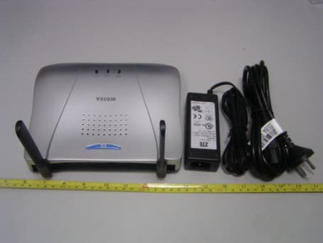
Click to zoom
Application Details
- Equipment Class
- DTS - Digital Transmission System
- Date of Grant
- Jul 16, 2004
- Application Purpose
- Original Equipment
- Date of Application
- Jul 16, 2004
- Equipment Note
- Wireless Access Point
- Frequency Range
- 2412.00000000 - 2462.00000000
- Company
- ZTE Corporation
- Country
- China
Documents & Files
Document Text
Text extracted from the exhibit documents filed with the FCC. Open a document above to read the original.
Users Manual
ZXR10 WAS (V2.0) IP Wireless Access System W800A Wireless Access Point User’s Manual ZTE CORPORATION ZXR10 WAS (V2.0) IP Wireless Access System W800A Wireless Access Point User’s Manual Manual Version 20040306-R1.0 Product Version V2.0 BOM ×××××××× Copyright © 2003 ZTE Corporation All rights reserved. No part of this documentation may be excerpted, reproduced, translated, annotated or duplicated, in any form or by any means without the prior written permission of ZTE Corporation. ZTE CORPORATION ZTE Plaza, Keji Road South, Hi-Tech Industrial Park, Nanshan District, Shenzhen, P. R. China Website: http://www.zte.com.cn Post code: 518057 Customer Support Center: (+86755) 26770800 800-830-1118 Fax: (+86755) 26770801 E-mail: [email protected] * * * * S.N.: DDDDDDDDD FAX: +86-755-26770160 Suggestions and Feedback To improve the quality of ZTE product documentation and offer better services to our customers, we hope you can give us your suggestions and comments on our documentation and fax this form to 0086-755-26770160; or mail to “ZTE Plaza, Keji Road South, Hi-Tech Industrial Park, Nanshan District, Shenzhen, P. R. China”. Our postcode is 518057. Document Name ZXR10 WAS (V2.0) IP Wireless Access System W800A Wireless Access Point User’s Manual Product version V2.0 Document version 20040306-R1.0 Equipment installation time Your information Name Company Postcode Company address Telephone E-mail Good Fair Average Poor Bad Overall Instructiveness Index Correctness Completeness Structure Illustration Your evaluation of this documentation Readability Overall Instructiveness Index Correctness Completeness Structure Illustration Your suggestion on the improvement of this documentation Readability Your other suggestions on ZTE product documentation Preface About This Manual This manual, ZXR10 WAS (V2.0) IP Wireless Access System W800A Wireless Access Point — User’s Manual, is applicable to W800A wireless access point (W800A for short) of the ZXR10 WAS (V2.0) IP wireless access system. The ZXR10 WAS IP wireless access system is the IP wireless access system developed by ZTE. It consists of a series of wireless access network products, such as wireless network card, wireless access point (AP) and DSL 2-in-1 wireless router. Serving as the operation guide to W800A, this manual introduces the function features, installation, operation, using and maintenance of W800A. This manual consists of 7 chapters and 2 appendixes. Chapter 1, Safety Precautions, introduces the safety precautions of this product and safety symbols used in this manual. Chapter 2, Overview, presents functions, features and technical parameters of W800A. Chapter 3, Structure and Principle, describes structure and principle of W800A. Chapter 4, Installation and Debugging, deals with the installation and debugging methods of W800A. Chapter 5, Command Line Configuration, covers the command line configurations of W800A. Chapter 6, WEB Configuration, examines WEB configurations of W800A. Chapter 7, Maintenance, puts forward the daily maintenance and version upgrade methods of W800A. Appendix A, Packing, Transportation and Storage, outlines the packaging method, storage conditions and transportation precautions of W800A. Appendix B, Making of Ethernet cables, details the power supply mode of W800A Ethernet and making of Ethernet cables. Conventions Four striking symbols are used throughout this manual to emphasize important and critical information during operation: Attention, Caution, Warning and Danger: alerting you to pay attention to something. Statement: The actual product may differ from what is described in this manual due to frequent update of ZTE products and fast development of technologies. Please contact the local ZTE office for the latest updating information of the product. -i- Contents 1 Safety Precautions...................................................................................................................1-1 1.1 Safety Precautions............................................................................................................1-1 1.2 Symbol Description...........................................................................................................1-2 2 Overview................................................................................................................................2-1 2.1 Preface............................................................................................................................2-1 2.2 Functions and Features......................................................................................................2-1 2.3 Technical Characteristics and Parameters.............................................................................2-3 3 Structure and Principle...........................................................................................................3-1 3.1 Structure and Working Principle.........................................................................................3-1 3.2 Units/Components............................................................................................................3-2 3.2.1 Front Panel...............................................................................................................3-2 3.2.2 Rear Control Panel....................................................................................................3-3 3.3 Networking Modes...........................................................................................................3-4 3.3.1 AP Mode Application................................................................................................3-5 3.3.2 Bridge Connection Mode Application..........................................................................3-6 3.3.3 Wireless Repeater Mode Application...........................................................................3-7 4 Installation and Debugging...................................................................…
Text truncated - open the document above for the full version.
Users Manual
ZXR10 WAS (V2.0) IP Wireless Access System W800A Wireless Access Point Professional Installation Instruction Manual ZTE CORPORATION ZXR10 WAS (V2.0) IP Wireless Access System W800A Wireless Access Point Professional Installation Instruction Manual Manual Version 20040306-R1.0 Product Version V2.0 BOM ×××××××× Copyright © 2003 ZTE Corporation All rights reserved. No part of this documentation may be excerpted, reproduced, translated, annotated or duplicated, in any form or by any means without the prior written permission of ZTE Corporation. ZTE CORPORATION ZTE Plaza, Keji Road South, Hi-Tech Industrial Park, Nanshan District, Shenzhen, P. R. China Website: http://www.zte.com.cn Post code: 518057 Customer Support Center: (+86755) 26770800 800-830-1118 Fax: (+86755) 26770801 E-mail: [email protected] * * * * S.N.: DDDDDDDDD FAX: +86-755-26770160 Suggestions and Feedback To improve the quality of ZTE product documentation and offer better services to our customers, we hope you can give us your suggestions and comments on our documentation and fax this form to 0086-755-26770160; or mail to “ZTE Plaza, Keji Road South, Hi-Tech Industrial Park, Nanshan District, Shenzhen, P. R. China”. Our postcode is 518057. Document Name ZXR10 WAS (V2.0) IP Wireless Access System W800A Wireless Access Point User’s Manual Product version V2.0 Document version 20040306-R1.0 Equipment installation time Your information Name Company Postcode Company address Telephone E-mail Good Fair Average Poor Bad Overall Instructiveness Index Correctness Completeness Structure Illustration Your evaluation of this documentation Readability Overall Instructiveness Index Correctness Completeness Structure Illustration Your suggestion on the improvement of this documentation Readability Your other suggestions on ZTE product documentation Preface About This Manual This manual, ZXR10 WAS (V2.0) IP Wireless Access System W800A Wireless Access Point — User’s Manual, is applicable to W800A wireless access point (W800A for short) of the ZXR10 WAS (V2.0) IP wireless access system. The ZXR10 WAS IP wireless access system is the IP wireless access system developed by ZTE. It consists of a series of wireless access network products, such as wireless network card, wireless access point (AP) and DSL 2-in-1 wireless router. Serving as the operation guide to W800A, this manual introduces the function features, installation, operation, using and maintenance of W800A. This manual consists of 7 chapters and 2 appendixes. Chapter 1, Safety Precautions, introduces the safety precautions of this product and safety symbols used in this manual. Chapter 2, Installation and Debugging, deals with the installation and debugging methods of W800A. Chapter 3, Command Line Configuration, covers the command line configurations of W800A. Appendix B, Making of Ethernet cables, details the power supply mode of W800A Ethernet and making of Ethernet cables. Conventions Four striking symbols are used throughout this manual to emphasize important and critical information during operation: Attention, Caution, Warning and Danger: alerting you to pay attention to something. Statement: The actual product may differ from what is described in this manual due to frequent update of ZTE products and fast development of technologies. Please contact the local ZTE office for the latest updating information of the product. Warning This instruction manual only apply to W800A with the following antennas: TQJ-5800BKF40-W, TQJ-5800C-5, TQJ-5800BKF8, R0322-025 -i- Contents 1 Safety Precautions...................................................................................................................1-1 1.1 Safety Precautions.............................................................................................................1-1 1.2 Symbol Description...........................................................................................................1-2 2 Installation and Debugging.......................................................................................................2-1 2.1 Installation Preparations.....................................................................................................2-1 2.1.1 Installation Preparation Flow.......................................................................................2-1 2.1.2 Tool, Instrument and Document...................................................................................2-3 2.1.3 Installation Environment Inspection.............................................................................2-4 2.1.4 Unpacking Inspection.................................................................................................2-4 2.2 Installation........................................................................................................................2-4 2.3 Power-on and Power-off.....................................................................................................2-6 2.4 Debugging........................................................................................................................2-6 3 Command Line Configuration..................................................................................................3-1 3.1 Overview..........................................................................................................................3-1 3.2 User Mode........................................................................................................................3-4 3.2.1 Entering the Privileged Mode......................................................................................3-4 3.2.2 Exiting the Telnet Configuration..................................................................................3-4 3.3 Privileged Mode................................................................................................................3-5 3.3.1 Network Connectivity Check............................................................…
Text truncated - open the document above for the full version.
Block Diagram
W800A Microprocessor ethernet phy 802.11a/b/g wireless card X'TAL 25MHz X'TAL 33MHz sdramflashboot RS232 transceiver V power circuit transformer RJ45 RJ11 48v input logic circuit reset circuit i/o bus run led act led wachdog power led ac t led 10M led 100M LED DATA BUS ADDR BUS mii 12v input 3.3v output LDO LDO LDO 1.25V output 2.5V output 1.3V output DATA BUS ADDR BUS 802.11g wireless card PCI BUS driver antenna antenna frequence: 2.4~2.4835G/5.15~5.25G/ 5.25~5.35G/5.725~5.825GHZ (vary by coutry) frequence: 2.4G~2.4835GHZ
Cover Letter(s)
ZTE Corporation Federal Communications Commission Authorization and Evaluation Division Confidentiality Request regarding application for certification of FCC ID: Q78-ZXR10W800A Pursuant to Sections 0.457 and 0.459 of the Commission’s Rules, we hereby request confidential treatment of information accompanying this application as outlined below: (1)Schematics (2)Part lists (3)Layouts The above materials contain trade secrets and proprietary information not customarily released to the public. The public disclosure of these materials may be harmful to the applicant and provide unjustified benefits to its competitors. The applicant understands that pursuant to Section 0.457 of the Rules, disclosure of this application and all accompanying documentation will not be made before the date of the Grant for this application. Sincerely, (signature) (printed name): Wang Zhenying
External Photos
EXHIBIT C - EUT EXTERNAL PHOTOGRAPHS EUT with Antenna View 1, Model: TWM-614 EUT with Antenna View 2, Model: TWM-614 EUT with Antenna View 3, Model: TWM-614 EUT with Antenna View 4, Model: TWM-614 EUT – View (5) Antenna – R0322-025 View (1) Antenna – R0322-025 View (2) Antenna – TQJ-5800BKF8 View (1) Antenna –TQJ-5800BKF8 View (2) Antenna – TQJ-5800C-5 View (1) Antenna –TQJ-5800C-5 View (2) Antenna – TQJ-5800BKC40-W View (1) Antenna –TQJ-5800BKC40-W View (2)
ID Label/Location Info
EXHIBIT A - FCC ID LABEL INFORMATION Proposed FCC ID Label Proposed Label Location on Notebook Proposed Label Location FCC ID: Q78ZXR10W800A This device complies with Part 15 o the FCC Rules. Operation is subject to the following two conditions: (1) this device may not cause harmful interference, and (2) this device must accept any interference received, including interference that may cause undesired operation. 2.1875" 1.0" Label H
Internal Photos
EXHIBIT C - EUT INTERNAL PHOTOGRAPHS EUT Cover Off with Antenna View 1, Model: TWM-614 EUT Cover Off with Antenna View 2, Model: TWM-614 EUT Cover Off with Antenna View 3, Model: TWM-614 EUT Cover Off with Antenna View 4, Model: TWM-614 EUT – Cover off View EUT – Main Board Front View EUT – Main Board Back View LAN Card – Front View LAN Card – Back View LAN Card – Uncovered View LAN Card View
Operational Description
Circuit Description 1. Data transmission from wired to wireless 1) The user is connected to X5 via wireless Data packets are transmitted to Ethernet PHY D5 (L80223) via X9 (RJ45) interface and then transmitted to D1 (IDT79RC32K438) via MII interface. After the processing of CPU, data are transmitted to wireless network card X5 (WMIA105AG) via PCI interface. Signals will then be transmitted via the antenna on the wireless network card after the processing of the card. 2) The user is connected to X6 via wireless Data packets are transmitted to Ethernet PHY D5 (L80223) via X9 (RJ45) interface and then transmitted to D1 (IDT79RC32K438) via MII interface. After the processing of CPU, data are transmitted to wireless network card X6 (WN4402A) via PCI interface. Signals will then be transmitted via the antenna on the wireless network card after the processing of the card. 2. Data retransmission from wireless to wired 1) The user is connected to X5 via wireless The wireless network card (WMIA105AG) processes packet signals received via the antenna and sends them to D1 (IDT79RC32K438) via X5 PCI interface. After the processing of CPU, signals will be transmitted to Ethernet PHY D5 (L80223) via MII interface. Ethernet packets will then be sent out via X9 (RJ45) interface. 2) The user is connected to X6 via wireless The wireless network card (WN4402A) processes packet signals received via the antenna and sends them to D1 (IDT79RC32K438) via X5 PCI interface. After the processing of CPU, signals will be transmitted to Ethernet PHY D5 (L80223) via MII interface. Ethernet packets will then be sent out via X9 (RJ45) interface. 3. Converting 48V to 3.3V An external power supply provides the card with 48V power via X9 (RJ45). Passing through commutation diode VD3-VD6 (IN4007), lightning protection circuit D11-12 (SCK08102), VD8-9 (SMCJ58AT3), filter circuit and then L2, L3 (DO3316P-272HC), the current will enter the DC-DC converting circuit. In the DC-DC circuit, D10 (TPS60061) generates PWM chopping signals to control the VT3 (FDD3630) and VT4 (SI9407) switches of the MOS tube. After passing through L1 (DO5022P 103H), the 3.3V current will be output. 4. Converting 12V to 3.3V An external 12V DC power supply provides the card with 12V power via X4 (DC-470). After capacitor filtering, the current enters the DC-DC converting circuit directly. The 12V and 48V power supplies share the same DC-DC converting circuit. 5. Converting 3.3V to 2.5V The 3.3V power is converted directly to 2.5V via LDO D16 (MIC39300). 6. Converting 3.3V to 1.3V The 3.3V power is converted directly to 1.3V via LDO D15 (SPX1585). 7. Converting 2.5V to 1.25V The 2.5V power is converted directly to 1.25V via DDR voltage regulator D14 (LP2995).
Test Report
Note: This test report is specially limited to the above client company and product model only. It may not be duplicated without prior written consent of Bay Area Compliance Laboratory Corporation. This report must not be used by the client to claim product endorsement by NVLAP or any agency of the U.S. Government. FCC PART 15.247 & 15.407 EMI MEASUREMENT AND TEST REPORT For ZTE Corporation ZTE Plaza, Hi-Tech Industrial Park, Shenzhen, P. R. China FCC ID: Q78ZXR10W800A 2004-05-03 This Report Concerns: Original Report Equipment Type: W800A Wireless Access Point Test Engineer: Jandy Su Report No.: RSH04031611 Test Date: 2004-04-2 / 2004-04-09 Reviewed By: Chris Zeng Prepared By: Bay Area Compliance Lab Corp. ShenZhen Suite C, 41-D Electronics Science & Technology Building, No. 2070 Shennanzhong Rd ShenZhen, Guandong 518031, P.R. China Tel: (755) 83296449 Fax: (755) 8327375 ZTE Corporation FCC ID: Q78ZXR10W800A Report # RSH04031611Rpt_rev1 Page 2 of 122 FCC Part 15.247 & 15.407 Test Report TABLE OF CONTENTS GENERAL INFORMATION......................................................................................................................................................4 PRODUCT DESCRIPTION FOR EQUIPMENT UNDER TEST (EUT)...............................................................................................4 OBJECTIVE.......................................................................................................................................................................................4 RELATED SUBMITTAL(S)/GRANT(S)............................................................................................................................................4 TEST METHODOLOGY....................................................................................................................................................................4 TEST FACILITY................................................................................................................................................................................4 HOST SYSTEM CONFIGURATION LIST AND DETAILS.................................................................................................................5 LOCAL SUPPORT EQUIPMENT LIST AND DETAILS.....................................................................................................................5 EXTERNAL I/O CABLE...................................................................................................................................................................5 SYSTEM TEST CONFIGURATION........................................................................................................................................6 JUSTIFICATION................................................................................................................................................................................6 EUT EXERCISE SOFTWARE...........................................................................................................................................................6 SPECIAL ACCESSORIES..................................................................................................................................................................6 SCHEMATICS / BLOCK DIAGRAM.................................................................................................................................................6 EQUIPMENT MODIFICATIONS........................................................................................................................................................6 CONFIGURATION OF EUT..............................................................................................................................................................6 TEST SETUP BLOCK DIAGRAM.....................................................................................................................................................7 SUMMARY OF TEST RESULTS..............................................................................................................................................8 §15.207(A) - CONDUCTED EMISSIONS................................................................................................................................9 MEASUREMENT UNCERTAINTY....................................................................................................................................................9 EUT SETUP......................................................................................................................................................................................9 SPECTRUM ANALYZER SETUP....................................................................................................................................................10 TEST EQUIPMENT LIST AND DETAILS........................................................................................................................................10 TEST PROCEDURE.........................................................................................................................................................................10 TEST DATA....................................................................................................................................................................................11 TEST RESULT: PASS.....................................................................................................................................................................11 PLOT(S) OF TEST DATA................................................................................................................................................................11 §15.209(A) - ANTENNA PORT CONDUCTED SPURIOUS EMISSION TEST (30M-40G)..................................13 STANDARD APPLICABLE................................................................................................…
Text truncated - open the document above for the full version.
Test Report
ZTE Corporation FCC ID: Q78ZXR10W800A Report # RSH04031611Rpt_rev1 Page 31 of 122 FCC Part 15.247 & 15.407 Test Report (5.15GHz-5.25GHz) High Channel BPSK 802.11a ZTE Corporation FCC ID: Q78ZXR10W800A Report # RSH04031611Rpt_rev1 Page 32 of 122 FCC Part 15.247 & 15.407 Test Report ZTE Corporation FCC ID: Q78ZXR10W800A Report # RSH04031611Rpt_rev1 Page 33 of 122 FCC Part 15.247 & 15.407 Test Report (5. 25GHz-5.35GHz) Low Channel BPSK 802.11a ZTE Corporation FCC ID: Q78ZXR10W800A Report # RSH04031611Rpt_rev1 Page 34 of 122 FCC Part 15.247 & 15.407 Test Report ZTE Corporation FCC ID: Q78ZXR10W800A Report # RSH04031611Rpt_rev1 Page 35 of 122 FCC Part 15.247 & 15.407 Test Report (5. 25GHz-5.35GHz) Middle Channel BPSK 802.11a ZTE Corporation FCC ID: Q78ZXR10W800A Report # RSH04031611Rpt_rev1 Page 36 of 122 FCC Part 15.247 & 15.407 Test Report ZTE Corporation FCC ID: Q78ZXR10W800A Report # RSH04031611Rpt_rev1 Page 37 of 122 FCC Part 15.247 & 15.407 Test Report (5. 25GHz-5.35GHz) High Channel BPSK 802.11a ZTE Corporation FCC ID: Q78ZXR10W800A Report # RSH04031611Rpt_rev1 Page 38 of 122 FCC Part 15.247 & 15.407 Test Report ZTE Corporation FCC ID: Q78ZXR10W800A Report # RSH04031611Rpt_rev1 Page 39 of 122 FCC Part 15.247 & 15.407 Test Report (5.725GHz-5.825GHz) Low Channel BPSK 802.11a ZTE Corporation FCC ID: Q78ZXR10W800A Report # RSH04031611Rpt_rev1 Page 40 of 122 FCC Part 15.247 & 15.407 Test Report ZTE Corporation FCC ID: Q78ZXR10W800A Report # RSH04031611Rpt_rev1 Page 41 of 122 FCC Part 15.247 & 15.407 Test Report (5.725GHz-5.825GHz) Middle Channel BPSK 802.11a ZTE Corporation FCC ID: Q78ZXR10W800A Report # RSH04031611Rpt_rev1 Page 42 of 122 FCC Part 15.247 & 15.407 Test Report ZTE Corporation FCC ID: Q78ZXR10W800A Report # RSH04031611Rpt_rev1 Page 43 of 122 FCC Part 15.247 & 15.407 Test Report (5.725GHz-5.825GHz) High Channel BPSK 802.11a ZTE Corporation FCC ID: Q78ZXR10W800A Report # RSH04031611Rpt_rev1 Page 44 of 122 FCC Part 15.247 & 15.407 Test Report ZTE Corporation FCC ID: Q78ZXR10W800A Report # RSH04031611Rpt_rev1 Page 45 of 122 FCC Part 15.247 & 15.407 Test Report §15.247(b)(3), §15.407(a)(2) - PEAK OUTPUT POWER MEASUREMENT Standard Applicable According to §15.247(b) (3), for systems using digital modulation in 2400-2483.5 MHz: 1 Watt According to §15.407(a)(1), for the band 5.15-5.25 GHz, the peak transmit power over the frequency band of operation shall not exceed the lesser of 50 mW or 4 dBm + 10logB, where B is the 26-dB emission bandwidth in MHz. According to §15.407(a)(2), for the band 5.25-5.35 GHz, the peak transmit power over the frequency band of operation shall not exceed the lesser of 250 mW or 11 dBm + 10logB, where B is the 26-dB emission bandwidth in MHz. According to §15.407(a)(3), for the band 5.725-5.825 GHz, the peak transmit power over the frequency band of operation shall not exceed the lesser of 1 W or 17 dBm + 10logB, where B is the 26-dB emission bandwidth in MHz. Measurement Procedure 1. Place the EUT on a bench and set it in transmitting mode. 2. Remove the antenna from the EUT and then connect a low loss RF cable from the antenna port to a spectrum analyzer. 3. Add a correction factor to the display. Test Equipment List and Details Manufacturer Description Model Serial Number Calibration Date R/S Spectrum Analyzer FSEM 849720/019 2003-10-30 Measurement Result Environmental Conditions Temperature: 24° C Relative Humidity: 63% ATM Pressure: 1100 mbar EUT SA ZTE Corporation FCC ID: Q78ZXR10W800A Report # RSH04031611Rpt_rev1 Page 46 of 122 FCC Part 15.247 & 15.407 Test Report 2.4GHz-2.4835GHz Peak power output BPSK 802.11b Channel Frequency (MHZ) RF Power (dBm) Correction Factor (dB) Corrected RF power (dBm) Limit Result Low Channel 2412 6.99 10.98 17.97 1w (30dBm) Pass Middle Channel 2437 7.30 10.87 18.17 1w (30dBm) Pass High Channel 2462 8.74 11.01 19.75 1w (30dBm) Pass 2.4GHz-2.4835GHz Peak power output BPSK 802.11g Channel Frequency (MHZ) RF Power (dBm) Correction Factor (dB) Corrected RF power (dBm) Limit Result Low Channel 2412 6.74 11.00 17.74 1w (30dBm) Pass Middle Channel 2437 7.11 11.15 18.26 1w (30dBm) Pass High Channel 2462 6.35 11.01 17.36 1w (30dBm) Pass 5.15-5.25G Peak power output, BPSK 802.11a Channel Frequency (MHZ) RF Power (dBm) Correction Factor (dB) Corrected RF power (dBm) Limit Result Low Channel 5175 2.43 14.17 16.60 17dBm or 4dBm + 10 log B Pass Middle Channel 5201 2.49 14.17 16.66 7dBm or 4dBm + 10 log B Pass High Channel 5234 1.16 13.83 14.99 7dBm or 4dBm + 10 log B Pass 5.25-5.35G Peak power output, BPSK 802.11a Channel Frequency (MHZ) RF Power (dBm) Correction Factor (dB) Corrected RF power (dBm) Limit Result Low Channel 5258 2.35 14.99 17.34 24dBm or 10dBm + 10 log B Pass Middle Channel 5284 2.01 15.31 17.32 24dBm or 10dBm + 10 log B Pass High Channel 5320 2.66 14.48 17.14 24dBm or 10dBm + 10 log B Pass ZTE Corporation FCC ID: Q78ZXR10W800A Report # RSH04031611Rpt_rev1 Page 47 of 122 FCC Part 15.247 & 15.407 Test Report 5.725-5.825G Peak power output, BPSK 802.11a Channel Frequency (MHZ) RF Power (dBm) Correction Factor (dB) Corrected RF power (dBm) Limit Result Low Channel 5746 3.04 15.52 18.56 3dBm or 17dBm + 10 log B Pass Middle Channel 5785 2.87 14.79 17.66 3dBm or 17dBm + 10 log B Pass High Channel 5806 2.81 14.42 17.23 3dBm or 17dBm + 10 log B Pass ZTE Corporation FCC ID: Q78ZXR10W800A Report # RSH04031611Rpt_rev1 Page 48 of 122 FCC Part 15.247 & 15.407 Test Report (5.15GHz-5. 25GHz) Low Channel BPSK 802.11a (5.15GHz-5. 25GHz) Middle Channel BPSK 802.11a ZTE Corporation FCC ID: Q78ZXR10W800A Report # RSH04031611Rpt_rev1 Page 49 of 122 FCC Part 15.247 & 15.407 Test Report (5.15GHz-5. 25GHz) High Channel BPSK 802.11a (5.25GHz-5.35GHz) Low Channel BPSK 802.11a ZTE Corporation FCC ID: Q78ZXR10W800A Report # RSH04031611Rpt_rev1 Page 50 of 122 FCC Part 15.247 & 15.407 Test Report (5.25GHz-5.35GHz) Middle Channel BPSK 802.11a (5.725GHz-5.735GHz) Low Channel BPSK 802.11a ZTE Corporation FCC ID: Q78ZXR10W800A Report # RSH04031611Rpt_r…
Text truncated - open the document above for the full version.
Test Report
ZTE Corporation FCC ID: Q78ZXR10W800A Report # RSH04031611Rpt_rev1 Page 62 of 122 FCC Part 15.247 & 15.407 Test Report (5.15GHz-5.25GHz) Middle Channel BPSK 802.11a (5.15GHz-5.25GHz) High Channel BPSK 802.11a ZTE Corporation FCC ID: Q78ZXR10W800A Report # RSH04031611Rpt_rev1 Page 63 of 122 FCC Part 15.247 & 15.407 Test Report (5.25GHz-5.35GHz) Low Channel BPSK 802.11a (5.25GHz-5.35GHz) Middle Channel BPSK 802.11a ZTE Corporation FCC ID: Q78ZXR10W800A Report # RSH04031611Rpt_rev1 Page 64 of 122 FCC Part 15.247 & 15.407 Test Report (5.25GHz-5.35GHz) High…
Text truncated - open the document above for the full version.
Contact Information
Applicant
Cary Kong(Product Certification Manager)
Test Firm
Bay Area Compliance Laboratory Corp. (Shenzhen)John Chan
Technical Specifications
| # | Rule Parts | Frequency Range | Power Output |
|---|---|---|---|
| 1 | 15C | 2.41 GHz - 2.46 GHz | 94.00 mW |
Other Applications from ZTE Corporation

Q78-E1320
Oct 06, 2022Home Gateway
Equipment Class
NII - Unlicensed National Information Infrastructure TX
Q78-E3330
Sep 21, 2022Home Gateway
Equipment Class
JBP - Part 15 Class B Computing Device Peripheral
Q78-ZXV10B866V2
May 23, 2021RichMedia Box
Equipment Class
DTS - Digital Transmission System
Q78-ZXHNH298Q
Apr 22, 2021Home Gateway
Equipment Class
NII - Unlicensed National Information Infrastructure TX
Q78-ZXHNH196Q
Apr 19, 2021Home Gateway
Equipment Class
NII - Unlicensed National Information Infrastructure TX