Q7M-IGPS-BTIGPS-BT BLUETOOTH GPS RECIEVER
Pharos Science & Applications, Inc.
Click to zoom
Application Details
- Equipment Class
- DSS - Part 15 Spread Spectrum Transmitter
- Date of Grant
- Jul 06, 2003
- Application Purpose
- Original Equipment
- Date of Application
- Jul 06, 2003
- Equipment Note
- IGPS-BT BLUETOOTH GPS RECIEVER
- Frequency Range
- 2412.00000000 - 2462.00000000
- Country
- United States
Documents & Files
Document Text
Text extracted from the exhibit documents filed with the FCC. Open a document above to read the original.
Users Manual
iGPS-BT User Manual FCC Notices THIS DEVICE COMPLIES WITH PART 15 OF THE FCC RULES. OPERATION IS SUBJECT TO THE FOLLOWING TWO CONDITIONS: (1) THIS DEVICE MAY NOT CAUSE HARMFUL INTERFERENCE, AND (2) THIS DEVICE MUST ACCEPT ANY INTERFERENCE RECEIVED, INCLUDING INTERFERENCE THAT MAY CAUSE UNDESIRED OPERATION. CAUTION: Change or modification not expressly approved by the party responsible for compliance could void the user’s authority to operate this equipment. Class B This equipment has been tested and found to comply with the limits for a Class B digital device pursuant to Part 15 of the FCC Rules. These limits are designed to provide reasonable protection against harmful interference in a residential installation. This equipment generates, uses, and can radiate radio frequency energy and, if not installed and used in accordance with the manufacturer’s instruction manual, may cause interference with radio communications. However, there is no guarantee that interference will not occur in a particular installation. If this equipment does cause harmful interference to radio or television reception, which can be determined by turning the equipment off and on, you are encouraged to try to correct the interference by one or more of the following measures: • Reorient or relocate the receiving antenna. • Increase the separation between the equipment and the receiver. • Connect the equipment into an outlet on a circuit different from that to which the receiver is connected. • Consult the dealer or an experienced radio/television technician for help. This equipment must be installed and operated in accordance with provided instructions and the antenna(s) used for this transmitter must be installed to provide a separation distance of at least 20 cm from all persons and must not be co-located or operating in conjunction with any other antenna or transmitter. End-users and installers must be provide with antenna installation instructions and transmitter operating conditions for satisfying RF exposure compliance. FCC ID: Q7M-IGPS_BT CE Notices This device has been tested and found to comply with CE marking according to the R&TTE Directive, 99/5/EEC. The test standards are listed below: CE/LVD EN60950: 1992+A1+A2+A3+A4+A11 CE/EMC EN301 489-17 V 1.1.1: 09-2000 EN301 489-1 V 1.3.1: 09-2001 Radio Spectrum EN300 328-1 V 1.3.1: 12-2001 EN300 328-2 V 1.2.1: 12-2001 1 2 I. iGPS-360 Receiver and Bluetooth Dock Power Jack - Plug either the AC charger (included) or the DC car-charging adapter (optional, PXT02) into the Power Jack to charge the battery. - iGPS-BT will need to be charged for approximately 2-3 hours before initial use. On/Off Switch - Turns the iGPS-BT on or off. Blue LED’s will light up when powered. Bluetooth Status Indicator (Internal Blue LED) - Blinking: Searching for Bluetooth signal - Steady: Bluetooth communication established, ready to use. On/Off Switch Power Jack Bluetooth Status Indicator (Internal Blue LED) iGPS-360 Receiver iGPS-BT Dock 3 II. iGPS-BT Setup 1. The iGPS-BT will need to be charged for two to three hours before initial use. 2. Turn on the iGPS-BT. The status indicator will blink as it searches for a Bluetooth connection. 3. Launch the Bluetooth configuration software on your mobile device. (This should be provided by the manufacturer of your Bluetooth device) 4. Have the Bluetooth configuration software search for any Bluetooth devices present. It should detect the iGPS-BT and list it as an available device (a “Pharos iGPS-BT” icon should be displayed). 5. Select the iGPS-BT. Depending on your Bluetooth software, this should bring up a screen that will ask for a PIN Code or Security PIN. Enter the following PIN code: IMPORTANT PIN Code: 12345678 (Please memorize this code for future use) 6. After the PIN number is entered, a connection between your mobile device and the iGPS-BT should be established. The blue LED on the iGPS-BT dock will change from blinking to a steady glow. 7. Once a connection is established, check the properties of the iGPS-BT in the Bluetooth configuration software and make a note as to what number COM port is assigned to it. The navigation software that will be used will require this COM port number. For more information regarding the iGPS-BT setup, please visit our Frequently Asked Questions page at www.pharosgps.com. Hints & Tips • GPS receiver must have a direct view to the sky. GPS receiver does not work indoors. • If possible, make sure the GPS is stationary when getting the initial satellite position lock. Allow 1-2 minutes at initial start-up for the GPS receiver to acquire a satellite lock for tracking. • Make sure that the communication (COM) port is configured correctly in the navigation software being used to ensure proper functioning of the GPS system. 4 III. Battery charging instructions The Pharos Bluetooth Dock (BT Dock) for the GPS receiver includes a rechargeable and replaceable Li-Polymer battery. The optional Power Accessory Kit (PXT02), which contains a spare battery, battery charging holder, and a DC charging adapter can be purchased from Pharos. Below are four possible ways to charge the battery. A. Charging the battery at home: 1. Charging the battery in the BT Dock with or without GPS receiver Plug the DC plug of the AC charger into the DC jack on the BT Dock then plug the AC charger into the AC outlet. When the LED indicator turns green, the battery is fully charged. 2. Charging a spare battery in the battery charging holder (in PXT02) Plug the DC plug of the AC charger into the DC jack on the battery charging holder (make sure the battery is properly placed in the holder) then plug the AC charger into the AC outlet. When the LED indicator turns green, the battery is fully charged. B. Charging the battery in the car: 3. Charging battery while using the BT GPS in the car Plug the DC plug from the DC charging adapter into the DC jack on the BT Dock then make sure the car charge is on and is connected to the DC charging adapter. …
Text truncated - open the document above for the full version.
Block Diagram
DC ANT 361-1000-XX Block diagram iGPS-360 Receiver (360-1000-01) 24.5535MHZ--TCSO 32.768 Khz iGPS-BT Dock (Bluetooth Module) 16 Mhz (361-1100-01) Battery
External Photos
Report No.: 035H026FI Page : 1 of 10 Version:1.0 Attachment 2 : EUT Detailed Photographs (1) EUT Photo (2) EUT Photo
ID Label/Location Info
Pharos Science & Applications, Inc. FCC ID.: Q7M-IGPS-BT 411 Amapola Ave., Torrance, CA 90501 Tel: 886 37 580-777 Fax: 886 37 580-799 ID & DoC Label The FCC ID and DoC Label will be placed on the equipment as shown in the photograph below. iGPS-BT Bluetooth GPS receiver PHAROS Model No.: 360-1000-xx (GPS receiver), 361-1000-xx (Bluetooth Dock) TESTED TO COMPLY WITH FCC STANDARDS FOR HOME OR OFFICE USE S/N: Made in Taiwan iGPS-BT Bluetooth GPS receiver Model No.: 360-1000-xx (GPS receiver), 361-1000-xx (Bluetooth Dock) F F C C C C I I D D : : Q Q 7 7 M M - - I I G G P P S S - - B B T T s device complies with Part 15 of the FCC Rules. Operation is subject to the following two conditions: (1) this device may not cause harmful interference and (2) this device must accept any interference received, including interference that may cause undesired operation. S/N: Made in Taiwan
ID Label/Location Info
Pharos Science & Applications, Inc. FCC ID.: Q7M-IGPS-BT 411 Amapola Ave., Torrance, CA 90501 Tel: 886 37 580-777 Fax: 886 37 580-799 ID & DoC Label The FCC ID and DoC Label will be placed on the equipment as shown in the photograph below. iGPS-BT Bluetooth GPS receiver PHAROS Model No.: 360-1000-xx (GPS receiver), 361-1000-xx (Bluetooth Dock) TESTED TO COMPLY WITH FCC STANDARDS FOR HOME OR OFFICE USE S/N: Made in Taiwan iGPS-BT Bluetooth GPS receiver Model No.: 360-1000-xx (GPS receiver), 361-1000-xx (Bluetooth Dock) F F C C C C I I D D : : Q Q 7 7 M M - - I I G G P P S S - - B B T T s device complies with Part 15 of the FCC Rules. Operation is subject to the following two conditions: (1) this device may not cause harmful interference and (2) this device must accept any interference received, including interference that may cause undesired operation. S/N: Made in Taiwan
Internal Photos
Report No.: 035H026FI Page : 2 of 10 Version:1.0 (3) EUT Photo (4) EUT Photo Report No.: 035H026FI Page : 3 of 10 Version:1.0 (5) EUT Photo (6) EUT Photo Report No.: 035H026FI Page : 4 of 10 Version:1.0 (7) EUT Photo (8) EUT Photo Report No.: 035H026FI Page : 5 of 10 Version:1.0 (9) EUT Photo (10) EUT Photo Report No.: 035H026FI Page : 6 of 10 Version:1.0 (11) EUT Photo Report No.: 035H026FI Page : 7 of 10 Version:1.0 (12) EUT Photo Report No.: 035H026FI Page : 8 of 10 Version:1.0 (13) EUT Photo Report No.: 035H026FI Page : 9 of 10 Version:1.0 (14) EUT Photo (15) EUT Photo Report No.: 035H026FI Page : 10 of 10 Version:1.0 (16) EUT Photo (17) EUT Photo
Operational Description
Report No. 035H026FI Page: 7 of 41 Version:1.0 1.2. Operational Description The EUT is an serial iGPS-BT Bluetooth GPS receiver with 78 channels. This device provides wireless technology that revolutionizes personal connectivity. It is the solution for the seamless integration of Bluetooth technology into personal computer enabling short-range wireless connections between desktop/laptop computers, Bluetooth-enabled peripherals (printers, faxes,....), portable handheld devices, and connectivity to the Internet.
Schematics
1234 A B C D 4 321 D C B A Title A4 DATE:SHEETof Pharos Science & Applications, Inc. Rev. 15-May-200322:19:5111 Bluetooth Document Number Subtitle S1 SW DPDT GND 1 VDD_PA 2 GND_PA 3 AIO_0 4 AIO_1 5 RESET 6 SPI_MISO 7 SPI_CSB 8 SPI_CLK 9 SPI_MOSI 10 UART_CTS 11 UART_TX 12 UART_RTS 13 UART_RX 14 1V8 15 3V3 16 GND 17 PCM_OUT 18 PCM_SYNC 19 PCM_IN 20 PCM_CLK 21 USB_DP 22 USB_DN 23 PIO_7 24 PIO_6 25 PIO_5 26 PIO_4 27 PIO_3 28 PIO_2 29 PIO_1 30 PIO_0 31 GND 32 RF1 33 GND 34 NGD 35 RF2 36 GND 37 U2 BLUETOOTH GND 1 RF 2 GND 3 NC 4 NC 5 NC 6 U1 WTC_ANT Vin 1 Vout 5 ON/OFF 3 GND 2 BP 4 U3 RT9167/A-33CB D1 AP2012PBC 3 4 5 6 7 8 9 10 11 12 1 2 J1 HP12 C3 LMK212BJ225MG C4 LMK212BJ225MGC5 10nF L1 2.2nH GNDGND GND GND Vin GND GND GND GND VDD TX RX VDD GND Vin BT1 BATTERY GND Vin J2 PJK-102 GND R1 470 R2 470 C2 220pF C1 220pF GND TX RX L2 CB50-0805 L3 CB50-0805 C7 CNPO C6 CNPO GND R3 47
Test Report
Report No. 035H026FI Page: 1 of 41 Version:1.0 Test Report Product Name : iGPS-BT Bluetooth GPS receiver Model No. : 360-1000-xx (GPS receiver), 361-1000-xx (Bluetooth Dock) FCC ID.: Q7M-IGPS-BT Applicant : Pharos Science & Applications, Inc. Address : 411 Amapola Ave., Torrance, CA 90501 Date of Receipt : May. 12, 2003 Date of Test : Jun. 18, 2003 Report No. : 035H026FI The Test Results relate only to the samples tested. The test report shall not be reproduced except in full without the written approval of QuieTek Corporation. This report must not be used to claim product endorsement by NVLAP any agency of the U.S. Government Report No. 035H026FI Page: 2 of 41 Version:1.0 Test Report Certification Test Date : Jun. 18, 2003 Report No. : 035H026FI Product Name : iGPS-BT Bluetooth GPS receiver Applicant : Pharos Science & Applications, Inc. Address : 411 Amapola Ave., Torrance, CA 90501 Manufacturer : AboCom System, Inc. Model No. : 360-1000-xx (GPS receiver), 361-1000-xx (Bluetooth Dock) FCC ID. : Q7M-IGPS-BT Rated Voltage : DC 3.3V (Power by Battery) Trade Name : PHAROS Measurement Standard : FCC Part 15 Subpart C Paragraph 15.247 Measurement Procedure : ANSI C63.4: 1992 Test Result : Complied The Test Results relate only to the samples tested. The test report shall not be reproduced except in full without the written approval of QuieTek Corporation. This report must not be used to claim product endorsement by NVLAP any agency of the U.S. Government Documented By : ( Carol Tsai ) Tested By : ( Ken Hsu ) Approved By : ( Kevin Wang ) Accredited by NIST (NVLAP) NVLAP Lab Code: 200347-0 Report No. 035H026FI Page: 3 of 41 Version:1.0 TABLE OF CONTENTS Description Page 1. GENERAL INFORMATION ...............................................................................................................5 1.1. EUT Description......................................................................................................................................5 1.2. Operational Description...........................................................................................................................7 1.3. Tested System Details..............................................................................................................................8 1.4. Configuration of Tested System ..............................................................................................................8 1.5. EUT Exercise Software ...........................................................................................................................8 1.6. Test Facility .............................................................................................................................................9 2. CONDUCTED EMISSION ................................................................................................................10 2.1. Test Equipment ......................................................................................................................................10 2.2. Test Setup ..............................................................................................................................................10 2.3. Limits.....................................................................................................................................................10 2.4. Test Procedure .......................................................................................................................................11 2.5. Test Result of Conducted Emission .......................................................................................................12 3. PEAK POWER OUTPUT ..................................................................................................................14 3.1. Test Equipment ......................................................................................................................................14 3.2. Test Setup ..............................................................................................................................................14 3.3. Limit ......................................................................................................................................................14 3.4. Test Result of Peak Power Output .........................................................................................................15 4. RADIATED EMISSION .....................................................................................................................16 4.1. Test Equipment ......................................................................................................................................16 4.2. Test Setup ..............................................................................................................................................16 4.3. Limits.....................................................................................................................................................17 4.4. Test Procedure .......................................................................................................................................17 4.5. Test Result of Radiated Emission ..........................................................................................................18 5. BAND EDGE .......................................................................................................................................24 5.1. Test Equipment ......................................................................................................................................24 5.2. Test Setup ..............................................................................................................................................24 5.3. Limit ......................................................................................................................................................25 …
Text truncated - open the document above for the full version.
Test Setup Photos
Report No.: 035H026FI Page : 1 of 3 Version:1.0 Attachment 1: EUT Test Setup Photographs Front View of Conducted Test Back View of Conducted Test Report No.: 035H026FI Page : 2 of 3 Version:1.0 Front View of Radiated Test Back View of Radiated Test Report No.: 035H026FI Page : 3 of 3 Version:1.0 Front View of Radiated Test (Horn)
Contact Information
Applicant
An-Chyun Wang(VP Production Manager)
Test Firm
DEKRA Testing and Certification Co., Ltd.Sky Hsu
Technical Specifications
| # | Rule Parts | Frequency Range | Power Output |
|---|---|---|---|
| 1 | 15C | 2.41 GHz - 2.46 GHz | 450.00 µW |
Other Applications from Pharos Science & Applications, Inc.
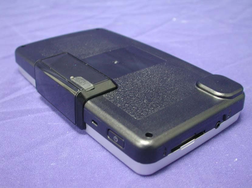
Q7M-PDR-140
Sep 28, 2006Portable Navigation Device w/ Bluetooth
Equipment Class
DSS - Part 15 Spread Spectrum Transmitter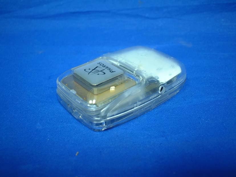
Q7M-IGPS-BTII
Jun 18, 2006Bluetooth GPS
Equipment Class
DSS - Part 15 Spread Spectrum Transmitter