Q7M-PDR-140Portable Navigation Device w/ Bluetooth
Pharos Science & Applications, Inc.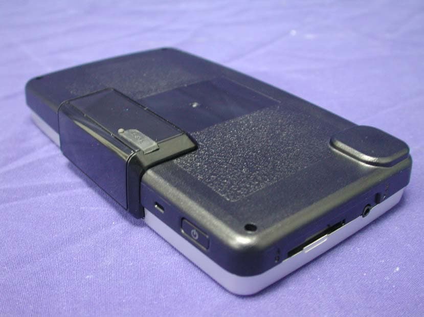
Click to zoom
Application Details
- Equipment Class
- DSS - Part 15 Spread Spectrum Transmitter
- Date of Grant
- Sep 28, 2006
- Application Purpose
- Original Equipment
- Date of Application
- Sep 27, 2006
- Equipment Note
- Portable Navigation Device w/ Bluetooth
- Frequency Range
- 2402.00000000 - 2480.00000000
- Country
- United States
Documents & Files
Document Text
Text extracted from the exhibit documents filed with the FCC. Open a document above to read the original.
Users Manual
P h a r o s D r i v e G P S 1 4 0 P o r t a b l e N a v i g a t i o n D e v i c e User Manual User instructions for operating the Pharos Drive GPS 140 Pharos Drive GPS 140 2 Introduction P h a r o s Legal NoticesCopyrightPharos Drive GPS 140 User’s ManualOriginal issue: August 2006 Pharos and the Pharos logo are registered trademarks of Pharos Inc. Other products or system names appearing in this document are trademarks or regis-tered trademarks of their respective owners. Changes may be made periodically to the i nformation in this publication with- out obligation to notify any person of such revision or changes. Such changes will be incorporated in new editions of this User’s Man ual or supplementary documents and publications.No part of this publication may be reproduced, stored in a retrieval system, or transmitted, in any form or by any means, electronic, mechanical, photocopy, recording, or otherwise, without the prior written permission of Pharos Inc.DISCLAIMER AND LIMITATION OF LIABILITYPharos and its subsidiaries makes no representations or warranties, either expressed or implied, with respect to the contents hereof and specifically dis- claims the implied warranties of merchantability or fitness for a particular pur- pose. Pharos and its subsi diaries assume no responsibi lity for any damage or loss resulting from the use of the Pharos Drive GPS 140. Revision: 1.00August 2006 NOTE: Record the device ID, serial number, purchase date, and place of pur- chase information in the space provided below. The serial number is indicated on the label affixed to your Pharos device. Al l correspondence concerning your unit should include the serial number, device ID, and purchase informa- tion. NOTE: Information in this manual is subject to change without notice. Pharos Drive GPS 140 3 Introduction P h a r o s Warnings and NoticesFor your safety, do not operate the controls of the product while driving. GPS satellite signals cannot typi cally pass through solid materials (except glass). GPS location information is not typically available inside buildings, tun-nels, or underground parking lots.A minimum of 4 GPS satellite signals is needed to calculate y our GPS position. Signal reception can be affected by weather events or overhead obstacles (e.g. dense foliage and tall buildings). Other wireless devices in the vehicle may interfere with the reception of satel-lite signals and cause the reception to be unstable.AdapterDo not attempt to service the unit. There are no serviceable parts inside. Replace the unit if it is damaged or exposed to excess moisture.Do not use the adapter if the cord becomes damaged. Connect the adapter to the proper power source. The voltage requirements are found on the product case and/or packaging. BatteryThis unit contains a non-replaceable internal Lithium Ion battery. The battery can burst or explode, releasing hazardous chemicals. To reduce the risk of fire or burns, do not disassemble, crush, puncture, or dispose of in fire or water. Use only the specified charger approved by the manufacturer. FCC WarningThe Drive GPS 140 PND has been tested and found to comply with the limits for a Class B digital device in accordance with the specifications in Part 15 of FCC rules. Operation is subject to the following two condi tions: (1) this device may not cause harmful interference, and (2) this device must accept any interference received, including interference that may cause undesired operation. This device generates, uses, and can radiate radio-frequency energy. If it is not installed and used properly, it may cause interference with radio and television reception. WARNING: The Lithium-Ion battery in the device must be recycled or dis- posed of properly. Warning: Try not to expose the Drive GPS 140 to extreme temperatures for long periods of time. These limits are designed to provide reasonable protection against harmful interference in a residential installation. This equipment generates, uses and can radiate radio frequency energy and, if not installed and used in accordance with the instructions, may cause harmful interference to radio communications. However, there is no guarantee that interference will not occur in a particular installation. If this equipment does cause harmful interference to radio or television reception, which can be determined by turning the equipment off and on, the user is encouraged to try to correct the interference by one or more of the following measures:-Reorient or relocate the receiving antenna.-Increase the separation between the equipment and receiver.-Connect the equipment into an outlet on a circuit different from that to which the receiver is connected.-Consult the dealer or an experienced radio/ TV technician for help.CAUTION:Any changes or modifications not expressly approved by the grantee of this device could void the user's authority to operate the equipment. WARNING:The equipment complies with FCC RF exposure limits set forth for an uncontrolled environment.The equipment must not be co-located or operating in conjunction with any other antenna or transmitter. Pharos Drive GPS 140 4 Table of Contents P h a r o s Table of ContentsChapter 1 Drive GPS 140 PND Fe atures and Spec ifications ........ 6 1.1 Pharos Drive GPS 140 PND features ............ .............. .............. ........6 1.2 Drive GPS 140 Specifications ......... .............. .............. .............. ........6 Chapter 2 Getting Started ................................................................ 8 2.1 Hardware overview ............................................................................8 2.1.1 Packing list ................................................................................82.1.2 Front Panel ................................................................................8 2.2 Mounting the Drive GPS 140 in your vehicle ........ .............. ...........10 2.2.1 To set up the device on your vehicle: ............................…
Text truncated - open the document above for the full version.
Cover Letter(s)
RF_160, Issue 01 Declaration of Authorization We Name: Pharos Science & Applications,Inc. Address: 411 Amapola Avenue, Torrance, CA 90501, U.S.A. City: .................................................................. . Country: U.S.A ........................................................................... . Declare that: Name: QuieTek Corp. Address: Fl.2, No.345, Xin-hu 2 nd Rd., Nei-hu District City: Taipei Country Taiwan R.O.C. is authorized to apply for Certification of the following product(s): Product description: Portable Navigation Device ..................... . Type designation: Drive GPS 140 ........................ . Trademark: Pharos on our behalf. Date: ...... 2006/9/21 ............... .. City: ...... ........................ .. Name: ...... Fred Feng ............... Signature: ... ............
External Photos
Report No.: 069L025-RF-US-P06V01 Page : 1 of 16 Version:1.0 Attachment 2 : EUT Detailed Photographs (1) EUT Photo (2) EUT Photo
ID Label/Location Info
Pharos Science & Applications,Inc. FCC ID.: Q7M-PDR-140 411 Amapola Avenue, Torrance, CA 90501, U.S.A.. Tel : 886-3-3569-666 # 2530 FCC ID AND DoC Label The FCC ID and DoC Label will be placed on the equipment as shown in the photograph below.
Internal Photos
Report No.: 069L025-RF-US-P06V01 Page : 2 of 16 Version:1.0 (3) EUT Photo (4) EUT Photo Report No.: 069L025-RF-US-P06V01 Page : 3 of 16 Version:1.0 (5) EUT Photo (6) EUT Photo Report No.: 069L025-RF-US-P06V01 Page : 4 of 16 Version:1.0 (7) EUT Photo (8) EUT Photo Report No.: 069L025-RF-US-P06V01 Page : 5 of 16 Version:1.0 (9) EUT Photo (10) EUT Photo Report No.: 069L025-RF-US-P06V01 Page : 6 of 16 Version:1.0 (11) EUT Photo (12) EUT Photo Report No.: 069L025-RF-US-P06V01 Page : 7 of 16 Version:1.0 (13) EUT Photo (14) EUT Photo Report No.: 069L025-RF-US-P06V01 Page : 8 of 16 Version:1.0 (15) EUT Photo (16) EUT Photo Report No.: 069L025-RF-US-P06V01 Page : 9 of 16 Version:1.0 (17) EUT Photo (18) EUT Photo Report No.: 069L025-RF-US-P06V01 Page : 10 of 16 Version:1.0 (19) EUT Photo (20) EUT Photo Report No.: 069L025-RF-US-P06V01 Page : 11 of 16 Version:1.0 (21) EUT Photo (22) EUT Photo Report No.: 069L025-RF-US-P06V01 Page : 12 of 16 Version:1.0 (23) EUT Photo (24) EUT Photo Report No.: 069L025-RF-US-P06V01 Page : 13 of 16 Version:1.0 (25) EUT Photo (26) EUT Photo Report No.: 069L025-RF-US-P06V01 Page : 14 of 16 Version:1.0 (27) EUT Photo (28) EUT Photo Report No.: 069L025-RF-US-P06V01 Page : 15 of 16 Version:1.0 (29) EUT Photo (30) EUT Photo Report No.: 069L025-RF-US-P06V01 Page : 16 of 16 Version:1.0 (31) EUT Photo (32) EUT Photo
RF Exposure Info
Report No. 069L025-RF-US-P06V01 Page: 1 of 3 Version: 1.0 RF Exposure Evaluation Declaration Product Name : Portable Navigation Device Model No. : Drive GPS 140 FCC ID : Q7M-PDR-140 Applicant : Pharos Science & Applications,Inc. Address : 411 Amapola Avenue, Torrance, CA 90501, U.S.A. Date of Receipt : Aug. 31, 2006 Date of Declaration: Sep. 12, 2006 Report No. : 069L025-RF-US-P06V01 The declaration results relate only to the samples calculated. The declaration shall not be reproduced except in full without the written approval of QuieTek Corporation. This report must not be used to claim product endorsement by NVLAP any agency of the U.S. Government Report No. 069L025-RF-US-P06V01 Page: 2 of 3 Version: 1.0 1. RF Exposure Evaluation 1.1. Limits According to FCC 1.1310: The criteria listed in the following table shall be used to evaluate the environment impact of human exposure to radio frequency (RF) radiation as specified in 1.1307(b) LIMITS FOR MAXIMUM PERMISSIBLE EXPOSURE (MPE) Frequency Range (MHz) Electric Field Strength (V/m) Magnetic Field Strength (A/m) Power Density (mW/cm 2 ) Average Time (Minutes) (A) Limits for Occupational/ Control Exposures 300-1500 -- -- F/300 6 1500-100,000 -- -- 5 6 (B) Limits for General Population/ Uncontrolled Exposures 300-1500 -- -- F/1500 6 1500-100,000 -- -- 1 30 F= Frequency in MHz Friis Formula Friis transmission formula: Pd = (Pout*G)/(4*pi*r 2 ) Where Pd = power density in mW/cm 2 Pout = output power to antenna in mW G = gain of antenna in linear scale Pi = 3.1416 R = distance between observation point and center of the radiator in cm Pd id the limit of MPE, 1 mW/cm 2 . If we know the maximum gain of the antenna and the total power input to the antenna, through the calculation, we will know the distance r where the MPE limit is reached. 1.2. Test Procedure Software provided by client enabled the EUT to transmit and receive data at lowest, middle and highest channel individually. The temperature and related humidity: 18°Cand 78% RH. Report No. 069L025-RF-US-P06V01 Page: 3 of 3 Version: 1.0 1.3. Test Result of RF Exposure Evaluation The maximum RF power of the EUT is 1.26 mW (1.01dBm). It is below the limit 60mW/f(GHz) = 24mW at 2.45GHz and therefore no SAR evaluation is needed.
Test Report
Report No. 069L025-RF-US-P06V01 Page: 1 of 48 Version:1.0 Test Report Product Name Portable Navigation Device Model No. Drive GPS 140 FCC ID. Q7M-PDR-140 Applicant Pharos Science & Applications,Inc. Address 411 Amapola Avenue, Torrance, CA 90501, U.S.A. Date of Receipt Aug. 31, 2006 Issued Date Sep. 12, 2006 Report No. 069L025-RF-US-P06V01 The Test Results relate only to the samples tested. The test report shall not be reproduced except in full without the written approval of QuieTek Corporation. This report must not be used to claim product endorsement by NVLAP any agency of the U.S. Government Report No. 069L025-RF-US-P06V01 Page: 2 of 48 Version:1.0 Test Report Certification Issued Date: Sep. 12, 2006 Report No.: 069L025-RF-US-P06V01 Product Name Portable Navigation Device Applicant Pharos Science & Applications,Inc. Address 411 Amapola Avenue, Torrance, CA 90501, U.S.A. Model No. Drive GPS 140 FCC ID. Q7M-PDR-140 Rated Voltage AC 120V/60Hz Working Voltage AC 120V/60Hz Trade Name Pharos Applicable Standard FCC CFR Title 47 Part 15 Subpart C: 2005 ANSI C63.4: 2003 CISPR 22: 2005 Test Result Complied The Test Results relate only to the samples tested. The test report shall not be reproduced except in full without the written approval of QuieTek Corporation. This report must not be used to claim product endorsement by NVLAP any agency of the U.S. Government Documented By : ( Rita Huang ) Tested By : ( Tom Hsieh ) Approved By : ( George Chen ) 0914 Report No. 069L025-RF-US-P06V01 Page: 3 of 48 Version:1.0 TABLE OF CONTENTS Description Page 1. GENERAL INFORMATION ...............................................................................................................5 1.1. EUT Description......................................................................................................................................5 1.2. Operational Description...........................................................................................................................8 1.3. Test System Details .................................................................................................................................9 1.4. Configuration of Test System ..................................................................................................................9 1.5. EUT Exercise Software ...........................................................................................................................9 1.6. Test Facility ...........................................................................................................................................11 2. CONDUCTED EMISSION ................................................................................................................12 2.1. Test Equipment ......................................................................................................................................12 2.2. Test Setup ..............................................................................................................................................12 2.3. Limits.....................................................................................................................................................13 2.4. Test Procedure .......................................................................................................................................13 2.5. Uncertainty ............................................................................................................................................13 2.6. Test Result of Conducted Emission .......................................................................................................14 3. PEAK POWER OUTPUT ..................................................................................................................16 3.1. Test Equipment ......................................................................................................................................16 3.2. Test Setup ..............................................................................................................................................16 3.3. Limit .....................................................................................................................................................16 3.4. Uncertainty ............................................................................................................................................16 3.5. Test Result of Peak Power Output .........................................................................................................17 4. RADIATED EMISSION .....................................................................................................................18 4.1. Test Equipment ......................................................................................................................................18 4.2. Test Setup ..............................................................................................................................................19 4.3. Limits.....................................................................................................................................................19 4.4. Test Procedure .......................................................................................................................................20 4.5. Uncertainty ............................................................................................................................................20 4.6. Test Result of Radiated Emission ..........................................................................................................21 5. BAND EDGE .......................................................................................................................................25 5.1. Test Equipment ...........................................................................................................…
Text truncated - open the document above for the full version.
Test Setup Photos
Report No.: 069L025-RF-US-P06V01 Page : 1 of 3 Version:1.0 Attachment 1: EUT Test Setup Photographs Front View of Conducted Test Back View of Conducted Test Report No.: 069L025-RF-US-P06V01 Page : 2 of 3 Version:1.0 Front View of Radiated Test Back View of Radiated Test Report No.: 069L025-RF-US-P06V01 Page : 3 of 3 Version:1.0 Front View of Radiated Test (Horn) Back View of Radiated Test (Horn)
Contact Information
Applicant
An-Chyun Wang(VP Production Manager)
Technical Contact
QuieTek CorporationJewel Chen
[email protected]886 2 8792 6808
2F, No 345, Xinhu 2d Road · Taipei · Taiwan
Test Firm
QuieTek CorporationKevin (Yu-Lung) Chen
Technical Specifications
| # | Rule Parts | Frequency Range | Power Output |
|---|---|---|---|
| 1 | 15C | 2.40 GHz - 2.48 GHz | 1.26 mW |
Other Applications from Pharos Science & Applications, Inc.
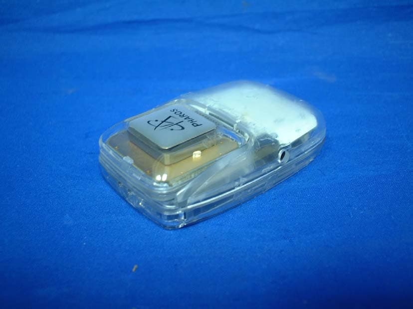
Q7M-IGPS-BTII
Jun 18, 2006Bluetooth GPS
Equipment Class
DSS - Part 15 Spread Spectrum Transmitter
Q7M-IGPS-BT
Jul 06, 2003IGPS-BT BLUETOOTH GPS RECIEVER
Equipment Class
DSS - Part 15 Spread Spectrum Transmitter