Q7O-0003802.11 Wireless Bridge
Karlnet Inc.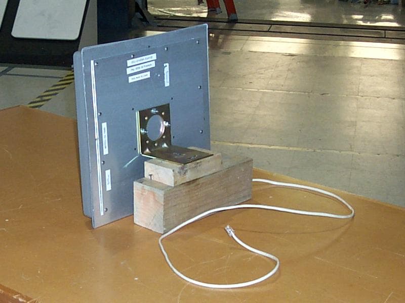
Click to zoom
Application Details
- Equipment Class
- DTS - Digital Transmission System
- Date of Grant
- Feb 25, 2004
- Application Purpose
- Original Equipment
- Date of Application
- Feb 25, 2004
- Equipment Note
- 802.11 Wireless Bridge
- Frequency Range
- 2412.00000000 - 2462.00000000
- Company
- Karlnet Inc.
- Country
- United States
Documents & Files
Document Text
Text extracted from the exhibit documents filed with the FCC. Open a document above to read the original.
Users Manual
525 Metro Place North, Suite 100 Dublin, OH 43017 Office: 614-822-5275 Fax: 614-822-0024 www.KarlNet.com 1 KarlNet KarlNet Inc. Networking your Wireless World KarlNet Customer Premise Equipment (CPE) Outdoor Family of Products Setup and Installation Manual (Rev. B) Small-Office Subscriber Units (Model Number SSU-0124BR-SGxxxx) Corporate Subscriber Units (Model Numbers CSU-0124BR-SGxxxx) © 2003 KarlNet, Inc. All rights reserved. Printed in the U.S.A 525 Metro Place North, Suite 100 Dublin, OH 43017 Office: 614-822-5275 Fax: 614-822-0024 www.KarlNet.com 2 KarlNet TABLE OF CONTENTS TABLE OF CONTENTS.................................................................................................... 2 FCC NOTICE .....................................................................................................................3 WARRANTY ..................................................................................................................... 4 PRODUCT DESCRIPTION ............................................................................................... 5 PACKING LIST ................................................................................................................. 6 THEORY OF OPERATIONS ............................................................................................ 7 FEATURES ........................................................................................................................8 INSTALLATION ............................................................................................................... 9 Mount the Unit ................................................................................................................ 9 General Mounting Considerations .............................................................................. 9 Power up the Unit ........................................................................................................... 9 Configure the Unit ........................................................................................................ 11 Align and Test the Unit................................................................................................. 11 Before Running the Link Test................................................................................... 11 Running the Link Test .............................................................................................. 16 CONTACT........................................................................................................................21 525 Metro Place North, Suite 100 Dublin, OH 43017 Office: 614-822-5275 Fax: 614-822-0024 www.KarlNet.com 3 KarlNet FCC Declaration of Conformity Responsible party: KarlNet, Inc. 525 Metro Place N., Suite 100 Dublin, OH 43017 (614) 822 – 5275 Fax: (614) 822 - 2400 We, KarlNet, Inc. declare that the wireless networking equipment described herein : (1) Compleis with FCC radiation exposure limits set forth for an uncontrolled environment when installed as directed. (2) Meets Class B emission requirements and complies with Part 15 of the FCC rules. Operation is subject to the following two conditions: • This device may not cause harmful interference. • This device must accept any interference received, including interference that may cause undesired operation. FCC Notice This equipment should be professionally installed, and the installer is responsible for ensuring that the system is used exclusively for fixed, point-to-point or fixed point-to- multipoint operations. The equipment should be installed and operated as fix-mounted antennas such that the main lobe(s) of these antennas are located a minimum of 2 meters between the antenna and all persons during normal operation. Users and installers must adhere to the antenna installation instructions and transmitter operating conditions for satisfying RF exposure compliance set forth under Part 15 of the FCC regulations. Failure to do so, or changing/modifying the unit may void the user’s authority to operate the equipment. 2004 KarlNet, Inc. All Rights Reserved. No part of parts of this document may be reproduced, translated, stored in any electronic retrieval system or transmitted, in any form or by any means, electronic, mechanical, photocopied, recorded or otherwise, without the prior written permission of KarlNet, Inc. 525 Metro Place North, Suite 100 Dublin, OH 43017 Office: 614-822-5275 Fax: 614-822-0024 www.KarlNet.com 4 KarlNet WARRANTY KarlNet, Inc. warrants that your device is free of defects in material and workmanship for a period of one year after initial purchase. KarlNet will, in this period of time, repair or replace, any KarlNet product returned to the factory, freight prepaid. The KarlNet warranty covers repairs or replacement (at KarlNet’s option) of the product only. KarlNet is not responsible for the cost of removal, reinstallation, or shipping to the place of repair. KarlNet does not extend or modify its warranty period as a result of repair or replacement. KarlNet reserves the right to void a warranty and/or make reasonable charges for repair of a unit if the warranty seal is broken or the unit displays evidence of misuse, abuse, or tampering. KarlNet is not responsible for damage to any other equipment or property, or any other consequential or incidental damages of any kind, whether based on contract, negligence, or strict liability. Maximum liability shall not in any case exceed the purchase price of the unit. Warranties give you (the buyer) specific legal rights. You may also have other rights that vary from state to state. This warranty is only extended to purchases made in the United States of America or its possessions. SPECIAL WARRANTY NOTICE The system warranty is null and void if any of the following occurs: 1. The product enclosure is opened. 2. The system connections are not properly waterproofed. 3. The device is installed improperly or with incorrect connectors. 4. The antenna or DC …
Text truncated - open the document above for the full version.
Users Manual
525 Metro Place North, Suite 100 Dublin, OH 43017 Office: 614-822-5275 Fax: 614-822-0024 www.KarlNet.com 1 KarlNet KarlNet Inc. Networking your Wireless World KarlNet Residential Subscriber Unit (RSU) Setup and Installation Manual Residential Subscriber Unit (Model Number RSU-01101) © 2003 KarlNet, Inc. All rights reserved. Printed in the U.S.A 525 Metro Place North, Suite 100 Dublin, OH 43017 Office: 614-822-5275 Fax: 614-822-0024 www.KarlNet.com 2 KarlNet TABLE OF CONTENTS TABLE OF CONTENTS.................................................................................................... 2 FCC NOTICE ....................................................................Error! Bookmark not defined. WARRANTY ..................................................................................................................... 3 PRODUCT DESCRIPTION ............................................................................................... 4 THEORY OF OPERATIONS ............................................................................................ 7 FEATURES ........................................................................................................................8 Hardware/Environmental Features ............................................................................. 8 INSTALLATION ............................................................................................................... 9 Mount the Unit .............................................................................................................. 10 General Mounting Considerations ............................................................................ 10 Power up the Unit ......................................................................................................... 11 Configure the Unit ........................................................................................................ 12 CONTACT........................................................................................................................14 525 Metro Place North, Suite 100 Dublin, OH 43017 Office: 614-822-5275 Fax: 614-822-0024 www.KarlNet.com 3 KarlNet FCC Declaration of Conformity Responsible party: KarlNet, Inc. 525 Metro Place N., Suite 100 Dublin, OH 43017 (614) 822 – 5275 Fax: (614) 822 - 2400 We, KarlNet, Inc. declare that the wireless networking equipment described herein : (1) Compleis with FCC radiation exposure limits set forth for an uncontrolled environment when installed as directed. (2) Meets Class B emission requirements and complies with Part 15 of the FCC rules. Operation is subject to the following two conditions: • This device may not cause harmful interference. • This device must accept any interference received, including interference that may cause undesired operation. FCC Notice This equipment should be professionally installed, and the installer is responsible for ensuring that the system is used exclusively for fixed point-to-multipoint operations. The equipment should be installed and operated as fix-mounted antennas such that the main lobe(s) of these antennas are located a minimum of 2 meters between the antenna and all persons during normal operation. Users and installers must adhere to the antenna installation instructions and transmitter operating conditions for satisfying RF exposure compliance set forth under Part 15 of the FCC regulations. Failure to do so, or changing/modifying the unit may void the user’s authority to operate the equipment. 2004 KarlNet, Inc. All Rights Reserved. No part of parts of this document may be reproduced, translated, stored in any electronic retrieval system or transmitted, in any form or by any means, electronic, mechanical, photocopied, recorded or otherwise, without the prior written permission of KarlNet, Inc. 525 Metro Place North, Suite 100 Dublin, OH 43017 Office: 614-822-5275 Fax: 614-822-0024 www.KarlNet.com 4 KarlNet WARRANTY KarlNet, Inc. warrants that your device is free of defects in material and workmanship for a period of one year after initial purchase. KarlNet will, in this period of time, repair or replace, any KarlNet product returned to the factory, freight prepaid. The KarlNet warranty covers repairs or replacement (at KarlNet’s option) of the product only. KarlNet is not responsible for the cost of removal, reinstallation, or shipping to the place of repair. KarlNet does not extend or modify its warranty period as a result of repair or replacement. KarlNet reserves the right to void a warranty and/or make reasonable charges for repair of a unit if the warranty seal is broken or the unit displays evidence of misuse, abuse, or tampering. KarlNet is not responsible for damage to any other equipment or property, or any other consequential or incidental damages of any kind, whether based on contract, negligence, or strict liability. Maximum liability shall not in any case exceed the purchase price of the unit. Warranties give you (the buyer) specific legal rights. You may also have other rights that vary from state to state. This warranty is only extended to purchases made in the United States of America or its possessions. SPECIAL WARRANTY NOTICE The system warranty is null and void if any of the following occurs: 1. The product enclosure is opened. 2. The system connections are not properly waterproofed. 3. The device is installed improperly or with incorrect connectors. 4. The antenna or DC Power Injector are physically damaged. 5. The device is operated outside the recommended DC power specifications. 6. The device is damaged by extreme forces of nature, lightning, or ‘Acts of God.’ PRODUCT DESCRIPTION 525 Metro Place North, Suite 100 Dublin, OH 43017 Office: 614-822-5275 Fax: 614-822-0024 www.KarlNet.com 5 KarlNet Thank you for purchasing KarlNet’s Residential Subscriber Unit (RSU) outdoor wireless networking device. This guide explains how to install the hardware device, provides power and cabling guidelines, a…
Text truncated - open the document above for the full version.
Cover Letter(s)
NCEE NEBRASKA CENTER FOR EXCELLENCE IN ELECTRONICS 4740 Discovery Drive Lincoln, NE 68521 402-472-5880 18 February 2004 Response to ATCB Review RE: KarlNet, Inc. FCC ID: Q7O-0003 Mr Johnson: Below you will find the a response to your letter dated 9 February 2004: 1) The modular request letter mentions different software loads. What is the difference in software (i.e. does the software load affect power or any other parameters affecting FCC compliance). A revised modular request letter has been uploaded to the ATCB website. The software loads effect the duty cycle of the product, testing was performed at the maximum duty cycle possible with the product. 2) The modular request letter mentions specific configurations are requested to be approved; different software loads. A revised modular request letter has been uploaded to the ATCB website. The software loads are designed to allow the product to interface with specific hardware and to allow a customer to purchase a product geared more towards their particular application. The software loads do not affect the RF characteristics. 3) It is uncertain why a modular application is being requested. Currently the grant would be limited to KarlNet applications only, in enclosures as specified in the application, and only to specific interface boards. It seems you would have more flexibility with a normal grant. Please call to discuss. Tim, thank you for your input and clarification in on phone conversation Monday February 10 th . At this time the plan is to continue with the modular approval. 4) The modular approval letter limits the use of the approval to specific antennas, interface cards, etc. However the operational description mentions "various end- use items". This does not agree with the intent of the modular approval. Please adjust the documentation accordingly. The various end “use items” are all supplied by KarlNet, Inc. and are or will be incorporated in the table shown in the modular approval letter. 5) Please provide external photographs of the antenna/device. Uploaded back and front pictures of Arc Wireless 19dBi system on 10 February 2004. 6) Please provide a sample label for the exterior of the device. This should include appropriate statements as specified by 15.18. A sample label for the exterior of the device has been uploaded for compliance to 15.19 on 17 February 2004. 7) The parts lists should clearly show that the card is OEM equipment from another manufacturer. Additionally, is confidentiality requested for the parts list? If so, please adjust the confidentiality letter. KarlNet has agreed to alter the parts list to specify FCC ID: IXMPCBAG, or equivalent as item 4. The “Item Master” form from the KarlNet inventory control software has been uploaded to show this. Also a modified letter of confidentiality was uploaded 17 February 2004. 8) Internal photographs of the PCMCIA card must be provided as part of the internal photographs, including photographs under all subshields. Many of these photos appear in the test report. Please provide as part of the separate exhibit for internal photographs. Uploaded top and bottom pictures with and without shielding on 10 February 2004. 9) Please provide specifications sheets for each of the proposed antennas. Please provide additional photographs of the antennas if the spec. sheets do not clearly show the antennas. Specifications information on the four antennas listed was uploaded to the ATCB servers 17 February 2004. 10) Please provide test photographs for the radiated tests as a separate exhibit. Uploaded one radiated test photo and two conducted test photos on 10 February 2004. 11) Section 2.3 of the test report appears to mention a modification. It is assumed that this will be implemented into all production units. Please clarify. The modification as discussed was previously implemented in production and the unit that is shipped with products contains this modification. The power supply provided for testing was an older unit and did not have the ferrite. 12) Pages 6-7 mention bandedge peak/average emissions. It appears the peak are in excess of the average readings. Additionally these measurements appear over the limits. Please explain. This is due to the duty cycle as discussed, the VBW settings were changed and the measurement repeated per your suggestion and the new figures have been incorporated in the report. 13) For AC line conducted measurements, the AC line cord appears to be draping to the floor vs. tied down as specified in ANSI C63.4. Please adjust and retest as necessary. Retested results and photos have been placed in the report. There was no significant change in the results. 14) Please explain why the automated scans may have shown higher values than the manual scans. The results are placed on the figure manually after being verified and corrected, the figures in question were not corrected. The correct plots have been added to the report. 15) The test report states "The conducted average measurements were affected by the non-continuous signal from the RF transmitter" (page 7). However page 5, section 4.2 implies the device can be set to continuous mode. Please explain. Note that normally the peak/average delta for these types of devices is about 8- 11 dB, while the radiated results submitted appear around 19 dB between peak and average by looking at the fundamental. This suggests the device was not continuously transmitting and the VBW must be carefully selected during testing. Note that the FCC test methods are expecting the device to be placed into 100% TX mode of operation. Therefore, please confirm what VBW settings were used for average measurements > 1 GHz? Note that the use of 10 Hz expects the device to be placed into 100% TX with no associated duty cycle. If a duty cycle is present, the VBW must be > than the 1/Txon time. Please provide information regarding the TX on/off time and period. Duty cycle information and discussion has been added to the report in S…
Text truncated - open the document above for the full version.
Cover Letter(s)
February 17, 2004 To: Federal Communications Commission 7435 Oakland Mills Road Columbia, Maryland 21046 Subject: Limited Modular Approval of FCC ID: Q7O-0003 On behalf of KarlNet, Inc., I request a limited modular approval for KarlNet part number PRA-0005 with FCC ID: Q7O-0003. The limited modular approval is based on the requirements set out in Public Notice DA 00-1407. 1) RF Shielding – The RF chipset on the PRA-0005 is covered by two metal shields as shown in the test report submitted with this application. One of the two shields is electrically tied to the metal PCMCIA housing using copper fingers. 2) Buffered modulation/data inputs – The PRA-0005 card uses the Agere chipset for buffering the input. The chipset includes the WL60010 MAC, N4080 Baseband Controller, and W4050 RF Transceiver. 3) Power supply regulation – The PRA-0005 card uses the interface boards for the power supply regulation. The LM2592-5 chip in the schematic on KarlNet part numbers KN-100 (WPRG+) and KN-50 (Blackbird) provide for the regulation. The limited modular approval will limit the PRA-0005 card to the KarlNet interface boards with voltage regulation provided. 4) Antenna requirements of Parts 15.203 and 15.204(c) – Photos of the connector and how the PRA-0005 resides inside the antenna are shown in the test report. 5) Stand alone testing – The limited modular approval will limit the PRA-0005 card and interface boards to use the enclosures of the list of antennas in Table 1. 6) FCC ID Labeling – A photo of proper labeling has been submitted with this application. 7) Specific FCC rules – The EUT complies with FCC Parts 15.209 and 15.247 as shown in the test report submitted with this application. 8) RF exposure – The EUT complies with FCC Part 247(b)(4). The calculations have been submitted in a separate document with this application. Table 1 outlines combinations utilized with KarlNet, Inc. Radio card P/N: PRA-0005 for which KarlNet, Inc. is applying for a grant of certification (FCC ID: Q7O-0003) with modular approval with said radio and a minimum pigtail length of 4”. FCC ID: Q7O-0003 KarlNet, Inc. P/N: PRA-0005 is: • USI P/N : 8601-114111-20 o Cardbus 802.11b 35mW Agere HermesII radio with Thin built-in-antenna o Previously FCC certified with FCC ID: IXMPCBAG • Proprietary pigtail provided by KarlNet, Inc. (All Pigtail lengths are required to be 4 inches or greater.) Table 1, below, lists the combinations of antenna and interface boards approved by KarlNet, Inc for use. Any additional combinations, not presently listed below, must be approved by KarlNet, Inc. KN-100 WPRG+ represents a FCC-Class B verified PCB consisting of P/N BA200-0107 and upgrades. KN-50 Blackbird represents a FCC-Class B verified PCB consisting of P/N BA201-0201 and upgrades. TurboCell (Base, Client), Xavier, and Nova represent various software loads developed by KarlNet, Inc. Key: “T” = Tested “A” = Approved by similarity or lower gain “-” = Configuration does not exist KN-100 WPRG+ [TurboCell] KN-100 WPRG+ [Access Point] KN-50 Blackbird [Xavier] KN-50 Blackbird [Nova] Antenna Type Gain Arc Wireless FWA-SL-19-2.4-001-INT Flat panel 19dbi T A A A Telex 2474KN Flat panel 18dbi A A A A Arc Wireless FWA-VR-13-2.45-INT Flat panel 13dbi A A A A KarlNet Inc. ANT-0005 Flat panel 6dbi - - A A Table 1 Product Matrix If there are any questions please feel free to contact me: [email protected] or (402) 472-5880. Sincerely, Doug Kramer Lab Manager Nebraska Center for Excellence in Electronics
Operational Description
-25 -20 -15 -10 -5 0 5 10 15 20 0 10 20 30 40 50 60 70 80 90 100 110 120 130 140 150 160 170 180 -170 -160 -150 -140 -130 -120 -110 -100 -90 -80 -70 -60 -50 -40 -30 -20 -10 TELEX COMMUNICATIONS, INC.8601 E. CORNHUSKER HWY.LINCOLN, NE 68507PHONE: (800) 898-6723FAX: (402) 467-3279WWW.TELEX.COM/WIRELESSMODEL: 2473AA 18 dBi Patch Array Freq: 2.400 GHz Freq: 2.442 GHz Freq: 2.484 GHz Magnitude (dBi) vs. Azimuth (Deg) -25 -20 -15 -10 -5 0 5 10 15 20 0 10 20 30 40 50 60 70 80 90 100 110 120 130 140 150 160 170 180 -170 -160 -150 -140 -130 -120 -110 -100 -90 -80 -70 -60 -50 -40 -30 -20 -10 TELEX COMMUNICATIONS, INC.8601 E. CORNHUSKER HWY.LINCOLN, NE 68507PHONE: (800) 898-6723FAX: (402) 467-3279WWW.TELEX.COM/WIRELESSMODEL: 2473AA 18 dBi Patch Array Freq: 2.400 GHz Freq: 2.442 GHz Freq: 2.484 GHz Magnitude (dBi) vs. Azimuth (Deg)
Operational Description
Antenna Performance Frequency2.45 GHz (center) Gain13 dBi Antenna design Four patch PolarizationLinear Bandwidth100 MHz Horizontal beamwidth38° Vertical bandwidth38° VSWR1.5:1 F/B Ratio>30 dB Maximum power input100 watt Lighting protectionDirect ground Physical Characteristics Dimensions8.5 x 8.5 x 1.125 in (21.6 x 21.6 x 2.8 cm) Case colorGray, other colors available on custom order ConnectorN type female Case materialHigh impact UV stabilized plastic, ultrasonically welded Wind/ice loading area - in² (cm²)72 (466) Rated wind velocity - mph (km/h)120 (241.5) Lateral thrust @100 mph-lbs (kg)10 (22) Torsional moment @ 100 mph with standard mounting - ft/lbs (m/kg) 0.2 (0.22) Page 1 of 1Low Distribution Price. 13 dBi Panel Directional Antenna with the adjustable mount WR... 2/16/2004http://www.winncom.com/moreinfo/item/WRP2400-12/index.html
Operational Description
Antenna Performance Frequency2.45 GHz (center) Gain19 dBi Antenna design Sixteen patch PolarizationLinear Bandwidth 1.5:1 VSWR100 MHz Horizontal beamwidth18° Vertical bandwidth18° F/B Ratio>30 dB Cross polarization>30 dB Maximum power input100 watt Lighting protectionDirect ground Physical Characteristics Dimensions15.5 x 15.5 x 1.125 in (39.4 x 39.4 x 2.8 cm) Case colorGray, other colors available on customer order ConnectorN type female Case materialHigh impact UV stabilized plastic, ultrasonically welded Wind/ice loading area - in² (cm²)240 (1552) Lateral thrust @ 100 mph-lbs (kg)15 (33) Torsional moment @ 100 mph with standard mounting - ft/lbs (m/kg) 0.4 (0.88) Page 1 of 1Low Distribution Price. 19 dBi Directional Panel Antenna with Adjustable Mount, 2.400-... 2/16/2004http://www.winncom.com/moreinfo/item/WRP2400-18/index.html
Operational Description
48 Perimeter Road, Manchester, NH 03103 • Phone: 603-627-7877 • Fax: 603-627-1764 • E-mail: [email protected] Web Site: www.cushcraft.com COMMUNICATIONS ANTENNAS 2.4 GHz Panel Antenna The S2406P antenna has been designed to provide users of 2.4 GHz. systems with an antenna offering 6+ dBi of directional gain in a package that can be easily hidden or disguised. The antenna can either be wall mounted to provide directional coverage or ceiling mounted if there is a desire to direct or focus signal into a coverage area from a ceiling mount location. There is an articulating mount available for the antenna. The articulating mount allows the antenna to be oriented both in azimuth and elevation. The antenna's most compelling feature is its total size. The antenna is only 5.2" X 3.8" X 1/2" deep in total. As such the antenna can be conveniently mounted in very confined spaces and disguised if need be. H-Plane E-Plane S2406P • Small, easy to disguise package aesthetically neutral • Wall and ceiling mount • UV stabile indoor/outdoor housing 2.4 GHz ANTENNA SPECIFICATION CHART PRODUCT DATA SHEET S2406P 330° -10 -15 120° 150° 180° 240° -5 -5 -5 -10 -10 -15 -15 90° 0º -5 -10 -15 30° 60° 270° 300° 210° -20 -20 -20 -20 ModelFreq.GainVSWRPolarization-3dB bmwidthWeightRF ConnectorDimensionsPowerMount MHzdBiE-Plane H-Planelb (kg)(f)in. (cm)(Watts)Style S2406P2400-250061.8:1Linear65º 70º.5 (.23)N5.2 x 3.8 x 1/2 (13.2 x 9.7 x 1.4)10Wall/Surface
Operational Description
525 Metro Place North, Suite 100 Dublin, OH 43017 Office: 614-822-5275 Fax: 614-822-0024 www.karlnet.com KarlNet Theory of Operation KarlNet, Inc. utilizes the PRA-0005 (FCC ID:Q7O-0003) 802.11b Radio card to incorporate them into various end-items, which are sold throughout the wireless-data industry through OEMs, channel partners, and direct sales. These products include, but not limited to, Wireless- Base Stations and Wireless-Clients forming the core of a point-to-multipoint outdoor wireless networks. The following diagram illustrates typical KarlNet, Inc. provided end-items that utilize this modular certification. CEV/Enclosure W BS CEV KarlNet System Products Products at a glance Internet CSU CSU (unlimited users) PoE DC Pwr Ethernet Ethernet E thernet Hub/Switch CSU CSU (unlimited users) PoE DC Pwr Ethernet Ethernet Ethernet Hub/Switch RSU (5 users) PoE DC Pwr Ethernet Ethernet E thernet Hub/Switch RSU SSU (12 users) PoE DC Pwr Ethernet Ethernet Ethernet Hub/S witch SSU Radius Auth WBS
RF Exposure Info
FCC ID: Q7O-0003 Page 1 of 1 RF Exposure Statement 18-Feb-2004 FCC ID: Q7O-0003 RF Exposure Statement for KarlNet PRA-0005. Notice in Installation Manual: FCC Radiation Exposure Statement This antenna/transmitter device must be fixed-mounted on outdoor permanent structures with a separation distance of at least 2 meters from all persons. Users and installers must adhere to the antenna installation instructions and transmitter operating conditions for satisfying RF exposure compliance set forth under Part 15 of the FCC regulations. RF Exposure Calculations: The following information provides the minimum separation distance for the 19 dBi antenna provided as an integral part of KarlNet PRA-0005, as calculated from FCC OET 65 Appendix B, Table 1B Guidelines for General Population/Uncontrolled Exposure. This calculation is based on the highest EIRP possible from the system, considering maximum power and antenna gain, and considering a 1.0 mW/cm^2 uncontrolled exposure limit. The formula used was: S = (Po * G) / (4 * Pi * r^2) or r = SQRT [ (Po * G) / (4 * Pi * S) ] Where S = 1.0 mW/cm^2 for 2400 MHz Where Po = 0.061 W (Channel 1: 17.85dBm) Where G = 79.5 (numeric equivalent to 19 dBi antenna gain) Where r = Minimum Safe Distance from antenna (cm) For PRA-0005 series, r = 19.64 cm Notes: 1. The minimum safe distance is based on a conservative “worse case” prediction, i.e. using the formula shown above and no duty factor. In practice the minimum distance could be much shorter. (Ref. 2) 2. The minimum safe distance has been calculated for the maximum allowed Power Density (S) limit of 1.0 mW/cm^2 in the frequency range 1500-100,000 MHz for uncontrolled environments (Ref. 2). 3. The users manual and all documentation for this product recommend a minimum distance of 2m even though the calculated value is 19.64cm, as this product is intended for fixed installations. References: 1. FCC Part 15, sub-clause 15.247 (b) (4) (i) 2. FCC OET Bulletin 65, Edition 97-01 3. FCC Supplement C to OET Bulletin 65, edition 01-01
Test Report
R120403-01-0 FCC ID: Q7O-0003 NCEE NEBRASKA CENTER FOR EXCELLENCE IN ELECTRONICS 4740 Discovery Drive Lincoln, NE 68521 402-472-5880 Test Report Company: KarlNet, Inc 525 Metro Place North, Ste 100 Dublin, OH 43017 Contact: Kedar Kapoor Product: SSU-01H2BR-SG4100 FCC ID: Q7O-0003 Test Report No: R120403-01-0 APPROVED BY: Steve Cass _________________________ General Manager Doug Kramer _________________________ Test Engineer DATE: 23 February 2004 Total Pages: 72 The Nebraska Center for Excellence in Electronics (NCEE) authorizes the above named company to reproduce this report provided it is reproduced in its entirety for use by the company’s employees only. Any use that a third party makes of this report, or any reliance on or decisions made based on it, are the responsibility of such third parties. NCEE accepts no responsibility for damages, if any, suffered by any third party as a result of decisions made or actions based on this report. This report applies only to the items tested. NCEE is a FCC registered lab. Registration #100875 NCEE R120403-01-0 FCC ID: Q7O-0003 Page 2 of 72 Table of Contents 1.0 Summary of test results 1.1 Test Results 1.2 Test Methods 1.2.1 Conducted Emissions 1.2.2 Radiated Emissions 2.0 Description 2.1 Equipment under test 2.1.1 Identification 2.1.2 EUT received date 2.1.3 EUT tested dates 2.1.4 Manufacturer 2.1.5 Serial number 2.2 Laboratory description 2.3 Special equipment or setup 3.0 Test equipment used 4.0 Detailed Result…
Text truncated - open the document above for the full version.
Contact Information
Applicant
Kedar P Kapoor(Sr. Software Engineer)
Technical Contact
KarlNetKedar Kapoor
[email protected](614)822-5275
525 Metro PI N Ste 100 · Dublin, Ohio · United States
Non-Technical Contact
KarlNetDoug Karl
[email protected](614)822-5275
Test Firm
Nebraska Center for Excellence in ElectronicsSteve Cass
Technical Specifications
| # | Rule Parts | Frequency Range | Power Output |
|---|---|---|---|
| 1 | 15C | 2.41 GHz - 2.46 GHz | 61.00 mW |
Other Applications from Karlnet Inc.
Q7O-0004
May 09, 2004802.11 a/b/g Mini-PCI Card
Equipment Class
DTS - Digital Transmission System
Q7OKS-CPO010124B
Oct 06, 2003802.11 Wireless Bridge
Equipment Class
DTS - Digital Transmission System