Q7OKS-CPO010124B802.11 Wireless Bridge
Karlnet Inc.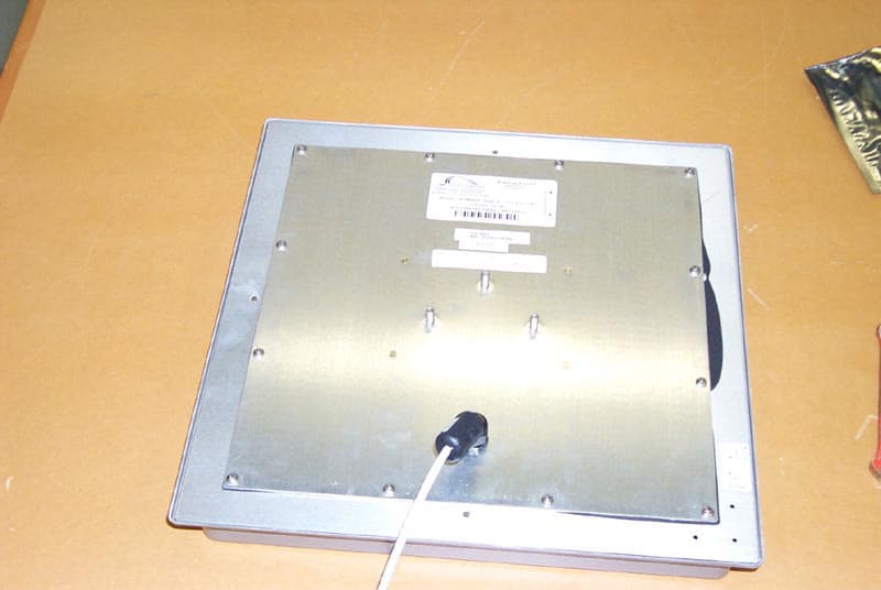
Click to zoom
Application Details
- Equipment Class
- DTS - Digital Transmission System
- Date of Grant
- Oct 06, 2003
- Application Purpose
- Original Equipment
- Date of Application
- Oct 06, 2003
- Equipment Note
- 802.11 Wireless Bridge
- Frequency Range
- 2412.00000000 - 2462.00000000
- Company
- Karlnet Inc.
- Country
- United States
Documents & Files
Document Text
Text extracted from the exhibit documents filed with the FCC. Open a document above to read the original.
Users Manual
525 Metro Place North, Suite 100 Dublin, OH 43017 Office: 614-822-5275 Fax: 614-822-0024 www.karlnet.com KarlNet KarlNet Inc. Networking your Wireless World KarlNet Customer Premise Equipment (CPE) Outdoor Family of Products Setup and Installation Manual (Rev. A) Small-Office Subscriber Units (Model Number SSU-0124BR-SG4260) Corporate Subscriber Units (Model Numbers CSU-0124BR-SG4200 and CSU- 0124BR-SG4201) © 2003 KarlNet, Inc. All rights reserved. Printed in the U.S.A 1 525 Metro Place North, Suite 100 Dublin, OH 43017 KarlNet Office: 614-822-5275 Fax: 614-822-0024 www.karlnet.com TABLE OF CONTENTS TABLE OF CONTENTS....................................................................................................2 FCC NOTICE.....................................................................................................................3 WARRANTY.....................................................................................................................4 PRODUCT DESCRIPTION...............................................................................................5 PACKING LIST.................................................................................................................6 THEORY OF OPERATIONS............................................................................................7 FEATURES........................................................................................................................8 INSTALLATION...............................................................................................................9 Mount the Unit................................................................................................................9 General Mounting Considerations..............................................................................9 Power up the Unit...........................................................................................................9 Configure the Unit........................................................................................................11 Align and Test the Unit.................................................................................................11 Before Running the Link Test................................................................................... 11 Running the Link Test..............................................................................................16 CONTACT........................................................................................................................20 2 525 Metro Place North, Suite 100 Dublin, OH 43017 KarlNet Office: 614-822-5275 Fax: 614-822-0024 www.karlnet.com FCC NOTICE KarlNet, Inc. wireless networking equipment described herein complies with FCC radiation exposure limits set forth for an uncontrolled environment when installed as directed. The equipment should be installed and operated as fix-mounted antennas such that the main lobe(s) of these antennas are located a minimum of 2 meters between the antenna and all persons during normal operation. This device complies with Part 15 of the FCC rules. Operation is subject to the following two conditions: 1. This device may not cause harmful interference. 2. This device must accept any interference received, including interference that may cause undesired operation. FCC Notice This antenna/transmitter device must be fixed-mounted on outdoor permanent structures with a separation distance of at least 2 meters from all persons. Users and installers must adhere to the antenna installation instructions and transmitter operating conditions for satisfying RF exposure compliance set forth under Part 15 of the FCC regulations. 2003 KarlNet, Inc. All Rights Reserved. No part of parts of this document may be reproduced, translated, stored in any electronic retrieval system or transmitted, in any form or by any means, electronic, mechanical, photocopied, recorded or otherwise, without the prior written permission of KarlNet, Inc. 3 525 Metro Place North, Suite 100 Dublin, OH 43017 KarlNet Office: 614-822-5275 Fax: 614-822-0024 www.karlnet.com WARRANTY KarlNet offers a warranty covering a period of 90 days from the date of purchase by the retail customer. If a product is found defective during the warranty period, KarlNet will repair or replace the product with the same or a similar model, which may be a reconditioned unit, without charge for parts or labor. IN NO EVENT SHALL KARLNET BE LIABLE TO YOU OR ANY OTHER PARTY FOR ANY DIRECT, INDIRECT, GENERAL, SPECIAL, INCIDENTAL, CONSEQUENTIAL, EXEMPLARY OF OTHER DAMAGE ARISING OUT OF THE USE OR INABILITY TO USE THE PRODUCT (INCLUDING, WITHOUT LIMITATION, DAMAGES FOR LOSS OF BUSINESS PROFITS, BUSINESS INTERRUPTION, LOSS OF BUSINESS INFORMATION OR ANY OTHER PECUNIARY LOSS, OR FROM ANY BREACH OF WARRANTY, EVEN IF KARLNET HAS BEEN ADVISED OF THE POSSIBILITY OF SUCH DAMAGES. (Some states do not allow the exclusion or limitation of incidental or consequential damages, so the above exclusion or limitation may not apply to you.) IN NO CASE SHALL KARLNET’S LIABILITY EXCEED THE AMOUNT YOU PAID FOR THE PRODUCT. 4 525 Metro Place North, Suite 100 Dublin, OH 43017 KarlNet Office: 614-822-5275 Fax: 614-822-0024 www.karlnet.com PRODUCT DESCRIPTION Thank you for purchasing KarlNet’s Customer Premise Equipment (CPE) Outdoor wireless networking devices. This guide explains how to install the hardware devices, and provides power and cabling guidelines. KarlNet offers two high-speed outdoor CPE networking systems that provide point-to- multipoint and point-to-point connectivity to enterprise and service providers. The TurboCell Small Office Subscriber Unit (SSU) is designed specifically for medium-to-large fixed wireless networks that demand higher performance because of high traffic. The SSU is used as a remote station that connects to a KarlNet WISP base station (WBS), and can be used in either a point-to-point or point-to-multipoint network. …
Text truncated - open the document above for the full version.
ID Label/Location Info
TurboCell Subscriber Unit FOR HOME OR OFFICE USE Assy P/N : KS-CPO-0101-24B-R01 FCC ID :Q7OKS-CPO010124B POLARIZATION Tested To Comply With FCC Standard
Operational Description
THEORY OF OPERATIONS KarlNet’s CPE Outdoor wireless devices are used as remote stations that connect to a base station or repeater, and are used in both point-to-point and point-to-multipoint networks. They provide low cost, easy to install solutions for small office or large business locations. The following diagram illustrates how KarlNet’s CPE outdoor devices are used within the wireless network.
RF Exposure Info
FCC ID: Q7OKS-CPO010124B RF Exposure Statement for KarlNet KS-CPO-0101-24B-Xxx series: Notice in Installation Manual: FCC Radiation Exposure Statement This antenna/transmitter device must be fixed-mounted on outdoor permanent structures with a separation distance of at least 2 meters from all persons. Users and installers must adhere to the antenna installation instructions and transmitter operating conditions for satisfying RF exposure compliance set forth under Part 15 of the FCC regulations. RF Exposure Calculations: The following information provides the minimum separation distance for the 18 dBi antenna provided as an integral part of KarlNet KS-CPO-0101-24B-Xxx series product, as calculated from FCC OET 65 Appendix B, Table 1B Guidelines for General Population/Uncontrolled Exposure. This calculation is based on the highest EIRP possible from the system, considering maximum power and antenna gain, and considering a 1.0 mW/cm^2 uncontrolled exposure limit. The formula used was: S = (Po * G) / (4 * Pi * r^2) or r = SQRT [ (Po * G) / (4 * Pi * S) ] Where S = 1.0 mW/cm^2 for 2400 MHz Where Po = 0.032 mW (Peak RF from IMRWLPCE24H grant) Where G = 63.1 (numeric equivalent to 18 dBi antenna gain) Where r = Minimum Safe Distance from antenna (cm) For KS-CPO-0101-24B-Xxx series, r = 40 cm Notes: 1. The minimum safe distance is based on a conservative “worse case” prediction, i.e. using the formula shown above and no duty factor. In practice the minimum distance could be much shorter. (Ref. 2) 2. The minimum safe distance has been calculated for the maximum allowed Power Density (S) limit of 1.0 mW/cm^2 in the frequency range 1500-100,000 MHz for uncontrolled environments (Ref. 2). 3. The users manual and all documentation for this product recommend a minimum distance of 2m even though the calculated value is 40cm, as this product is intended for fixed installations. References: 1. FCC Part 15, sub-clause 15.247 (b) (4) (i) 2. FCC OET Bulletin 65, Edition 97-01 3. FCC Supplement C to OET Bulletin 65, edition 01-01
Test Report
R051903-02.03A FCC ID: Q7OKS-CPO010124B NCEE NEBRASKA CENTER FOR EXCELLENCE IN ELECTRONICS 4740 Discovery Drive Lincoln, NE 68521 402-472-5880 Test Report Company: KarlNet, Inc 525 Metro Place North, Ste 100 Dublin, OH 43017 Contact: Kedar Kapoor Product: KS-CPO-010124B-Xxx series FCC ID: Q7OKS-CPO010124B Test Report No: R051903-02.03A APPROVED BY: Steve Cass _________________________ General Manager Doug Kramer _________________________ Test Engineer DATE: 7 October 2003 Total Pages: 44 The Nebraska Center for Excellence in Electronics (NCEE) authorizes the above named company to reproduce this report provided it is reproduced in its entirety for use by the company’s employees only. Any use that a third party makes of this report, or any reliance on or decisions made based on it, are the responsibility of such third parties. NCEE accepts no responsibility for damages, if any, suffered by any third party as a result of decisions made or actions based on this report. This report applies only to the items tested. NCEE is a FCC registered lab. Registration #100875 NCEE R051903-02.03A FCC ID: Q7OKS-CPO010124B Page 2 of 44 Table of Contents 1.0 Summary of test results 1.1 Test Results 1.2 Test Methods 1.2.1 Conducted Emissions 1.2.2 Radiated Emissions 1.3 Reason for Amendment 2.0 Description 2.1 Equipment under test 2.1.1 Identification 2.1.2 EUT received date 2.1.3 EUT tested dates 2.1.4 Manufacturer 2.1.5 Serial number 2.2 Laboratory description 2.3 Special equipment or setup 3.0 Test equipment used 4.0 Detailed Results 4.1 FCC Part 15.203 unique connector for antenna 4.2 FCC Part 15.207 Conducted Emissions 4.3 FCC Part 15.109 Radiated Emissions, Rx only 4.4 FCC Parts 15.209 and 15.247 Radiated Emissions, Tx only Appendix A – Test setup photos Appendix B – Emissions plots Appendix C – Emissions results Rx Appendix D – Emissions results Tx Appendix E – Sample calculation Appendix F – Bandedge information NCEE R051903-02.03A FCC ID: Q7OKS-CPO010124B Page 3 of 44 1.0 Summary of test results 1.1 Test Results 1.2 Test Methods 1.2.1 Conducted Emissions Measurements of conducted emissions to the limits set in CFR 47 Part 15.207 were conducted using the methods shown in ANSI/IEEE C63.4, 2001. Several configurations were examined the results presented represent a worst-case scenario. The EUT was placed on a wooden table approximately 80cm high, positioned 40cm from the vertical ground plane and 80cm or more away from any other conductive surface. 1.2.2 Radiated Emissions Compliance to CFR 47 Parts 15.109/209 and 15.247 was tested in accordance with the methods of ANSI/IEEE C63.4, 2001. Several configurations were examined the results presented represent a worst-case scenario. The EUT was mounted on a mast approximately 126cm high and centered on a 4m diameter turntable. The table was rotated to maximize emissions. All measurements below 18GHz were taken at a distance of 3m from the EUT. Measurement above 18GHz were made at a distance of 1m. 1.3 Reason for Amendment This report was modified to include additional information on the frequency range of operation Test Test SpecificationResults CFR 47, FCC Part 15.203Part 15.203Complies CFR 47, FCC Part 15.207 Part 15.207, Class BComplies CFR 47, FCC Part 15.209 Part 15.109, Class BComplies CFR 47, FCC Part 15.247 Parts 15.209 and 15.247 Complies NCEE R051903-02.03A FCC ID: Q7OKS-CPO010124B Page 4 of 44 2.0 Description 2.1 Equipment under test The KS-CPO-0101-24B-Xxx series of products uses an existing certified radio product (FCC ID: IMRWLPCE24H) and combines it with a KarlNet WPRG+, BB200-1120, rev3 interface board for operation in the band of 2412-2462MHz. The standard panel antenna as tested is 19dBi. 2.1.1 Identification: KS-CPO-0101-24B-Xxx 2.1.2 EUT received date: 19 May 2003 2.1.3 EUT tested dates: 10 th , 11 th , 16 th and 18 th June, 30 August 2003 2.1.4 Manufacturer: KarlNet, Inc 2.1.5 Serial number: FCCT1 2.2 Laboratory description All testing was performed at the NCEE Lincoln facility, which is a FCC registered lab. This site has been fully described in a report submitted to your office, and accepted in a letter dated May 4, 2001. Laboratory environmental conditions varied slightly throughout the tests: Relative humidity of 46 ± 4% Temperature of 21 ± 3° Celsius 2.3 Special equipment or setup The device was modified to enable the transmitter to be active continuously transmitting at the maximum rate. The network port of the EUT was receiving “pings” from the remote PC. A ferrite bead was added to the cable coming from the EUT. Ferrite part number was 0444164281 from Fair-Rite Products. 3.0 Test equipment used Serial # Manufacturer Model Description Last cal. 1654 EMCO 3142B Biconilog antenna 03-May-03 6415 EMCO 3115 DRG Horn 17-Sep-02 2576 EMCO 3116 DRG Horn 29-Apr-03 100037 Rohde & Schwarz ESIB26 EMI Test Receiver 02-Jul-03 100007 Rohde & Schwarz ESIB7 EMI Test Receiver 26-May-03 082001/003 Rohde & Schwarz TS-PR18 Preamplifier N/A 2575 Rohde & Schwarz ES-K1 Software v1.60 N/A 100023 Rohde & Schwarz ESH3-Z5 Artificial Mains 20-Sep-02 NCEE R051903-02.03A FCC ID: Q7OKS-CPO010124B Page 5 of 44 4.0 Detailed Results All measurement results are located in the corresponding interval with a probability of approximately 95% (coverage factor k=2). The interval for these measurements is U x (expanded uncertainty). Conducted Emissions, 150kHz – 30MHz: U x = +/- 3.1 dB Radiated Emissions, 30MHz – 1GHz, 3m distance: U x = +/- 3.4 dB Radiated Emissions, 1GHz – 18GHz, 3m distance: U x = +/- 3.5 dB Radiated Emissions, above 18GHz, 1m distance: U x = +/- 3.2 dB Radiated emissions measurements were made by first using a spectrum analyzer getting a rough signal spectrum, any points were then measured using a CISPR 16 compliant receiver with the following bandwidth setting: 30MHz - 1GHz: 120kHz IF bandwidth, 60kHz steps Above 1GHz: 1MHz IF bandwidth, 500kHz steps Conducted measurements were made using a CISPR 16 compliant receiver with the IF bandwidth set to 9kH…
Text truncated - open the document above for the full version.
Contact Information
Applicant
Kedar P Kapoor(Sr. Software Engineer)
Technical Contact
KarlNetKedar Kapoor
[email protected]614-822-5275
525 Metro Place North Ste. 100 · Dublin, Ohio · United States
Test Firm
Nebraska Center for Excellence in ElectronicsSteve Cass
Technical Specifications
| # | Rule Parts | Frequency Range | Power Output |
|---|---|---|---|
| 1 | 15C | 2.41 GHz - 2.46 GHz | 97.00 mW |
Other Applications from Karlnet Inc.
Q7O-0004
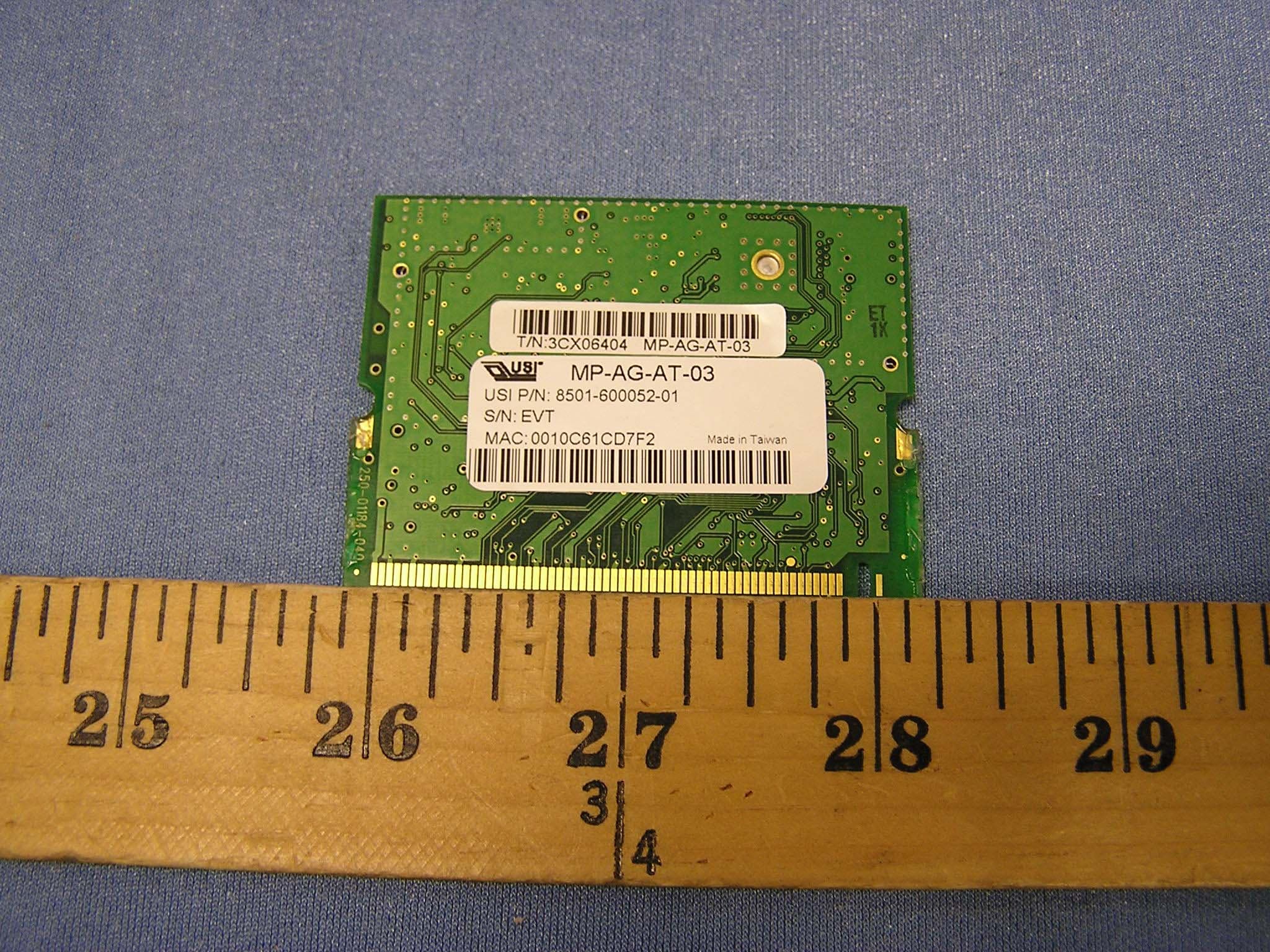
May 09, 2004802.11 a/b/g Mini-PCI Card
Equipment Class
DTS - Digital Transmission System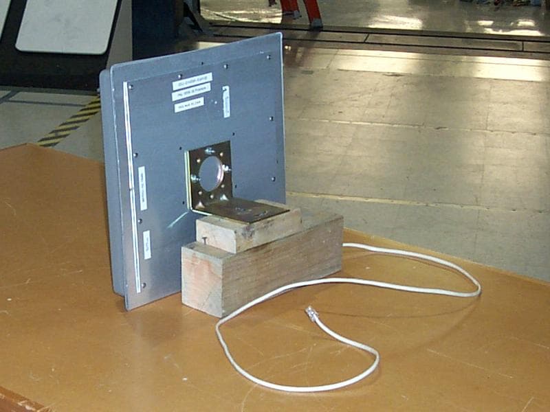
Q7O-0003
Feb 25, 2004802.11 Wireless Bridge
Equipment Class
DTS - Digital Transmission System