Q98GTX100Handy Terminal
Welcat, Inc.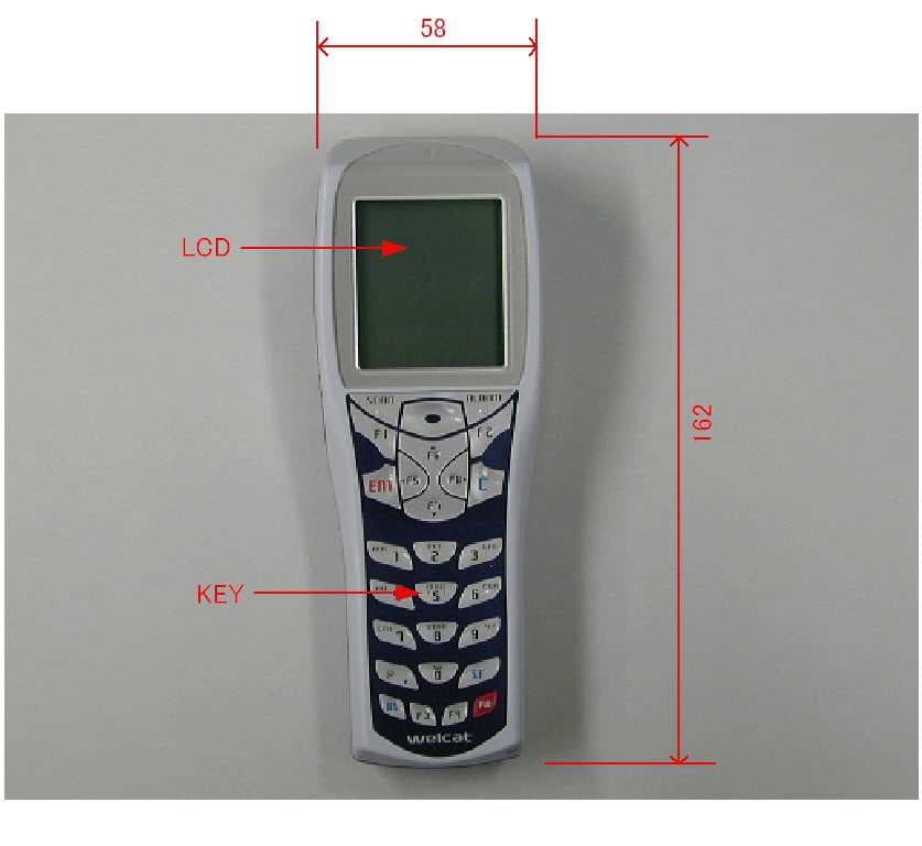
Click to zoom
Application Details
- Equipment Class
- DTS - Digital Transmission System
- Date of Grant
- Oct 23, 2007
- Application Purpose
- Original Equipment
- Date of Application
- Oct 23, 2007
- Equipment Note
- Handy Terminal
- Frequency Range
- 2412.00000000 - 2462.00000000
- Company
- Welcat, Inc.
- Country
- Japan
Documents & Files
Document Text
Text extracted from the exhibit documents filed with the FCC. Open a document above to read the original.
Users Manual
GTX-100 Õóåò§ó Íáîõáì ÇÔر°° ×éòåìåóó Èáîäù Ôåòíéîáì Èáòä÷áòå ̄ÓùóôåíÍåîõ i China Regulations This product is based on a Chinese SRRC rule. 1.Do not change frequency without permission, and increase the transmission of a message output.(include the installation of a high frequency amplifier out of a rule) 2.For the Occupied, do not give the interference that is harmful to the other legal radio broadcasting stations. When harmful interference occurred, stop use promptly, and reopen after removing interference. 3.When using low power wireless telegraphy facilities, bear the interference from the other legal radio broadcasting stations, or interfered with industry, science, radiation of medical facilities. 4.Do not use it in the vicinity of an airport and an airport. ii Trademarks -Microsoft, Windows, and Visual Basic are the U.S. Microsoft Corporation's registered trade- marks or the trademarks in the U.S. or other countries. -Bluetooth is the registered trademark of Bluetooth SIG, Inc. and Welcat, Inc is using it based on the license. -The program "UBQ-WLAN" developed by Canon i-tech,Inc. is equipped in this product. "UBQ-WLAN" is the trademark of Canon i-tech,Inc. -The decoder of MPEG Layer-3 audio is equipped in this product. -The decoding technology of MP3 is used based on the license from Fraunhofer IIS and Thomson. -The bit-mapped font developed by Ricoh Company,Ltd. is equipped in this product. -The copyrights of pictures, sound and tools included in each manual and each materials col- lection belong to Welcat, Inc. -The pictures, sound and tools included in each manual and each materials collection cannot use and reproduce any part or all of them without the express consent of Welcat, Inc. -The products and corporate names which are described in addition are the registered marks or brand of each enterprise. iii SAFETY PRECAUTIONS ・ Be sure to read these precautions before using this product in order to insure safe operation of the equipment. ・ Keep this User's Manual on hand for future reference whenever you may need it. Strict observance of these warning and caution indications are MUST for preventing accidents which could result in bodily injury and substantial property damage. Make sure you fully un- derstand all definitions of these terms and related symbols given below, before you proceed to the text itself. Danger This symbol indicates an item that can result in death or serious personal injury if ignored and emergency of warning when dangerously generated is high. Warning This symbol indicates an item that can result in death or serious personal injury if ignored. Caution This symbol indicates an item that can result in serious personal injury or material damage if ignored. Meaning of Symbols A diagonal line through a circle indicates something you should not do A black circle indicates something you must do. A triangle inside indicates something you should be careful about. iv Observe strictly Observe the display of the danger that the manufacturer of the personal com- puter and peripherals used is directing and warning and attention strictly when you use the product. About GTX-100, Battery pack(GTB-1) Danger Only use the specified our peripherals. Peripherals for GTX-100: - Battery pack (GTB-1) - Single charger (GTC-1) option - Multi charger (GTC-2) option Do not place or use the products in the hot places such as a fire side, a stove side, under the burning sun, etc. Doing so could cause battery –rupture or leakage of battery fluid and resulting in a fire, burn, bodily injury, or serious damage to property. Do not place products in a microwave oven and a high-pressure container, etc. Doing so could cause battery –rupture or leakage of battery fluid and resulting in a fire, burn, bodily injury, or serious damage to property. Do not heat products, nor put into fire . Doing so could cause battery –rupture or leakage of battery fluid and resulting in a fire, burn, bodily injury, or serious damage to property. Do not stare into laser beam. Do not aim the laser at a person’s eye. The laser beam emitted through the reading window is harmful to the eyes. v Warning Stop the charge, when the charge is not completed, even if it exceeds prede- termined charge time. Doing so could cause battery –rupture or leakage of battery fluid and resulting in a fire, burn, bodily injury, or serious damage to property. Do not place or use prod- ucts in high humid or dusty areas. Doing so could cause battery –rupture or leakage of battery fluid and resulting in a fire, burn, bodily injury, or serious damage to property. When heating, smoking, a nasty smell, etc. occur, turn off the power supply and remove the battery. When it continues using it, it will become the cause of generation of heat and firing. In a battery cartridge, it also becomes the cause of a liquid spill and a burst further. Do not attempt disassemble or modify products. Doing so could cause battery –rupture or leakage of battery fluid and resulting in a fire, burn, bodily injury, or serious damage to property. Prevent from touching a part of your body, such as a hand and a finger to the terminals of a battery, the battery contacts / charge contacts of a main body, and the external aerial connection terminal. It may become the cause of an electric shock, injury, failure, and malfunction. Do not bring close to chemicals. Do not use and keep it near chemicals or in the place which chemicals touch. It becomes accidents, such as an electric shock and a fire, or the cause of failure. Do not short-circuit or sol- der neither the battery ter- minals, nor the battery contacts / charge contacts of a main body. Doing so could cause battery –rupture or leakage of battery fluid and resulting in a fire, burn, bodily injury, or serious damage to property. Do not connect reversely the positive and negative polarity terminals of a bat- tery, and do not charge it in that condition. Doing so could cause battery –rupture or leakage of battery fluid a…
Text truncated - open the document above for the full version.
External Photos
Key LCD Key Key Li-ion Battery
Internal Photos
WLAN Module WLAN Board Vibrator Board Main Board WLAN Module Scanner Module WLAN Antenna LCD Module WLAN Antenna WLAN Antenna Main Board WLAN Board Bluetooth Module Bluetooth Antenna Bluetooth Antenna Bluetooth Module LCD Module Scanner Module WLAN Module WLAN Antenna Vibrator Board
RF Exposure Info
Attachment 1 – System Validation Plots JAPAN QUALITY ASSURANCE ORGANIZATION Date/Time: 2007/10/01 12:59:59 Test Laboratory: JAPAN QUALITY ASSURANCE ORGANIZATION System Validation DUT: Dipole 2450 MHz; Type: D2450V2; Serial: 714 Communication System: CW; Frequency: 2450 MHz;Duty Cycle: 1:1 Medium: M2450 Medium parameters used: f = 2450 MHz; σ = 2.02 mho/m; ε r = 51.4; ρ = 1000 kg/m 3 Phantom section: Flat Section Measurement Standard: DASY4 (High Precision Assessment) DASY4 Configuration: zProbe: ET3DV6 - SN1679; ConvF(4.29, 4.29, 4.29); Calibrated: 2006/11/16 zSensor-Surface: 4mm (Mechanical And Optical Surface Detection) zElectronics: DAE3 Sn508; Calibrated: 2006/11/09 zPhantom: SAM 1200; Type: QD 000 P40 CA; Serial: 1200 zMeasurement SW: DASY4, V4.7 Build 44; Postprocessing SW: SEMCAD, V1.8 Build 171 Antenna Input Power 250 mW/Area Scan (5x5x1): Measurement grid: dx=20mm, dy=20mm Maximum value of SAR (measured) = 14.8 mW/g Antenna Input Power 250 mW/Zoom Scan (5x5x7)/Cube 0: Measurement grid: dx=8mm, dy=8mm, dz=5mm Reference Value = 89.4 V/m; Power Drift = -0.024 dB Peak SAR (extrapolated) = 31.3 W/kg SAR(1 g) = 13.3 mW/g; SAR(10 g) = 6.04 mW/g Maximum value of SAR (measured) = 14.6 mW/g 0 dB = 14.6mW/g JAPAN QUALITY ASSURANCE ORGANIZATION
RF Exposure Info
Attachment 2 – SAR Test Plots JAPAN QUALITY ASSURANCE ORGANIZATION Date/Time: 2007/10/01 13:44:05 Test Laboratory: JAPAN QUALITY ASSURANCE ORGANIZATION 802.11b 6ch (2437MHz) - Back DUT: Handy Terminal; Type: GTX-100; Serial: WBG0701075 Communication System: WLAN; Frequency: 2437 MHz;Duty Cycle: 1:1 Medium: M2450 Medium parameters used: f = 2437 MHz; σ = 2.02 mho/m; ε r = 51.4; ρ = 1000 kg/m 3 Phantom section: Flat Section Measurement Standard: DASY4 (High Precision Assessment) DASY4 Configuration: zProbe: ET3DV6 - SN1679; ConvF(4.29, 4.29, 4.29); Calibrated: 2006/11/16 zSensor-Surface: 4mm (Mechanical And Optical Surface Detection) zElectronics: DAE3 Sn508; Calibrated: 2006/11/09 zPhantom: SAM 1200; Type: QD 000 P40 CA; Serial: 1200 zMeasurement SW: DASY4, V4.7 Build 44; Postprocessing SW: SEMCAD, V1.8 Build 171 Body-worn/Area Scan (6x9x1): Measurement grid: dx=15mm, dy=15mm Maximum value of SAR (measured) = 0.076 mW/g Body-worn/Zoom Scan (5x5x7)/Cube 0: Measurement grid: dx=8mm, dy=8mm, dz=5mm Reference Value = 5.84 V/m; Power Drift = -0.088 dB Peak SAR (extrapolated) = 0.167 W/kg SAR(1 g) = 0.079 mW/g; SAR(10 g) = 0.043 mW/g Maximum value of SAR (measured) = 0.083 mW/g 0 dB = 0.083mW/g JAPAN QUALITY ASSURANCE ORGANIZATION Date/Time: 2007/10/01 14:01:49 Test Laboratory: JAPAN QUALITY ASSURANCE ORGANIZATION 802.11g 6ch (2437MHz) - Back DUT: Handy Terminal; Type: GTX-100; Serial: WBG0701075 Communication System: WLAN; Frequency: 2437 MHz;Duty Cycle: 1:1 Medium: M2450 Medium parameters used: f = 2437 MHz; σ = 2.02 mho/m; ε r = 51.4; ρ = 1000 kg/m 3 Phantom section: Flat Section Measurement Standard: DASY4 (High Precision Assessment) DASY4 Configuration: zProbe: ET3DV6 - SN1679; ConvF(4.29, 4.29, 4.29); Calibrated: 2006/11/16 zSensor-Surface: 4mm (Mechanical And Optical Surface Detection) zElectronics: DAE3 Sn508; Calibrated: 2006/11/09 zPhantom: SAM 1200; Type: QD 000 P40 CA; Serial: 1200 zMeasurement SW: DASY4, V4.7 Build 44; Postprocessing SW: SEMCAD, V1.8 Build 171 Body-worn/Area Scan (6x9x1): Measurement grid: dx=15mm, dy=15mm Maximum value of SAR (measured) = 0.037 mW/g Body-worn/Zoom Scan (5x5x7)/Cube 0: Measurement grid: dx=8mm, dy=8mm, dz=5mm Reference Value = 4.16 V/m; Power Drift = -0.113 dB Peak SAR (extrapolated) = 0.074 W/kg SAR(1 g) = 0.037 mW/g; SAR(10 g) = 0.021 mW/g Maximum value of SAR (measured) = 0.039 mW/g 0 dB = 0.039mW/g JAPAN QUALITY ASSURANCE ORGANIZATION Date/Time: 2007/10/01 15:02:29 Test Laboratory: JAPAN QUALITY ASSURANCE ORGANIZATION 802.11b 1ch (2412MHz) - Front DUT: Handy Terminal; Type: GTX-100; Serial: WBG0701075 Communication System: WLAN; Frequency: 2412 MHz;Duty Cycle: 1:1 Medium: M2450 Medium parameters used: f = 2412 MHz; σ = 2.02 mho/m; ε r = 51.4; ρ = 1000 kg/m 3 Phantom section: Flat Section Measurement Standard: DASY4 (High Precision Assessment) DASY4 Configuration: zProbe: ET3DV6 - SN1679; ConvF(4.29, 4.29, 4.29); Calibrated: 2006/11/16 zSensor-Surface: 4mm (Mechanical And Optical Surface Detection) zElectronics: DAE3 Sn508; Calibrated: 2006/11/09 zPhantom: SAM 1200; Type: QD 000 P40 CA; Serial: 1200 zMeasurement SW: DASY4, V4.7 Build 44; Postprocessing SW: SEMCAD, V1.8 Build 171 Body-worn/Area Scan (6x9x1): Measurement grid: dx=15mm, dy=15mm Maximum value of SAR (measured) = 0.109 mW/g Body-worn/Zoom Scan (5x5x7)/Cube 0: Measurement grid: dx=8mm, dy=8mm, dz=5mm Reference Value = 5.92 V/m; Power Drift = -0.126 dB Peak SAR (extrapolated) = 0.332 W/kg SAR(1 g) = 0.124 mW/g; SAR(10 g) = 0.055 mW/g Maximum value of SAR (measured) = 0.125 mW/g 0 dB = 0.125mW/g JAPAN QUALITY ASSURANCE ORGANIZATION Date/Time: 2007/10/01 14:16:42 Test Laboratory: JAPAN QUALITY ASSURANCE ORGANIZATION 802.11b 6ch (2437MHz) - Front DUT: Handy Terminal; Type: GTX-100; Serial: WBG0701075 Communication System: WLAN; Frequency: 2437 MHz;Duty Cycle: 1:1 Medium: M2450 Medium parameters used: f = 2437 MHz; σ = 2.02 mho/m; ε r = 51.4; ρ = 1000 kg/m 3 Phantom section: Flat Section Measurement Standard: DASY4 (High Precision Assessment) DASY4 Configuration: zProbe: ET3DV6 - SN1679; ConvF(4.29, 4.29, 4.29); Calibrated: 2006/11/16 zSensor-Surface: 4mm (Mechanical And Optical Surface Detection) zElectronics: DAE3 Sn508; Calibrated: 2006/11/09 zPhantom: SAM 1200; Type: QD 000 P40 CA; Serial: 1200 zMeasurement SW: DASY4, V4.7 Build 44; Postprocessing SW: SEMCAD, V1.8 Build 171 Body-worn/Area Scan (6x9x1): Measurement grid: dx=15mm, dy=15mm Maximum value of SAR (measured) = 0.128 mW/g Body-worn/Zoom Scan (5x5x7)/Cube 0: Measurement grid: dx=8mm, dy=8mm, dz=5mm Reference Value = 5.40 V/m; Power Drift = -0.098 dB Peak SAR (extrapolated) = 0.484 W/kg SAR(1 g) = 0.183 mW/g; SAR(10 g) = 0.081 mW/g Maximum value of SAR (measured) = 0.188 mW/g 0 dB = 0.188mW/g JAPAN QUALITY ASSURANCE ORGANIZATION Date/Time: 2007/10/01 15:18:38 Test Laboratory: JAPAN QUALITY ASSURANCE ORGANIZATION 802.11b 11ch (2462MHz) - Front DUT: Handy Terminal; Type: GTX-100; Serial: WBG0701075 Communication System: WLAN; Frequency: 2462 MHz;Duty Cycle: 1:1 Medium: M2450 Medium parameters used: f = 2462 MHz; σ = 2.02 mho/m; ε r = 51.4; ρ = 1000 kg/m 3 Phantom section: Flat Section Measurement Standard: DASY4 (High Precision Assessment) DASY4 Configuration: zProbe: ET3DV6 - SN1679; ConvF(4.29, 4.29, 4.29); Calibrated: 2006/11/16 zSensor-Surface: 4mm (Mechanical And Optical Surface Detection) zElectronics: DAE3 Sn508; Calibrated: 2006/11/09 zPhantom: SAM 1200; Type: QD 000 P40 CA; Serial: 1200 zMeasurement SW: DASY4, V4.7 Build 44; Postprocessing SW: SEMCAD, V1.8 Build 171 Body-worn/Area Scan (6x9x1): Measurement grid: dx=15mm, dy=15mm Maximum value of SAR (measured) = 0.321 mW/g Body-worn/Zoom Scan (5x5x7)/Cube 0: Measurement grid: dx=8mm, dy=8mm, dz=5mm Reference Value = 10.2 V/m; Power Drift = -0.098 dB Peak SAR (extrapolated) = 0.895 W/kg SAR(1 g) = 0.341 mW/g; SAR(10 g) = 0.150 mW/g Maximum value of SAR (measured) = 0.347 mW/g 0 dB = 0.347mW/g JAPAN QUALITY ASSURANCE ORGANIZATION Date/Time: 2007/10/01 15:32:54 Test Laborato…
Text truncated - open the document above for the full version.
RF Exposure Info
JAPAN QUALITY ASSURANCE ORGANIZATION Attachment 3 – Dosimetric E-Field Probe – ET3DV6, S/N: 1679 Calibration Data
RF Exposure Info
JAPAN QUALITY ASSURANCE ORGANIZATION Attachment 4 – System Validation Dipole – D2450V2, S/N: 714 Calibration Data
RF Exposure Info
Page 1 of 21 Technical document No. 23763-0601 JQA File No. : KL80070323 Issue Date : October 3, 2007 TEST REPORT (SAR EVALUATION) APPLICANT : Welcat Inc. ADDRESS : 4-12-8 Higashi-Shinagawa, Shinagawa Seaside East Tower 6F, Shinagawa-ku 140-0002 Tokyo, Japan PRODUCTS : Handy Terminal MODEL NO. : GTX-100 SERIAL NO. : WBG0701075 FCC ID : Q98GTX100 TEST STANDARD : FCC/OET Bulletin 65 Supplement C (Edition 01-01) TESTING LOCATION : Japan Quality Assurance Organization KITA-KANSAI Testing Center 1-7-7, Ishimaru, Minoh-shi, Osaka 562-0027, Japan TEST RESULTS : Passed DATE OF TEST : October 1, 2007 This report must not used by the client to claim product endorsement by NVLAP or Yuichi Fukumoto NIST or any agency of the U.S. Government. Manager Japan Quality Assurance Organization KITA-KANSAI Testing Center Testing Dept. EMC Division NVLAP LAB CODE 200191-0 1-7-7, Ishimaru, Minoh-shi, Osaka 562-0027, Japan ● The measurement values stated in Test Report was made with traceable to National Institute of Advanced Industrial Science and Technology (AIST) of Japan, National Institute of Information and Communications Technology (NICT) of Japan , and Laboratory for EMF and Microwave Electronics at the Swiss Federal Institute of Technology (ETH) in Zürich, Switzerland. ● The applicable standard, testing condition and testing method which were used for the tests are based on the request of the applicant. ● The test results presented in this report relate only to the offered test sample. ● The contents of this test report cannot be used for the purposes, such as advertisement for consumers. ● This test report shall not be reproduced except in full without the written approval of JQA. JAPAN QUALITY ASSURANCE ORGANIZATION JQA File No. : KL80070323 Issue Date : October 3, 2007 Model No. : GTX-100 FCC ID : Q98GTX100 Standard : FCC/OET Bulletin 65 Supplement C (Edition 01-01) Page 2 of 21 Technical document No. 23763-0601 TABLE OF CONTENTS Page Documentation ................................................................................................................................................. 3 1 Test Regulation.....................................................................................................................................3 2 Test Location.........................................................................................................................................3 3 Recognition of Test Laboratory............................................................................................................3 4 Description of the Equipment Under Test..........................................................................................4 5 Measurement System Diagram............................................................................................................5 6 System Components..............................................................................................................................6 7 Measurement Process...........................................................................................................................8 8 Measurement Uncertainties.................................................................................................................9 9 Equipment Under Test Modification.................................................................................................10 10 Responsible Party................................................................................................................................10 11 Deviation from Standard....................................................................................................................10 12 Test Results.........................................................................................................................................11 13 Summary..............................................................................................................................................12 14 Test Arrangement...............................................................................................................................13 15 Equipment Under Test Tune-Up Procedures....................................................................................15 Appendix A: Test Data ................................................................................................................................... 16 A.1 Tissue Verification..............................................................................................................................16 A.2 System Validation...............................................................................................................................17 A.3 SAR Measurement Data.....................................................................................................................18 Appendix B: Test Instruments....................................................................................................................... 20 Appendix C: Attachments .............................................................................................................................. 21 DEFINITIONS FOR ABBREVIATION AND SYMBOLS USED IN THIS TEST REPORT “EUT” means Equipment Under the Test. “N/A” means that Not Applicable. “N/T” means that Not Tested. - indicates that the listed condition, standard or equipment is applicable for this report. - indicates that the listed condition, standard or equipment is not applicable for this report. JAPAN QUALITY ASSURANCE ORGANIZATION JQA File No. : KL80070323 Issue Date : October 3, 2007 Model No. : GTX-100 FCC ID : Q98GTX100 Standard : FCC/OET Bulletin 65 Supplement C (Edition 01-01) Page 3 of 21 Technical document No. 23763-0601 Documentation 1 Test Regulation Applied Standard : FCC/OET Bulletin 65 Supplement C (Edition 01-01) Evaluating Compliance with FCC Guidelines for Human Exposure to Radio- frequency Electromagnetic Fields Addi…
Text truncated - open the document above for the full version.
Test Report
Page 2 of 54 Test Report No. E64127-1 Cosmos Corporation Cosmos CorporationCosmos Corporation Cosmos Corporation COSMOS COSMOSCOSMOS COSMOS List ListList List of Contents of Contents of Contents of Contents Page PagePage Page 1. Description of Equipment Under Test .............................................................................................. 4 1.1 Product Description ...................................................................................................................... 4 1.2 Antenna Description..................................................................................................................... 4 1.3 Accompanied Peripherals Description ........................................................................................4 2. General Information ............................................................................................................................. 5 2.1 Test Methodology .......................................................................................................................... 5 2.2 Test Facility................................................................................................................................... 5 2.3 Traceability ................................................................................................................................... 5 3. Summary of Test Results ..................................................................................................................... 5 4. Test Configuration ................................................................................................................................ 6 4.1 15. 207 AC Power Conducted Emission in Shield Room ......................................................... 6 4.2 15. 247(c) Transmitter Radiated Emissions and Band Edge (Radiated) in 3m Anechoic Chamber ................................................................................................................................................. 6 4.3 All Other Test Items (Except Maximum Peak Output Power) ............................................... 7 4.4 Maximum Peak Output Power ..................................................................................................7 4.5 Test Mode .................................................................................................................................... 7 5. Measurement Result............................................................................................................................. 8 5.1 15. 207 AC Power Conducted Emission .................................................................................... 8 5.1.1 Setting Remarks.................................................................................................................. 8 5.1.2 Minimum Standard............................................................................................................. 8 5.1.3 Result ................................................................................................................................... 8 5.1.4 Measured Data .................................................................................................................... 9 5.2 15. 247(a)(2) Spectrum Bandwidth of Direct Sequence ......................................................... 11 Spread Spectrum System.................................................................................................................... 11 5.2.1 Setting Remarks................................................................................................................ 11 5.2.2 Minimum Standard........................................................................................................... 11 5.2.3 Result ................................................................................................................................. 11 5.2.4 Measured Data .................................................................................................................. 11 5.3 15. 247(b) Maximum Peak Output Power .............................................................................. 12 5.3.1 Setting Remarks................................................................................................................ 12 5.3.2 Minimum Standard........................................................................................................... 12 5.3.3 Result ................................................................................................................................. 12 5.3.4 Measured Data .................................................................................................................. 13 5.4 15. 247(c) Transmitter Radiated Emissions (Conducted)...................................................... 14 5.4.1 Setting Remarks................................................................................................................ 14 5.4.2 Minimum Standard........................................................................................................... 14 5.4.3 Result ................................................................................................................................. 14 5.4.4 Measured Data (No emission exceeding the 20dB limit was found) ............................. 15 Page 3 of 54 Test Report No. E64127-1 Cosmos Corporation Cosmos CorporationCosmos Corporation Cosmos Corporation COSMOS COSMOSCOSMOS COSMOS 5.5 15. 247(c) Transmitter Radiated Emissions (Radiated) ........................................................ 17 5.5.1 Setting Remarks................................................................................................................ 17 5.5.2 Minimum Standard........................................................................................................... 18 5.5.3 Result ..............................................................................…
Text truncated - open the document above for the full version.
Test Setup Photos
Page 47 of 52 Test Report No. E64127-2 Cosmos Corporation COSMOS 6. Photos 6.1 Setup Photo (Conducted Emission) Front View Side View Page 48 of 52 Test Report No. E64127-2 Cosmos Corporation COSMOS 6.2 Setup Photo (Radiated Emission) Front View (Axis A) Rear View (Axis A) Page 49 of 52 Test Report No. E64127-2 Cosmos Corporation COSMOS 6.2 Setup Photo (Radiated Emission) Front View (Axis B) Rear View (Axis B) Page 50 of 52 Test Report No. E64127-2 Cosmos Corporation COSMOS 6.2 Setup Photo (Radiated Emission) Front View (Axis C) Rear View (Axis C)
Contact Information
Applicant
Masakiyo Yamazaki(R&D Dept. Chief Clerk)
Technical Contact
Cosmos CorporationDavid Watanuki
[email protected]81-596-63-0707
2-3571 Ohnogi, Watarai-cho, Watarai-gun · Mie · Japan
Non-Technical Contact
Cosmos CorporationDavid Watanuki
[email protected]81-596-63-0707
Test Firm
Cosmos CorporationEiji Asano
Technical Specifications
| # | Rule Parts | Frequency Range | Power Output |
|---|---|---|---|
| 1 | 15C | 2.41 GHz - 2.46 GHz | 40.00 mW |
Other Applications from Welcat, Inc.
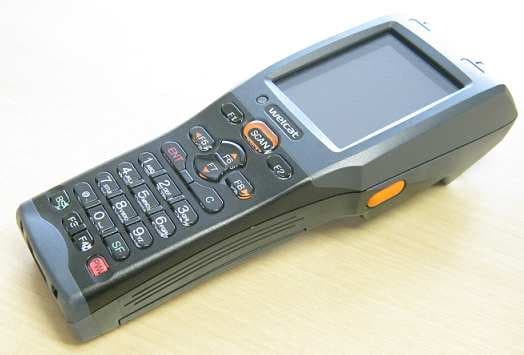
Q98GTX221G
Sep 23, 2012Wireless 2D-code Handy Terminal
Equipment Class
DSS - Part 15 Spread Spectrum Transmitter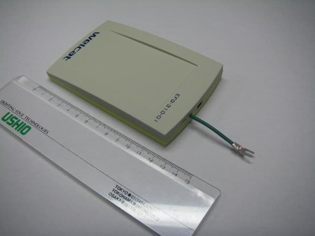
Q98CSH07334
Feb 26, 2008RFID IC Card/IC Tag Reader/Writer
Equipment Class
DXX - Part 15 Low Power Communication Device Transmitter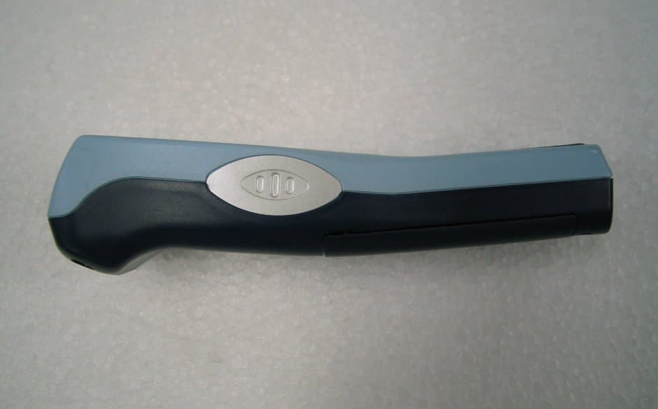
Q98XIT100BW
Dec 19, 2005Barcode Reader with 802.11b&Bluetooth Transmitters
Equipment Class
DTS - Digital Transmission System