Q98XIT100BWBarcode Reader with 802.11b&Bluetooth Transmitters
Welcat, Inc.
Click to zoom
Application Details
- Equipment Class
- DTS - Digital Transmission System
- Date of Grant
- Dec 19, 2005
- Application Purpose
- Original Equipment
- Date of Application
- Dec 19, 2005
- Equipment Note
- Barcode Reader with 802.11b&Bluetooth Transmitters
- Frequency Range
- 2412.00000000 - 2462.00000000
- Company
- Welcat, Inc.
- Country
- Japan
Documents & Files
Document Text
Text extracted from the exhibit documents filed with the FCC. Open a document above to read the original.
Users Manual
i Copyright ©2005 Welcat Inc. All rights reserved. This document may not be reproduced whole or in part without prior consent from the publisher. Specifications are subject to change without prior notice. All products and company names mentioned in this manual are the trade- marks or registered trademarks of their respective owners. ii SAFETY PRECAUTIONS ・ Be sure to read these precautions before using this product in order to insure safe operation of the equipment. ・ Keep this User's Manual on hand for future reference whenever you may need it. Strict observance of these warning and caution indications are MUST for preventing accidents, which could result in bodily injury and substantial property damage. Make sure you fully un- derstand all definitions of these terms and related symbols given below, before you proceed to the text itself. Warning This symbol indicates an item that can result in death or serious personal injury if ignored. Caution This symbol indicates an item that can result in serious personal injury or material damage if ignored. Meaning of Symbols A diagonal line through a circle indicates something you should not do. A black circle indicates something you must do. A triangle inside indicates something you should be careful about. iii WARNING Only use the specified bat- tery pack (HBC-51). Using a different type of battery pack could cause damage to equipment, battery –rupture or leakage of battery fluid and re- sulting in a fire, burn, bodily injury, or serious damage to property. Only use the specified charger (QC-001, QC-002) for charging the battery pack. Using a different type of charger could cause battery –rupture or leakage of battery fluid and re- sulting in a fire, burn, bodily injury, or serious damage to property. Do not heat the battery pack, nor put into fire or water. Doing so could cause battery –rupture or leakage of battery fluid and resulting in a fire, burn, bodily injury, or serious damage to property. Do not attempt disassemble or modify the battery pack. Doing so could cause battery –rupture or leakage of battery fluid and resulting in a fire, burn, bodily injury, or serious damage to property. Do not carry or store the battery pack together with metallic object such as ballpoint pen, necklaces, coins, hairpins, etc. Doing so could short-circuit the terminal pins, causing the bat- teries to rupture the battery fluid to leak, resulting in a fire, burn, and bodily injury. Do not use the battery if leakage, change of color or shape, or other abnormali- ties occur. Doing so could cause fire, burn, bodily injury, or serious damage to property. If it brings close to fire, this cause ignition in leak- age of battery fluid. Avoid dropping the battery pack or letting it undergo any shock or impact. Doing so could cause the bat- teries to break, generate heat, rupture or burn. Do not charge the battery pack where an y inflammable gases may be emitted. Doing so could cause battery –rupture or leakage of battery fluid and resulting in a fire, burn, bodily injury, or serious damage to property. iv WARNING Do not place or charge the battery in the hot places such as a fireside, a stove side, under the burning sun, etc. Doing so could cause battery –rupture or leakage of battery fluid and resulting in a fire, burn, bodily injury, or serious damage to property. If battery fluid gets in your eyes, wash it out with clean water and contact a physi- cian immediately. If it is left, there is fear of loss of eyesight. If battery fluid gets on your skin, or clothes, wash it off with clean water. If it is left, there is fear of dam- age of skin. Do not attempt disassemble or modify the terminal. Doing so could cause failure, excessive heat, fire, or electrical shock. Be careful not to hook a strap when carrying the terminal. If strap is caught in an obstacle, it could cause injury or accident. Do not stare into laser beam. Do not aim the laser at a person’s eye. The laser beam emitted through the reading window is harmful to the eyes. v CAUTION Do not place or use the terminal in the hot places such as a fireside, a stove side, under the burning sun, etc. Doing so could cause fire, modification of a case or equipment trouble. Do not place or use the terminal in high humid or dusty areas. If moisture ore dust will get into the terminal, resulting in failure, fire or electrical shock. Do not soak in water. If water will gets into the ter- minal, resulting in failure, fire or electrical shock. Do not drop the terminal or subject it to strong impact or vibrations. This could cause malfunction or failure. vi Laser Safety This product using the laser complies with US 21CFR1040.10. This equipment is certified as a Class 2 laser product under the U.S. Department of Health and Human Services (DHHS) Radiation Performance Standard according to the Radiation Control for Health and Safety Act of 1968. This means that the equipment does not produce hazardous laser radiation. FDA Regulations U.S. Food and Drug Administration (FDA) have implemented regulations for laser products manufactured on and after August 2, 1976. Compliance is mandatory for products marketed in the United States. The labels on the product indicate compliance with the FDA regulations and must be attached to laser products marketed in the United States. Caution: Do not look into the laser beam source through the reading window or point the reading window towards the eyes. The laser beam emitted through the reading window is harmful to the eyes. Use of controls, adjustments or performance of procedures other than those specified in this manual may result in hazardous invisible radiation exposure. Class 2 laser scanners use a low power, visible light diode. As with any very bright light source, such as the sun, the user should avoid staring directly into the light beam. Momentary exposure to a Class 2 laser is not known to be harmful. vii (INSIDE) XIT-100-BW Labels CAUTION Wirless Hand-held Terminal XIT-100-BW FCC …
Text truncated - open the document above for the full version.
Users Manual
3-10 Network Menu 3-33ġ ³±° Îåô÷ïòë Íåîõ Network related setting such as TCP/IP. 1. From the System menu, select "3:Network". Select the item to setup. ˁ ÔÃÐ ̄ÉÐ ˁ ÄÈÃÐ ˁ ÆÔÐ ˁ ÄÎÓ ˁ ÓÎÍÐ ³±°± ÔÃÐ ̄ÉÐ Set an IP address and other details for TCP/IP communications. Automatic setup is possible when the DHCP function is enabled. 1. From the Network, select "1:TCP/IP". Current setting contents are displayed. Select the item to setup. 2. Input the address. Input the number from 000 to 255 to the field segmented by the period (exampleȇ192.168.254.254). * The Display is an example of "IP address". "NetMask" and "Gateway" is operated in the same way. Chapter 3 System menu 3-34ġ ˁÉÐ áääòåóó Set the IP address assigned by the network administrator. Set a unique IP address to each of the XIT-100-BW terminals connected to the same network. ˁÎåôÍáóë ̈Óõâîåô íáóë© Set the subnet mask assigned by the network administrator. Since a subnet mask specifies which network you belong to, it should set up along with the IP address. ˁÇáôå÷áù ̈Äåæáõìô çáôå÷áù© Set the address of the default gateway. Setup is required when connecting to a different network through a router. ˁ ÍÔÕ The maximum length of IP packet. 1500 octets (bytes) is common for Ethernet. In such cases as being used over the routers, this value should be modified according to the communication me- dia. Please ask the network administrator about the value settings for different items. ×èåî ôèå óôáôõó ïæ ôèå ÉÐ áääòåóó éó Û°°°®°°°®°°°®°°°Ý¬ôèå ×ÌÁÎ ãïííõîéãáôéïî éó õîáâìå ôï âå åøåãõôåä® Ðìåáóå áóë ôèå îåô÷ïòë áäíéîéóôòáôïò áâïõô ôèå öáìõå óåôôéîçó æïò äéææåòåîô éôåíó® Æòïí ôèå ¢Óôáòôõð ôùðå¢ ïæ ÄÈÃÐ óåôôéîç ̈Ю³³μ©¬ éî ãáóå åéôèåò ¢Áððìéãáôéïî âïïô¢ ïò ¢Óùóôåí íåîõ âïïô¢ éó óåìåãôåä¬ ôèå öáìõå åøãåðô æïò ÍÔÕ ãáî ïîìù âå ãïîæéòíåä âõô õîáâìå ôï âå íïäéæéåä® ³±°² ÄÈÃÐ Set the DHCP client function that is used for automatic setup of TCP/IP and various set items. 1. From the Network menu, select "2:DHCP." Select the item to setup. ˁ Óôáòôõð ôùðå ˁ Õðäáôå ðòïôåãô ˁ Óåòöåò ðïòô 3-10 Network Menu 3-35ġ ǪÓôáòôõð ôùðå 1. Select the item to setup. ˁ Äéóáâìåä ̈Æáãôïòù óåôõð© DHCP is not executed when the terminal started up. ˁ Áððìéãáôéïî âïïô DHCP is executed before the application is executed. The application file is selected from <System menu>[1:System], and then[2:Auto execute], DHCP function is executed before application , after the terminal started up. In addition, when the application is started up from <File menu>, DHCP is not executed. ˁ Óùóôåí íåîõ âïïô DHCP is executed before System menu is started up. The Sys- tem menu is selected from <System menu>[1:System], and then[1:Auto execute], DHCP function is executed before Sys- tem menu is started up , after the terminal started up. ǪÕðäáôå ðòïôåãô Following information unique to the terminal is setup so as not to be modified, before executing DHCP function. ˁ ÉÐ áääòåóó ˁ ÎåôÍáóë ˁ Çáôå÷áù ˁ ÉÄ Éî ôèå ãáóå ÷èåî ôèå ãèåãë éó áððìéåä ôï ÉÐ áääòåóó ̈ÉÐ áääòåóó õð äáôå éó ðòïèéâéôå䩬 ôèå ÉÐ áääòåóó¬ ÷èéãè èáó óåô õð áô ôèå ôåòíéîáì¬ éó îïô íïäéæéåä® Âå óõòå ôï õóå ãïîæéòíéîç ôèáô ôèå ôèåòå éó îï èïóô ÷éôè ôèå óáíå ÉÐ áääòåóó ïî ôèå Îåô÷ïòë® ǪÓåòöåò ðïòô îõíâåò DHCP server port is setup (Factory setupȇ08067). If you do not execute the automatic setup, which is unique to the XIT-100-BW, and want to use exist- ing server only to perform the assigning of IP address, the value is modified (the well known port is 67). Ôèå ðïòô îõíâåò ïæ ôèå ÄÈÃÐ óåòöåò ïæ ¢×åâÇìéäåòØ¢ Îåô÷ïòë íáîáçåò éó ° ̧°¶· áó äåæáõìô® Ôèéó éó ôï áöïéä á ãïíðåôéôéïî ÷éôè ïôèåò ÄÈÃÐ óåòöåòó ÷ïòëéîç éî ôèå óáíå îåô÷ïòë® ǪÅøåãõôå Press the key, and, DHCP is executed immediately, regardless of "Startup type"(P.3-35). Chapter 3 System menu 3-36ġ ³±°³ ÆÔÐ Set up for using the FTP client function, as described below. Automatic setup is possible when the DHCP func- tion is enabled. 1. From the Network, select "3:FTP". Select the item to setup. ˁ Óåòöåò áääòåóó ˁ Õóåò îáíå ˁ Ðáóó÷ïòä ˁ Áäöáîãåä ǪÓåòöåò áääòåóó Set up the host name for FTP server. 1. Select from either IP, or, URL. ˁ Áääòåóó The IP address setup at 2:IP" is set as FTP server. ˁ Îáíå The host specified at "3: host name" is set as FTP server. The host name can not contain the space character. ×èåî õóéîç ¢Îáí墬 ðìåáóå ðåòæïòí ôèå ÄÎÓ óåôõð ̈Ю³³¹©®¢ 3-10 Network Menu 3-37ġ ǪÕóåò îáíå Specify the FTP server login user name using up to 18 alphanumeric characters, and up- per-case/lower-case should be distinguished. 1. Input the User name. User name should not include the space. ǪÐáóó÷ïòä Specify the FTP server login password using up to 20 alphanumeric characters, and up- per-case/lower-case should be distinguished. 1. Input the Password. The Password is converted to a hidden character (*) and is displayed for security purpose. Password should not include the space. ǪÁäöáîãåä Chapter 3 System menu 3-38ġ ǴÓåòöåò ðïòô Specify FTP server control port number. The well-known port is 21. ǴÍïäå The default is Passive mode. If the FTP server does not support Passive mode, change it to the Active mode. Ôèåòå éó á æõîãôéïî ôï òåêåãô ôèå ãïîîåãôéïî æòïí ïõôóéäå ôèå Æéòå÷áìì ôï éîóéäå éî ôèå Æéòå÷áìì óåô õð® Éæ ôèéó æõîãôéïî éó åîáâìåä¬ ôèå ÆÔÐ ãïííõîéãáôéïî ãáîîïô âå ðåòæïòíåä éî ôèå Áãôéöå íïäå® Âù õóéîç Ðáóóéöå íïäå¬ ôèå ãïííõîéãáôéïî âåô÷ååî ôèå ÆÔÐ óåòöåò ïöåò ôèå Æéòå÷áìì® ǴÆïìäåò ˁÃõòòåîô /(root) In some FTP server, the User name folder is specified as root folder. /(user name) The folder in the root folder with the same as the user name of the FTP server is specified as the current folder. If FTP function (file transmission or reception) is executed without setting the user name, the error screen appears. /(Specified) The relative path setup at the "specified folder" which is to be explained later becomes the cur- rent folder. ˁÓðåãéæéåä When selected "/(Specified)" in the folder above, the character string setup here are added to the FTP method "CWD". As the setup character stri…
Text truncated - open the document above for the full version.
External Photos
XIT-100-BW External Photos Top Bottom Left side Right side Front Back
ID Label/Location Info
(INSIDE) XIT-100-BW Labels Product Label Serial Label This product complies with 21 CFR 1040.10. MANUFACTURED:NOV.2005 Welcat Inc. 1-17-12 ShinYokohama,Kohoku-ku,Yokohama, Kanagawa,JAPAN FDA Label This product complies with 21 CFR 1040.10. MANUFACTURED:NOV.2005 Welcat Inc. 1-17-12 ShinYokohama,Kohoku-ku,Yokohama, Kanagawa,JAPAN 11092750064 CAUTION Wirless Hand-held Terminal XIT-100-BW FCC ID:Q98XIT100BW IC:6206A-XIT100BW MADE IN JAPAN LASER LIGHT DO NOT STARE INTO BEAM 650nmLASER 1.0mW MAX OUTPU CLASS II LASER PRODUCT 11092750064 CAUTION Wirless Hand-held Terminal XIT-100-BW FCC ID:Q98XIT100BW IC:6206A-XIT100BW MADE IN JAPAN LASER LIGHT DO NOT STARE INTO BEAM 650nmLASER 1.0mW MAX OUTPU CLASS II LASER PRODUCT SER No.
Internal Photos
XIT-100-BW Internal Photos WLAN module WLAN antenna Bluetooth module Bluetooth antenna WLAN antenna
Internal Photos
External Photo Internal Photo
Operational Description
FOR AUTO ID SYSTEMS FCC ID:Q98XIT100BW Dimensions SPECIFICATIONS Parameter VSWR Impedance Gain Test conditionsRating 3.0:1 Maximum (2450MHz) 50 Ohms An antenna is attached on the specified position of a handheld terminal, and is measured. 2.14dBi Maximum Antenna typeModified dipole antenna Cable loss0.3dB (2450MHz) 60 ± 3 PB-D4-250-0400 MADE IN JAPAN 40 15 .5 18 .5 2 14 30 1 3 max Coax cable assy W.FL (HIROSE) Frequency renge2400-2500MHz PolarizationLInear Scale = 2/1 Unit = mm FR-4 Glass epoxy t=1.0 WLAN Antenna
RF Exposure Info
Test report No. : 26AE0244-HO-7a Page : 2 of 88 Issued date : November 17, 2005 Revised date : December 7, 2005 FCC ID : Q98XIT100BW UL Apex Co., Ltd. Head Office EMC Lab. 4383-326 Asama-cho, Ise-shi, Mie-ken 516-0021 JAPAN Telephone: +81 596 24 8116 Facsimile: +81 596 24 8124 CONTENTS PAGE SECTION 1 : Client information............................................................................................................................................ 3 SECTION 2 : Equipment under test (E.U.T.)........................................................................................................................ 3 2.1 Identification of E.U.T. ...................................................................................................................................... 3 2.2 Product description ............................................................................................................................................. 3 2.3 Antenna location................................................................................................................................................. 5 SECTION 3 : Test standard information............................................................................................................................... 7 3.1 Requirements for compliance testing defined by the FCC ................................................................................. 7 3.2 Exposure limit .................................................................................................................................................... 8 SECTION 4 : Test result ......................................................................................................................................................... 9 4.1 Colocation of SAR value .................................................................................................................................... 9 4.2 Result of Max. SAR value .................................................................................................................................. 9 4.3 Test location ....................................................................................................................................................... 9 SECTION 5 : Operation of E.U.T. during testing................................................................................................................. 9 5.1 Operating modes................................................................................................................................................. 9 5.2 Measurement procedure ..................................................................................................................................... 10 5.3 Test setup of EUT............................................................................................................................................... 11 SECTION 6 : Test surrounding.............................................................................................................................................. 12 6.1 Measurement uncertainty...................................................................................................................................... 12 SECTION 7 : Confirmation before testing ............................................................................................................................ 13 7.1 Conducted power .................................................................................................................................................. 13 7.2 Power drift measurement ...................................................................................................................................... 14 SECTION 8 : Measurement results........................................................................................................................................ 15 8.1 SAR measurement results ..................................................................................................................................... 15 APPENDIX 1 : Photographs of test setup............................................................................................................................ 18 APPENDIX 2 : Test instruments.......................................................................................................................................... 33 Equipment & calibration information ..................................................................................................................... 34 1. Equipment used................................................................................................................................................... 34 2. Dosimetry assessment setup................................................................................................................................ 37 3. Configuration and peripherals............................................................................................................................. 38 4. System components ............................................................................................................................................ 39 5. Test system specifications................................................................................................................................... 41 6. Simulated tissues composition of 2450MHz....................................................................................................... 42 7. Validation measurement ..................................................................................................................................... 43 8. System validation data ........................................................................................................................................ 44 9. Validation uncertainty........................................................…
Text truncated - open the document above for the full version.
RF Exposure Info
Test report No. : 26AE0244-HO-7a Page : 18 of 88 Issued date : November 17, 2005 Revised date : December 7, 2005 FCC ID : Q98XIT100BW UL Apex Co., Ltd. Head Office EMC Lab. 4383-326 Asama-cho, Ise-shi, Mie-ken 516-0021 JAPAN Telephone: +81 596 24 8116 Facsimile: +81 596 24 8124 APPENDIX 1 : Photographs of test setup Test report No. : 26AE0244-HO-7a Page : 19 of 88 Issued date : November 17, 2005 Revised date : December 7, 2005 FCC ID : Q98XIT100BW UL Apex Co., Ltd. Head Office EMC Lab. 4383-326 Asama-cho, Ise-shi, Mie-ken 516-0021 JAPAN Telephone: +81 596 24 8116 Facsimile: +81 596 24 8124 Photograph of EUT Model : XIT-100-BW Serial No. : 1 Top Wireless LAN Antenna Front Bottom Wireless LAN Antenna Left Side Wireless LAN Antenna Right Side* Wireless LAN Antenna Wireless LAN Antenna Back Wireless LAN Antenna Bluetooth Antenna Bluetooth Antenna Bluetooth Antenna * The outlet of the control cable on the EUT was changed. Test report No. : 26AE0244-HO-7a Page : 20 of 88 Issued date : November 17, 2005 Revised date : December 7, 2005 FCC ID : Q98XIT100BW UL Apex Co., Ltd. Head Office EMC Lab. 4383-326 Asama-cho, Ise-shi, Mie-ken 516-0021 JAPAN Telephone: +81 596 24 8116 Facsimile: +81 596 24 8124 Model : XIT-100-BW Serial No. : 2 Top Bottom Back Left Side Wireless LAN Antenna Wireless LAN Antenna Front Wireless LAN Antenna Bluetooth Antenna Right Side Bluetooth An tenna Bluetooth Antenna Wireless LAN Antenna Wireless LAN Antenna Test report No. : 26AE0244-HO-7a Page : 21 of 88 Issued date : November 17, 2005 Revised date : December 7, 2005 FCC ID : Q98XIT100BW UL Apex Co., Ltd. Head Office EMC Lab. 4383-326 Asama-cho, Ise-shi, Mie-ken 516-0021 JAPAN Telephone: +81 596 24 8116 Facsimile: +81 596 24 8124 (1) Front Test report No. : 26AE0244-HO-7a Page : 22 of 88 Issued date : November 17, 2005 Revised date : December 7, 2005 FCC ID : Q98XIT100BW UL Apex Co., Ltd. Head Office EMC Lab. 4383-326 Asama-cho, Ise-shi, Mie-ken 516-0021 JAPAN Telephone: +81 596 24 8116 Facsimile: +81 596 24 8124 (2) Back Test report No. : 26AE0244-HO-7a Page : 23 of 88 Issued date : November 17, 2005 Revised date : December 7, 2005 FCC ID : Q98XIT100BW UL Apex Co., Ltd. Head Office EMC Lab. 4383-326 Asama-cho, Ise-shi, Mie-ken 516-0021 JAPAN Telephone: +81 596 24 8116 Facsimile: +81 596 24 8124 (3) Top Test report No. : 26AE0244-HO-7a Page : 24 of 88 Issued date : November 17, 2005 Revised date : December 7, 2005 FCC ID : Q98XIT100BW UL Apex Co., Ltd. Head Office EMC Lab. 4383-326 Asama-cho, Ise-shi, Mie-ken 516-0021 JAPAN Telephone: +81 596 24 8116 Facsimile: +81 596 24 8124 (4) Left Side Test report No. : 26AE0244-HO-7a Page : 25 of 88 Issued date : November 17, 2005 Revised date : December 7, 2005 FCC ID : Q98XIT100BW UL Apex Co., Ltd. Head Office EMC Lab. 4383-326 Asama-cho, Ise-shi, Mie-ken 516-0021 JAPAN Telephone: +81 596 24 8116 Facsimile: +81 596 24 8124 (5) Right Side Test report No. : 26AE0244-HO-7a Page : 26 of 88 Issued date : November 17, 2005 Revised date : December 7, 2005 FCC ID : Q98XIT100BW UL Apex Co., Ltd. Head Office EMC Lab. 4383-326 Asama-cho, Ise-shi, Mie-ken 516-0021 JAPAN Telephone: +81 596 24 8116 Facsimile: +81 596 24 8124 (6-a) Top (Separated 5mm) Test report No. : 26AE0244-HO-7a Page : 27 of 88 Issued date : November 17, 2005 Revised date : December 7, 2005 FCC ID : Q98XIT100BW UL Apex Co., Ltd. Head Office EMC Lab. 4383-326 Asama-cho, Ise-shi, Mie-ken 516-0021 JAPAN Telephone: +81 596 24 8116 Facsimile: +81 596 24 8124 (6-b) Top (Separated 10mm) Test report No. : 26AE0244-HO-7a Page : 28 of 88 Issued date : November 17, 2005 Revised date : December 7, 2005 FCC ID : Q98XIT100BW UL Apex Co., Ltd. Head Office EMC Lab. 4383-326 Asama-cho, Ise-shi, Mie-ken 516-0021 JAPAN Telephone: +81 596 24 8116 Facsimile: +81 596 24 8124 (6-c) Top (Separated 15mm) Test report No. : 26AE0244-HO-7a Page : 29 of 88 Issued date : November 17, 2005 Revised date : December 7, 2005 FCC ID : Q98XIT100BW UL Apex Co., Ltd. Head Office EMC Lab. 4383-326 Asama-cho, Ise-shi, Mie-ken 516-0021 JAPAN Telephone: +81 596 24 8116 Facsimile: +81 596 24 8124 (7) Front (Bluetooth) Test report No. : 26AE0244-HO-7a Page : 30 of 88 Issued date : November 17, 2005 Revised date : December 7, 2005 FCC ID : Q98XIT100BW UL Apex Co., Ltd. Head Office EMC Lab. 4383-326 Asama-cho, Ise-shi, Mie-ken 516-0021 JAPAN Telephone: +81 596 24 8116 Facsimile: +81 596 24 8124 (8) Back (Bluetooth) Test report No. : 26AE0244-HO-7a Page : 31 of 88 Issued date : November 17, 2005 Revised date : December 7, 2005 FCC ID : Q98XIT100BW UL Apex Co., Ltd. Head Office EMC Lab. 4383-326 Asama-cho, Ise-shi, Mie-ken 516-0021 JAPAN Telephone: +81 596 24 8116 Facsimile: +81 596 24 8124 (9) Top (Bluetooth) Test report No. : 26AE0244-HO-7a Page : 32 of 88 Issued date : November 17, 2005 Revised date : December 7, 2005 FCC ID : Q98XIT100BW UL Apex Co., Ltd. Head Office EMC Lab. 4383-326 Asama-cho, Ise-shi, Mie-ken 516-0021 JAPAN Telephone: +81 596 24 8116 Facsimile: +81 596 24 8124 (10) Right side (Bluetooth)
Test Report
Test report No. : 26AE0244-HO-8b Page : 2 of 79 Issued date : November 7, 2005 Revised date : December 6 and 8, 2005 FCC ID : Q98XIT100BW UL Apex Co., Ltd. Head Office EMC Lab. 4383-326 Asama-cho, Ise-shi, Mie-ken 516-0021 JAPAN Telephone : +81 596 24 8116 Facsimile : +81 596 24 8124 MF060b(01.06.05) CONTENTS PAGE SECTION 1: Client information ............................................................................................................ 3 SECTION 2: Equipment under test (E.U.T.)........................................................................................ 3 SECTION 3: Test specification, procedures & results......................................................................... 5 SECTION 4: Operation of E.U.T. during testing .................................................................................8 SECTION 5: Conducted Emission....................................................................................................... 10 SECTION 6: Spurious Emission .......................................................................................................... 11 SECTION 7: Bandwidth ....................................................................................................................... 12 SECTION 8: Maximum Peak Output Power ..................................................................................... 12 SECTION 9: Carrier Frequency Separation ...................................................................................... 12 SECTION 10: Number of Hopping Frequency .................................................................................. 12 SECTION 11: Dwell time...................................................................................................................... 12 SECTION 12: Peak Power Density...................................................................................................... 13 APPENDIX 1: Photographs of test setup ............................................................................................ 14 Conducted Emission (Bluetooth) ................................................................................................ 14 Conducted Emission (Wireless LAN/ Wireless LAN + Bluetooth) .......................................... 15 Spurious Emission (Bluetooth)(Radiated) ................................................................................. 16 Spurious Emission (Wireless LAN/ Wireless LAN + Bluetooth)(Radiated) ........................... 17 Worst Case Position ..................................................................................................................... 18 APPENDIX 2:Test instruments ............................................................................................................ 19 APPENDIX 3: Data of EMI test............................................................................................................ 20 Conducted Emission .................................................................................................................... 20 [FHSS] ..................................................................................................................................................... 30 Carrier Frequency Separation....................................................................................................30 20dB Bandwidth ........................................................................................................................... 32 Number of Hopping Frequency .................................................................................................. 34 Dwell time ..................................................................................................................................... 36 Maximum Peak Output Power ................................................................................................... 39 Radiated Spurious Emission ....................................................................................................... 41 Conducted Spurious Emission ....................................................................................................51 99% Occupied Bandwidth........................................................................................................... 55 [DSSS and other forms of modulation]................................................................................................. 56 6dB Bandwidth ............................................................................................................................. 56 Maximum Peak OutPut Power ................................................................................................... 58 Radiated Spurious Emission ....................................................................................................... 60 Conducted Spurious Emission ....................................................................................................73 Conducted Band Edge compliance ............................................................................................. 76 Power Density ............................................................................................................................... 77 99%Occupied Bandwidth............................................................................................................ 79 Test report No. : 26AE0244-HO-8b Page : 3 of 79 Issued date : November 7, 2005 Revised date : December 6 and 8, 2005 FCC ID : Q98XIT100BW UL…
Text truncated - open the document above for the full version.
Contact Information
Applicant
Masakiyo Yamazaki(R&D Dept. Chief Clerk)
Technical Contact
Non-Technical Contact
UL Apex Co., Ltd.Keijiro Kumagai
[email protected]81-596-24-8116
Test Firm
UL Japan, IncMitsuru Fujimura
Technical Specifications
| # | Rule Parts | Frequency Range | Power Output |
|---|---|---|---|
| 1 | 15C | 2.41 GHz - 2.46 GHz | 126.00 mW |
Other Applications from Welcat, Inc.
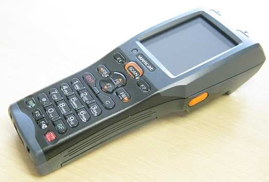
Q98GTX221G
Sep 23, 2012Wireless 2D-code Handy Terminal
Equipment Class
DSS - Part 15 Spread Spectrum Transmitter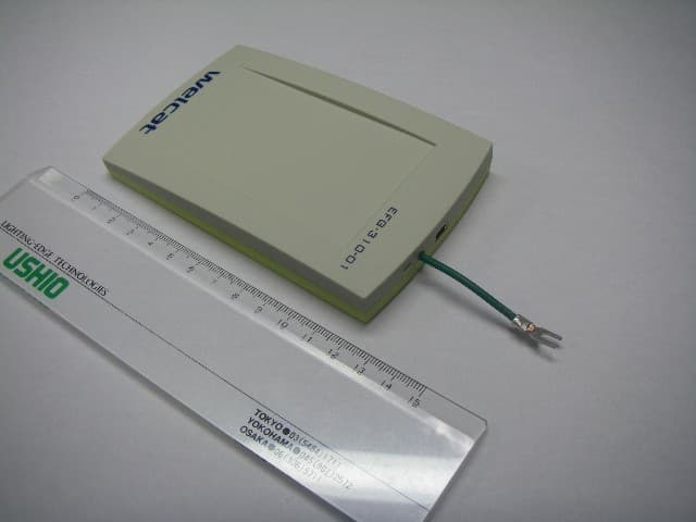
Q98CSH07334
Feb 26, 2008RFID IC Card/IC Tag Reader/Writer
Equipment Class
DXX - Part 15 Low Power Communication Device Transmitter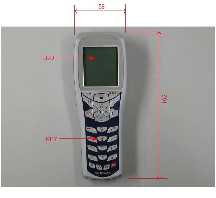
Q98GTX100
Oct 23, 2007Handy Terminal
Equipment Class
DTS - Digital Transmission System