Q98GTX221GWireless 2D-code Handy Terminal
Welcat, Inc.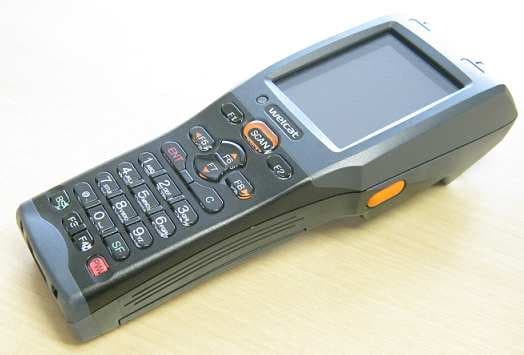
Click to zoom
Application Details
- Equipment Class
- DSS - Part 15 Spread Spectrum Transmitter
- Date of Grant
- Sep 23, 2012
- Application Purpose
- Original Equipment
- Date of Application
- Sep 22, 2012
- Equipment Note
- Wireless 2D-code Handy Terminal
- Frequency Range
- 2402.00000000 - 2480.00000000
- Company
- Welcat, Inc.
- Country
- Japan
Documents & Files
Document Text
Text extracted from the exhibit documents filed with the FCC. Open a document above to read the original.
Users Manual
Wireless Two-dimentional Handy Terminal GTX-221-G User's Manual Trademarks GTX-221-G User’s Manual 1 Trademarks ・ Microsoft and Windows are either registered trademarks or trademarks of Microsoft Corporation in the United States and other countries. ・ Bluetooth is a registered trademark of Bluetooth SIG, Inc. and licensed to and used by Welcat Inc. ・ The bitmap fonts developed by Ricoh Company, Ltd. are installed in the Handy Terminal. ・ The file system "Fugue" developed by Kyoto Software Research, Inc. is installed in the Handy Terminal. Fugue ©1999-2012 Kyoto Software Research, Inc. All rights reserved. ・ Welcat Inc. owns the copyright to this manual. ・ No part of this manual may be used or reproduced without the prior consent of Welcat Inc. ・ Product names and company names indicated in this manual are registered trademarks or trademarks of their respective owners. For Safe and Correct Use GTX-221-G User’s Manual 2 For Safe and Correct Use Thank you for purchasing our product. Before using the Handy Terminal, read this user's manual thoroughly for proper use and maintenance of the product. Check the product's specifications, functions, and details, and when using the product, carefully read instructions marked on the product as well as this manual so that you can properly use the Handy Terminal to avoid any accident. Note that it is also important to perform periodical inspection and maintenance on the product. The following symbols classify and explain the levels of injury and damage that could be caused if using the Handy Terminal improperly by disregarding the safety instructions indicated by the symbols. The symbols are classified by danger level. Danger Indicates an imminently hazardous situation. Improper handling by disregarding this symbol could result in death or serious injury. Warning Indicates a potentially hazardous situation. Improper handling by disregarding this symbol could result in death or serious injury. Caution Indicates a potentially hazardous situation. Improper handling by disregarding this symbol may result in injury or physical damage only. The following symbols classify and explain the safety instructions you must observe: This symbol indicates Prohibited Action. The specific details of prohibited action are indicated in a figure with this symbol. This symbol indicates Mandatory Action. The specific details of mandatory action are indicated in a figure with this symbol. This symbol indicates Alert. The specific details of alert are indicated in a figure with this symbol. To prevent injury to the user and others as well as property damage, observe the precautions described in the subsequent sections. For Safe and Correct Use GTX-221-G User’s Manual 3 Required Precautions To use the Handy Terminal, strictly observe the safety instructions (danger, warning, and alert) recom mended by the manufacturers of the PC and peripherals you are using. Common to GTX-221-G Main Unit and Battery Pack (BP-004) Danger Be sure to use the specified periph erals. ・Battery pack (BP-004) ・Single charger (QC-006) ・Multi charger (QC-007) ・USB communication unit (IU-004) ・USB communication / charging unit (IU-004C) Do not use, leave, or charge the product in a location where the prod uct becomes hot (near fire or a space heater, or under a hot sun) or where a flammable gas may be generated. Otherwise, there is a risk of battery leakage, overheating, explosion, or fire, or the device may become faulty. Do not put the product into a microwave oven or high-pressure container. Otherwise, there is a risk of battery leakage, overheating, explosion, or fire, or the device may become faulty. Do not put the product into fire or heat the product. Otherwise, there is a risk of battery leakage, overheating, explosion, or fire, or the device may become faulty. Do not direct a laser beam toward someone's eyes. If laser light gets in the eyes, there is a risk of damage to eyesight (See "Laser Safety Standard" (P.10)). Do not short-circuit or solder a ter minal such as the battery pack ter minal and the main unit's terminal for battery pack or charging. Otherwise, there is a risk of battery leakage, overheating, explosion, or fire, or the device may become faulty. Do not charge the battery pack with its plus and minus ends reversed. Oth erwise, there is a risk of battery leakage, overheating, explosion, or fire, or the device may become faulty. Do not get the product wet or im merse it in water or sea water. Otherwise, there is a risk of battery leakage, overheating, explosion, or fire, or the device may become faulty. For Safe and Correct Use GTX-221-G User’s Manual 4 Warning While charging the battery pack, if charging does not become complete even after the specified charging time, stop charging. Otherwise, there is a risk of battery leakage, overheating, explosion, or fire, or the de vice may become faulty. Avoid any strong shock or impact by dropping or throwing the product. Otherwise, there is a risk of battery leakage, overheating, explosion, o r fire, or the device may become faulty. When you detect heat, smoke, or abnormal smell, turn the power off and remove the battery pack. If you continue to use the product as- is, there is a risk of overheating or fire. And the battery pack may leak or explode. Do not disassemble or modify the product. Otherwise, there is a risk of such an acci dent as injury, electrical shock, and fire, or the device may become faulty . Ask the retail shop where you purchased the product for inspec- tion and adjustment. Should any problem occur due to modifi cation, we will not take any responsibility. Prevent any part of the body (fingers, hand, etc.) from touching a terminal such as the battery pack terminal and the main unit's terminal for battery pack or charging. Otherwise, there is a risk of elec-trical shock, injury, or the device may become faulty. Keep the product away from any chemicals. Do not use or store the product in a location where chemicals may come…
Text truncated - open the document above for the full version.
Internal Photos
【WLAN Module Appearance】 Top View(Shield is attached)Bo ttom View Top View(Shield is not attached)PCB FrontPCB Back WLAN Antenna WLAN Board Dim ensions:8.2(W)×8.4(D)×1.32(H) [Unit:mm] 【Bl uetooth Module Appearance】 Top ViewBo ttom View PCB FrontPCB Back Bluetooth Ant enna Bluetooth Board Dim ensions:4.9(W)×4.7(D)×1.0(H) [Unit:mm]
Test Report
Test report No. : 32KE0289-SH-01-A Page : 1 of 60 Issued date : September 7, 2012 Revised date : September 20, 2012 FCC ID : Q98GTX221G UL Japan, Inc. Shonan EMC Lab. 1-22-3 Megumigaoka, Hiratsuka-shi, Kanagawa-ken, 259-1220 JAPAN Telephone : +81 463 50 6400 Facsimile : +81 463 50 6401 RADIO TEST REPORT Test Report No.: 32KE0289-SH-01-A Applicant : Welcat Inc. Type of Equipment : Wireless 2D-code Handy Terminal Model No. : GTX-221-G FCC ID : Q98GTX221G Test regulation : FCC Part15 Subpart C: 2012 Test result : Complied 1. This test report shall not be reproduced in full or partial, without the written approval of UL Japan, Inc. 2. The results in this report apply only to the sample tested. 3. This sample tested is in compliance with the limits of the above regulation. 4. The test results in this test report are traceable to the national or international standards. 5. This test report must not be used by the customer to claim product certification, approval, or endorsement by any agency of the Federal Government. 6. The opinions and the interpretations to the result of the description in this report are outside scopes where UL Japan has been accredited. Date of test: August 2 to 22, 2012 Tested by: Shinichi Takano Engineer of WiSE Japan, UL Verification Service Approved by : Toyokazu Imamura Leader of WiSE Japan, UL Verification Service RTL02610 The testing in which "Non-accreditation" is displayed is outside the accreditation scopes in UL Japan. There is no testing item of "Non-accreditation". 13-EM-F0429 Test report No. : 32KE0289-SH-01-A Page : 2 of 60 Issued date : September 7, 2012 Revised date : September 20, 2012 FCC ID : Q98GTX221G UL Japan, Inc. Shonan EMC Lab. 1-22-3 Megumigaoka, Hiratsuka-shi, Kanagawa-ken, 259-1220 JAPAN Telephone : +81 463 50 6400 Facsimile : +81 463 50 6401 REVISION HISTORY Original Test Report No.: 32KE0289-SH-01-A Revision Test report No. Date Page revised Contents - (Original) 32KE0289-SH-01-A September 7, 2012 - - 1 32KE0289-SH-01-A September 20, 2012 P1,2,10 P10 -Addition of comment for test configuration (stand-alone) Test report No. : 32KE0289-SH-01-A Page : 3 of 60 Issued date : September 7, 2012 FCC ID : Q98GTX221G UL Japan, Inc. Shonan EMC Lab. 1-22-3 Megumigaoka, Hiratsuka-shi, Kanagawa-ken, 259-1220 JAPAN Telephone : +81 463 50 6400 Facsimile : +81 463 50 6401 Contents Page SECTION 1: Customer information ........................................................................................ 4 SECTION 2: Equipment under test (E.U.T.) .......................................................................... 4 SECTION 3: Test specification, procedures & results ............................................................ 6 SECTION 4: Operation of E.U.T. during testing .................................................................... 9 SECTION 5: Conducted emission ......................................................................................... 11 SECTION 6: Carrier frequency separation ........................................................................... 12 SECTION 7: 20dB bandwidth & Occupied bandwidth (99%) ............................................ 12 SECTION 8: Number of hopping frequency ......................................................................... 12 SECTION 9: Dwell time ......................................................................................................... 12 SECTION 10: Maximum peak output power........................................................................ 12 SECTION 11: Spurious emissions (Antenna port conducted) .............................................. 13 SECTION 12: Radiated emission........................................................................................... 13 Contents of APPENDIXES ...................................................................................................... 15 APPENDIX 1: Data of radio tests .......................................................................................... 16 APPENDIX 2: Test instruments ............................................................................................ 56 APPENDIX 3: Photographs of test setup .............................................................................. 58 Test report No. : 32KE0289-SH-01-A Page : 4 of 60 Issued date : September 7, 2012 FCC ID : Q98GTX221G UL Japan, Inc. Shonan EMC Lab. 1-22-3 Megumigaoka, Hiratsuka-shi, Kanagawa-ken, 259-1220 JAPAN Telephone : +81 463 50 6400 Facsimile : +81 463 50 6401 SECTION 1: Customer information Company Name : Welcat Inc. Address : 4-12-8 Higashi-Shinagawa, Shinagawa Seaside East Tower 6F, Shinagawa-ku, Tokyo 140-0002 Japan Telephone Number : +81-3-5463-8582 Facsimile Number : +81-3-5463-8587 Contact Person : Masakiyo Yamazaki SECTION 2: Equipment under test (E.U.T.) 2.1 Identification of E.U.T. Type of Equipment : Wireless 2D-code Handy Terminal Model Number : GTX-221-G Serial Number : Refer to clause 4.2. Rating : DC3.8V Country of Mass-production : Japan Condition of EUT : Production prototype (Not for Sale: This sample is equivalent to mass-produced items.) Receipt Date of Sample : August 2, 2012 Modification of EUT : No modification by the test lab. 2.2 Product description Model: GTX-221-G (referred to as the EUT in this report) is a Wireless 2D-code Handy Terminal. Clock frequency(ies) in the system : MAIN CPU:13MHz,32.768MHz Bluetooth Module:16MHz, 26MHz WLAN Module: 38.4MHz Radio specification (WLAN part) Equipment type : Transceiver Frequency of operation : 2412-2462MHz Bandwidth & channel spacing : 20MHz & 5MHz Type of modulation : DSSS: CCK, DQPSK, DBPSK OFDM: 64QAM, 16QAM, QPSK, BPSK ITU code : D1D, G1D Antenna type : PWB Pattern antenna Antenna connector type : None Antenna gain : -0.90 dBi Operation temperature range : -5 to 45 deg.C. * For WLAN part, Refer to the test report: 32KE0289-SH-01-B. Radio specification (Bluetooth part) Equipment type : Transceiver Frequency of operation : 2402-2480MHz Bandwidth…
Text truncated - open the document above for the full version.
Test Report
Test report No. : 32KE0289-SH-02-A Page : 1 of 49 Issued date : September 5, 2012 FCC ID : Q98GTX221G UL Japan, Inc. Shonan EMC Lab. 1-22-3 Megumigaoka, Hiratsuka-shi, Kanagawa-ken, 259-1220 JAPAN Telephone: +81 463 50 6400 / Facsimile: +81 463 50 6401 SAR TEST REPORT Test Report No.: 32KE0289-SH-02-A Applicant : Welcat Inc. Type of Equipment : Wireless 2D-code Handy Terminal Model No. : GTX-221-G FCC ID : Q98GTX221G Test Standard : FCC 47CFR §2.1093, Supplement C (Edition 01-01) to OET Bulletin 65 Test Result : Complied Highest SAR(1g) Value : 0.72 W/kg ((DTS) IEEE 802.11b, 1Mbps(DBPSK/OFDM), 2462MHz) *. Highest SAR(1g) across exposure conditions = 0.72 W/kg = grant listing. 1. This test report shall not be reproduced in full or partial, without the written approval of UL Japan, Inc. 2. The results in this report apply only to the sample tested. 3. This sample tested is in compliance with the limits of the above regulation. 4. The test results in this test report are traceable to the national or international standards. 5. This test report must not be used by the customer to claim product certification, approval, or endorsement by any agency of the Federal Government. 6. The opinions and the interpretations to the result of the description in this report are outside scopes where UL Japan has been accredited. Date of test: August 27, 2012 Test engineer: Hiroshi Naka Engineer of WiSE Japan, UL Verification Service Approved by: Toyokazu Imamura Leader of WiSE Japan, UL Verification Service RTL02610 The testing in which "Non-accreditation" is displayed is outside the accreditation scopes in UL Japan. There is no testing item of "Non-accreditation". 13-EM-F0429 Test report No. : 32KE0289-SH-02-A Page : 2 of 49 Issued date : September 5, 2012 FCC ID : Q98GTX221G UL Japan, Inc. Shonan EMC Lab. 1-22-3 Megumigaoka, Hiratsuka-shi, Kanagawa-ken, 259-1220 JAPAN Telephone: +81 463 50 6400 / Facsimile: +81 463 50 6401 CONTENTS PAGE SECTION 1: Customer information .................................................................................... 3 SECTION 2: Equipment under test (EUT) ......................................................................... 3 SECTION 3: Test specification, procedures and results .................................................... 4 3.1 Test specification ................................................................................................................. 4 3.2 Exposure limit ..................................................................................................................... 4 3.3 Procedure and result ............................................................................................................ 4 3.4 Test location ........................................................................................................................ 5 3.5 Confirmation before SAR testing ......................................................................................... 5 3.6 Confirmation after SAR testing ........................................................................................... 5 3.7 Test setup of EUT and SAR measurement procedure .......................................................... 6 SECTION 4: Operation of EUT during testing .................................................................. 6 SECTION 5: Uncertainty assessment (SAR measurement) ............................................... 7 SECTION 6: Confirmation before testing .......................................................................... 8 SECTION 7: SAR Measurement results ............................................................................. 9 Contents of appendixes APPENDIX 1: Photographs of test setup ............................................................................... 10 Appendix 1-1 Photograph of EUT and antenna position ............................................................................ 10 Appendix 1-2 EUT and support equipment ................................................................................................ 11 Appendix 1-3 Photograph of SAR test setup .............................................................................................. 12 APPENDIX 2: SAR Measurement data ................................................................................. 14 Appendix 2-1 Evaluation procedure ........................................................................................................... 14 Appendix 2-2 Measurement data ................................................................................................................ 15 APPENDIX 3: Test instruments ............................................................................................. 24 Appendix 3-1 Equipment used ................................................................................................................... 24 Appendix 3-2 Dosimetry assessment setup ................................................................................................ 25 Appendix 3-3 Configuration and peripherals .............................................................................................. 25 Appendix 3-4 System components ............................................................................................................. 26 Appendix 3-5 Test system specification ..................................................................................................... 27 Appendix 3-6 Simulated tissues composition ............................................................................................. 27 Appendix 3-7 Simulated tissues parameter confirmation ........................................................................... 28 Appendix 3-8 System check data ............................................................................................................... 28 Appendix 3-9 System check measurement data ...................................................................…
Text truncated - open the document above for the full version.
Test Report
Test report No. : 32KE0289-SH-02-A Page : 14 of 49 Issued date : September 5, 2012 FCC ID : Q98GTX221G UL Japan, Inc. Shonan EMC Lab. 1-22-3 Megumigaoka, Hiratsuka-shi, Kanagawa-ken, 259-1220 JAPAN Telephone: +81 463 50 6400 / Facsimile: +81 463 50 6401 APPENDIX 2: SAR Measurement data Appendix 2-1: Evaluation procedure The SAR evaluation was performed with the following procedure: Step 1: Measurement of the E-field at a fixed location above the central position of flat phantom was used as a reference value for assessing the power drop. Step 2: The SAR distribution at the exposed side of head or body position was measured at a distance of each device from the inner surface of the shell. The area covered the entire dimension of the antenna of EUT and suitable horizontal grid spacing of EUT. Based on these data, the area of the maximum absorption was determined by splines interpolation. Step 3: Around this point found in the Step 2 (area scan), a volume of 30mm(X axis)30mm(Y axis)30mm(Z axis) was assessed by measuring 777 points under 3GHz. And for any secondary peaks found in the Step2 which are within 2dB of maximum peak and not with this Step3 (Zoom scan) is repeated. On the basis of this data set, the spatial peak SAR value was evaluated under the following procedure: (1) The data at the surface were extrapolated, since the center of the dipoles is 1mm away from the tip of the probe and the distance between the surface and the lowest measuring point is 2mm. The extrapolation was based on a least square algorithm [4]. A polynomial of the fourth order was calculated through the points in z-axes. This polynomial was then used to evaluate the points between the surface and the probe tip. (2) The maximum interpolated value was searched with a straightforward algorithm. Around this maximum the SAR values averaged over the spatial volumes (1g or 10g) were computed by the 3D-Spline interpolation algorithm. The 3D-Spline is composed of three one-dimensional splines with the “Not a knot"-condition (in x, y and z-directions) [4], [5]. The volume was integrated with the trapezoidal-algorithm. One thousand points (101010) were interpolated to calculate the average. (3) All neighboring volumes were evaluated until no neighboring volume with a higher average value was found. Step 4: Re-measurement of the E-field at the same location as in Step 1 for the assessment of the power drift. Step 5: Repeat Step 1-Step 4 with other condition or/and setup of EUT. Test report No. : 32KE0289-SH-02-A Page : 15 of 49 Issued date : September 5, 2012 FCC ID : Q98GTX221G UL Japan, Inc. Shonan EMC Lab. 1-22-3 Megumigaoka, Hiratsuka-shi, Kanagawa-ken, 259-1220 JAPAN Telephone: +81 463 50 6400 / Facsimile: +81 463 50 6401 Appendix 2-2: Measurement data Step 1: Worst position search Step 1-1: Front & touch (separation distance=0mm) / 11b(1Mbps), 2462MHz EUT: Wireless 2D-code Handy Terminal ; Type: GTX-221-G; Serial: 21C04 Communication System: IEEE 802.11b(1Mbps, DBPSK/DSSS); Frequency: 2462 MHz; Crest Factor: 1.0 Medium: M2450; Medium parameters used: f = 2462 MHz; σ = 1.99 S/m; ε r = 50.6; ρ = 1000 kg/m 3 DASY4 Configuration: - Probe: EX3DV4 - SN3679; ConvF(6.77, 6.77, 6.77); Calibrated: 2012/06/21 - Sensor-Surface: 2mm (Mechanical Surface Detection) - Electronics: DAE4 Sn626; Calibrated: 2012/02/15 - Phantom: ELI 4.0; Type: QDOVA001BA; Serial: 1059; Phantom section: Flat Section - Measurement SW: DASY4, V4.7 Build 80; Postprocessing SW: SEMCAD, V1.8 Build 184 #1,frt&touch(d0mm),11b(1m,14d),m2462/ Area Scan:210x90,15 (15x7x1): Measurement grid: dx=15mm, dy=15mm; Maximum value of SAR (measured) = 0.485 mW/g Area Scan:210x90,15 (141x61x1): Measurement grid: dx=15mm, dy=15mm; Maximum value of SAR (interpolated) = 0.633 mW/g Z Scan:160,5 (1x1x33): Measurement grid: dx=20mm, dy=20mm, dz=5mm; Maximum value of SAR (measured) = 0.593 mW/g Zoom Scan:30x30x30,5 (7x7x7)/Cube 0: Measurement grid: dx=5mm, dy=5mm, dz=5mm; Reference Value = 15.9 V/m; Power Drift = -0.136 dB, Maximum value of SAR (measured) = 0.598 mW/g Peak SAR (extrapolated) = 0.809 W/kg SAR(1 g) = 0.402 mW/g; SAR(10 g) = 0.196 mW/g Remarks: *. Date tested: 2012/08/27; Tested by: Hiroshi Naka; Tested place:No.7 shielded room, *.liquid depth: 154mm; Position: distance of EUT to phantom: 0mm (2mm to liquid); ambient: 24.6deg.C. / 44 %RH, *.liquid temperature: 22.9(start)/22.9(end)/23.0(in check) deg.C.; *.White cubic: zoom scan area, Red cubic: big=SAR(10g )/small=SAR(1g) Test report No. : 32KE0289-SH-02-A Page : 16 of 49 Issued date : September 5, 2012 FCC ID : Q98GTX221G UL Japan, Inc. Shonan EMC Lab. 1-22-3 Megumigaoka, Hiratsuka-shi, Kanagawa-ken, 259-1220 JAPAN Telephone: +81 463 50 6400 / Facsimile: +81 463 50 6401 Appendix 2-2: Measurement data (cont’d) Step 1: Worst position search (cont’d) Step 1-2: Top-front & touch (separation distance=0mm) / 11b(1Mbps), 2462MHz ->Worst SAR(1g) of Wi-Fi mode EUT: Wireless 2D-code Handy Terminal ; Type: GTX-221-G; Serial: 21C04 Communication System: IEEE 802.11b(1Mbps, DBPSK/DSSS); Frequency: 2462 MHz; Crest Factor: 1.0 Medium: M2450; Medium parameters used: f = 2462 MHz; σ = 1.99 S/m; ε r = 50.6; ρ = 1000 kg/m 3 DASY4 Configuration: - Probe: EX3DV4 - SN3679; ConvF(6.77, 6.77, 6.77); Calibrated: 2012/06/21 - Sensor-Surface: 2mm (Mechanical Surface Detection) - Electronics: DAE4 Sn626; Calibrated: 2012/02/15 - Phantom: ELI 4.0; Type: QDOVA001BA; Serial: 1059; Phantom section: Flat Section - Measurement SW: DASY4, V4.7 Build 80; Postprocessing SW: SEMCAD, V1.8 Build 184 #2a,top&touch(d0mm),11b(1m,14d),m2462/ Area Scan:90x90,15 (7x7x1): Measurement grid: dx=15mm, dy=15mm; Maximum value of SAR (measured) = 1.07 mW/g Area Scan:90x90,15 (61x61x1): Measurement grid: dx=15mm, dy=15mm; Maximum value of SAR (interpolated) = 1.16 mW/g Z Scan:160,5 (1x1x33): Measurement grid: dx=20mm, dy=20mm, dz=5mm; Maximum value of SAR (measured) = 1.15 mW/g Zoom Scan:30x30x30,5 (7x7x7)/Cube 0: Measurement grid: dx=5mm, dy=5mm, dz=5mm; Referenc…
Text truncated - open the document above for the full version.
Test Report
Test report No. : 32KE0289-SH-02-A Page : 30 of 49 Issued date : September 5, 2012 FCC ID : Q98GTX221G UL Japan, Inc. Shonan EMC Lab. 1-22-3 Megumigaoka, Hiratsuka-shi, Kanagawa-ken, 259-1220 JAPAN Telephone: +81 463 50 6400 / Facsimile: +81 463 50 6401 Appendix 3-11: Calibration certificate: Dipole (D2450V2) (sn:822) Test report No. : 32KE0289-SH-02-A Page : 31 of 49 Issued date : September 5, 2012 FCC ID : Q98GTX221G UL Japan, Inc. Shonan EMC Lab. 1-22-3 Megumigaoka, Hiratsuka-shi, Kanagawa-ken, 259-1220 JAPAN Telephone: +81 463 50 6400 / Facsimile: +81 463 50 6401 Appendix 3-11: Calibration certificate: Dipole (D2450V2) (sn:822) (cont’d) Test report No. : 32KE0289-SH-02-A Page : 32 of 49 Issued date : September 5, 2012 FCC ID : Q98GTX221G UL Japan, Inc. Shonan EMC Lab. 1-22-3 Megumigaoka, Hiratsuka-shi, Kanagawa-ken, 259-1220 JAPAN Telephone: +81 463 50 6400 / Facsimile: +81 463 50 6401 Appendix 3-11: Calibration certificate: Dipole (D2450V2) (sn:822) (cont’d) Test report No. : 32KE0289-SH-02-A Page : 33 of 49 Issued date : September 5, 2012 FCC ID : Q98GTX221G UL Japan, Inc. Shonan EMC Lab. 1-22-3 Megumigaoka, Hiratsuka-shi, Kanagawa-ken, 259-1220 JAPAN Telephone: +81 463 50 6400 / Facsimile: +81 463 50 6401 Appendix 3-11: Calibration certificate: Dipole (D2450V2) (sn:822) (cont’d) Test report No. : 32KE0289-SH-02-A Page : 34 of 49 Issued date : September 5, 2012 FCC ID : Q98GTX221G UL Japan, Inc. Shonan EMC Lab. 1-22-3 Megumigaoka, Hiratsuka-shi, Kanagawa-ken, 259-1220 JAPAN Telephone: +81 463 50 6400 / Facsimile: +81 463 50 6401 Appendix 3-11: Calibration certificate: Dipole (D2450V2) (sn:822) (cont’d) Test report No. : 32KE0289-SH-02-A Page : 35 of 49 Issued date : September 5, 2012 FCC ID : Q98GTX221G UL Japan, Inc. Shonan EMC Lab. 1-22-3 Megumigaoka, Hiratsuka-shi, Kanagawa-ken, 259-1220 JAPAN Telephone: +81 463 50 6400 / Facsimile: +81 463 50 6401 Appendix 3-11: Calibration certificate: Dipole (D2450V2) (sn:822) (cont’d) Test report No. : 32KE0289-SH-02-A Page : 36 of 49 Issued date : September 5, 2012 FCC ID : Q98GTX221G UL Japan, Inc. Shonan EMC Lab. 1-22-3 Megumigaoka, Hiratsuka-shi, Kanagawa-ken, 259-1220 JAPAN Telephone: +81 463 50 6400 / Facsimile: +81 463 50 6401 Appendix 3-11: Calibration certificate: Dipole (D2450V2) (sn:822) (cont’d) Test report No. : 32KE0289-SH-02-A Page : 37 of 49 Issued date : September 5, 2012 FCC ID : Q98GTX221G UL Japan, Inc. Shonan EMC Lab. 1-22-3 Megumigaoka, Hiratsuka-shi, Kanagawa-ken, 259-1220 JAPAN Telephone: +81 463 50 6400 / Facsimile: +81 463 50 6401 Appendix 3-11: Calibration certificate: Dipole (D2450V2) (sn:822) (cont’d) Test report No. : 32KE0289-SH-02-A Page : 38 of 49 Issued date : September 5, 2012 FCC ID : Q98GTX221G UL Japan, Inc. Shonan EMC Lab. 1-22-3 Megumigaoka, Hiratsuka-shi, Kanagawa-ken, 259-1220 JAPAN Telephone: +81 463 50 6400 / Facsimile: +81 463 50 6401 Appendix 3-12: Calibration certificate: E-Field Probe (EX3DV4) (sn:3679) Test report No. : 32KE0289-SH-02-A Page : 39 of 49 Issued date : September 5, 2012 FCC ID : Q98GTX221G UL Japan, Inc. Shonan EMC Lab. 1-22-3 Megumigaoka, Hiratsuka-shi, Kanagawa-ken, 259-1220 JAPAN Telephone: +81 463 50 6400 / Facsimile: +81 463 50 6401 Appendix 3-12: Calibration certificate: E-Field Probe (EX3DV4) (sn:3679) (cont’d) Test report No. : 32KE0289-SH-02-A Page : 40 of 49 Issued date : September 5, 2012 FCC ID : Q98GTX221G UL Japan, Inc. Shonan EMC Lab. 1-22-3 Megumigaoka, Hiratsuka-shi, Kanagawa-ken, 259-1220 JAPAN Telephone: +81 463 50 6400 / Facsimile: +81 463 50 6401 Appendix 3-12: Calibration certificate: E-Field Probe (EX3DV4) (sn:3679) (cont’d) Test report No. : 32KE0289-SH-02-A Page : 41 of 49 Issued date : September 5, 2012 FCC ID : Q98GTX221G UL Japan, Inc. Shonan EMC Lab. 1-22-3 Megumigaoka, Hiratsuka-shi, Kanagawa-ken, 259-1220 JAPAN Telephone: +81 463 50 6400 / Facsimile: +81 463 50 6401 Appendix 3-12: Calibration certificate: E-Field Probe (EX3DV4) (sn:3679) (cont’d) Test report No. : 32KE0289-SH-02-A Page : 42 of 49 Issued date : September 5, 2012 FCC ID : Q98GTX221G UL Japan, Inc. Shonan EMC Lab. 1-22-3 Megumigaoka, Hiratsuka-shi, Kanagawa-ken, 259-1220 JAPAN Telephone: +81 463 50 6400 / Facsimile: +81 463 50 6401 Appendix 3-12: Calibration certificate: E-Field Probe (EX3DV4) (sn:3679) (cont’d) Test report No. : 32KE0289-SH-02-A Page : 43 of 49 Issued date : September 5, 2012 FCC ID : Q98GTX221G UL Japan, Inc. Shonan EMC Lab. 1-22-3 Megumigaoka, Hiratsuka-shi, Kanagawa-ken, 259-1220 JAPAN Telephone: +81 463 50 6400 / Facsimile: +81 463 50 6401 Appendix 3-12: Calibration certificate: E-Field Probe (EX3DV4) (sn:3679) (cont’d) Test report No. : 32KE0289-SH-02-A Page : 44 of 49 Issued date : September 5, 2012 FCC ID : Q98GTX221G UL Japan, Inc. Shonan EMC Lab. 1-22-3 Megumigaoka, Hiratsuka-shi, Kanagawa-ken, 259-1220 JAPAN Telephone: +81 463 50 6400 / Facsimile: +81 463 50 6401 Appendix 3-12: Calibration certificate: E-Field Probe (EX3DV4) (sn:3679) (cont’d) Test report No. : 32KE0289-SH-02-A Page : 45 of 49 Issued date : September 5, 2012 FCC ID : Q98GTX221G UL Japan, Inc. Shonan EMC Lab. 1-22-3 Megumigaoka, Hiratsuka-shi, Kanagawa-ken, 259-1220 JAPAN Telephone: +81 463 50 6400 / Facsimile: +81 463 50 6401 Appendix 3-12: Calibration certificate: E-Field Probe (EX3DV4) (sn:3679) (cont’d) Test report No. : 32KE0289-SH-02-A Page : 46 of 49 Issued date : September 5, 2012 FCC ID : Q98GTX221G UL Japan, Inc. Shonan EMC Lab. 1-22-3 Megumigaoka, Hiratsuka-shi, Kanagawa-ken, 259-1220 JAPAN Telephone: +81 463 50 6400 / Facsimile: +81 463 50 6401 Appendix 3-12: Calibration certificate: E-Field Probe (EX3DV4) (sn:3679) (cont’d) Test report No. : 32KE0289-SH-0…
Text truncated - open the document above for the full version.
Contact Information
Applicant
Masakiyo Yamazaki(R&D Dept. Chief Clerk)
Technical Contact
[email protected]Toyokazu Imamura
[email protected]81-463-50-6400
1-22-3 Megumigaoka, Hiratsuka-shi, · Kanagawa-ken, · Japan
Test Firm
UL Japan, Inc. Shonan EMC EMC Lab.Tetsuya Hashimoto
Technical Specifications
| # | Rule Parts | Frequency Range | Power Output |
|---|---|---|---|
| 1 | 15C | 2.40 GHz - 2.48 GHz | 1.90 mW |
Other Applications from Welcat, Inc.
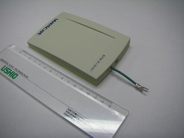
Q98CSH07334
Feb 26, 2008RFID IC Card/IC Tag Reader/Writer
Equipment Class
DXX - Part 15 Low Power Communication Device Transmitter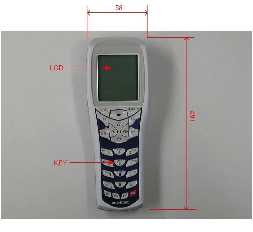
Q98GTX100
Oct 23, 2007Handy Terminal
Equipment Class
DTS - Digital Transmission System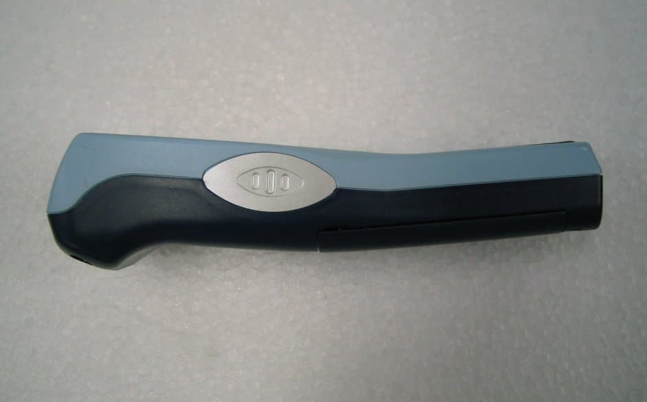
Q98XIT100BW
Dec 19, 2005Barcode Reader with 802.11b&Bluetooth Transmitters
Equipment Class
DTS - Digital Transmission System