Q9LGG03Bluetooth Headset
G.G. Telecom (2002) Incorporated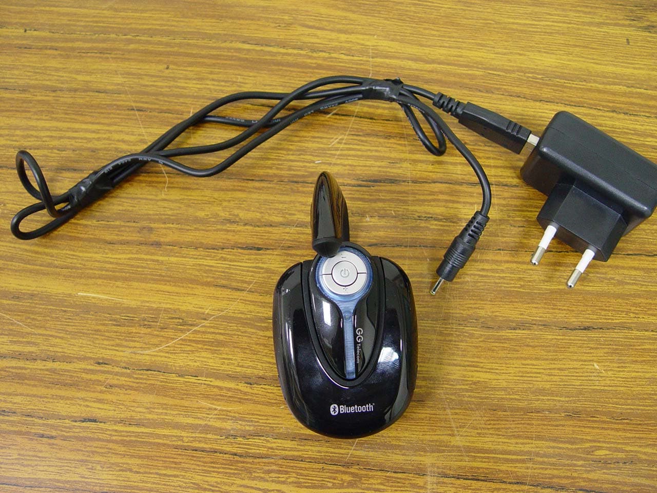
Click to zoom
Application Details
- Equipment Class
- DSS - Part 15 Spread Spectrum Transmitter
- Date of Grant
- Oct 26, 2004
- Application Purpose
- Original Equipment
- Date of Application
- Oct 26, 2004
- Equipment Note
- Bluetooth Headset
- Frequency Range
- 2402.00000000 - 2480.00000000
- Country
- Taiwan
Documents & Files
Document Text
Text extracted from the exhibit documents filed with the FCC. Open a document above to read the original.
Users Manual
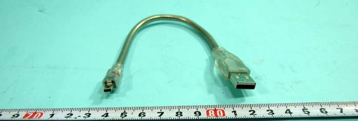
Introduction 1-2 Gg03 overview 3 -5 Getting started 6-11 Wearing the Gg03 11-12 Using the Gg03 13-18 Using the Gg03 with multiple Bluetooth devices 19-23 Function / Button matrix 24-25 LED indicator chart 26-27 Audio indicator chart 28 Additional i nformation 29-34 Declaration of c onformity 35-36 Regulatory information 37 4F,#9,All y 2,Lane 35.Ji-Hu Rd., NeiHu, Taipei Cit y 114,Taiwan, R.O.C. http:/www.gg2002.com 0102 Handle incoming and outgoing calls.Adjust the volume.Mute the microphone.Voice dialing (if your phone supports this function).Last call redial (if your phone supports Handsfree profile).Reject the incoming call (if your phone supports Handsfree profile). What's in the package?The Gg03 Bluetooth headset package comes equipped with a headset and a charging solution. In this package you will find: One Gg03 Bluetooth headset.One portable charging cradle.One 100-240V power adapter.One USB charging cable.One user guide. Introduction lntroduction Your Bluetooth headset Gg03 is a portable headset solution based on Bluetooth wireless technology.Please read the "Additional Information ” before using your headset. What is Bluetooth w ireless t echnology? Bluetooth is the most advanced cable-replacement technology available today. It enables effortless,cable-free connections between your Bluetooth devices. The Gg03 and the Bluetooth enabled phonecan communicate within the range up to 10m (30 ft) outdoors or up to 5m (15 ft) indoors with no solidobjects in between. How to u se t he Gg03? The Gg03 is a Bluetooth V1.2 qualified product and supports both Headset profile and Handsfreeprofile. The Gg03 can store information and wirelessly interacts with up to three different BluetoothV1.1/V1.2 compliant devices, including mobile phones, PDAs and PCs or any Bluetooth enableddevice that supports Headset profile or Handsfree profile. This manual focuses on how to use theGg03 with your Bluetooth enabled phone. When the Gg03 is connected to your phone, you can do: Gg03 Overview 0304 1.Indicator LED There are 3 colors(blue/red/purple) to show the status of the Gg03.2.Multifunction buttonTo answer, end, reject a call and control advance functions by constituting withvolume control button (please refer to the Function/Button matrix).3.Volume control buttonTo increase or decrease the volume of speaker and control advance functionsby constituting with MFB (please refer to the Function/Button matrix).4.Ear-hookTo wear the headset on your ear, you can switch the direction as your habit. Gg03 Overview Getting started 0506 Getting started Before you can use the Gg03, you must do following two things:1. Charge the Gg03 battery, using an appropriate G.G. Telecom charger.2. Pair the Gg03 with a Bluetooth enabled device, for example, a mobile phone.ChargingThe Gg03 comes with a built-in rechargeable battery. For the first time use, you need to charge for4 hours. During charging, the indicator shows a steady red light. When the battery is fully charged,the red light is off. It takes 90-120 minutes to fully charge the battery. Do not charge the Gg03 formore than 1 day. The talk time of Gg03 is about 8 hours, and the standby time is about 220 hours.The more you talk using the Gg03, the less standby time your battery has. The Gg03 requirelonger charging times when not used over extended periods of time. 5. Speaker:Plays the sound you receive on the call or the audio indicators (please referto the audio indicator chart).6. Microphone:Voice input for outgoing voice.7. Charging port:Approaching with the cradle to charging the battery of your headset.8. Charging Cradle:Design for charging the headset by multiple power supplier such as switchingadaptor, USB cable or car charger. Getting started 0708 To charge the Gg03 1. Make sure the earhook forms an angle of 90 ̊ . 2. Put the Gg03 on to the cradle. 3. It takes 90-120 minutes to fully recharge the battery.4. Press the buttons on the both side of your cradle to remove the Gg03 from your cradle. 1 2 3 4 Getting started 0910 PairingPower on the Gg03Long press the MFB , then you will hear a power on melody and the blue indicator will quickly flash twice. You could start the operation now.Note 1:The first time the Gg03 is turned on, it might automatically be ready for pairing. Note 2:Long press: It refers to press and release and the duration is more than 3 seconds. After long press,you should hear 1 long beep.Short press: It refers to press and release and the duration is less than 1 second. After short press,you should hear 1 short beep.Power off the Gg03 Long press the MFB , then you will hear a power off melody and the red indicator will quickly flash twice. Pairing the Gg03 with your phonePair the Gg03 with your phone by adding it to the list of paired devices in your phone. The Gg03should be paired once with your phone before use. The two devices then recognize each otherwhen they connect. You do not need to pair it again until you want to use the Gg03 with anotherdevice or the pairing information is deleted from your phone. It is recommended that the distancebetween the Gg03 and your phone is as close as possible with no solid objects in between.1. Put the Gg03 enter pairing mode by long pressing the Volume up button . You can see the blue indicator and the red indicator cross blink per second, now the Gg03 is waiting for pairingnow. You can only put the Gg03 into pairing mode when it is in standby mode (please refer tothe LED indicator chart). 2. Perform a "Bluetooth device discovery" from the mobile phone. Wearing the Gg03 1112 3. Select the Gg03 from the discovered devices list and confirm the following on screen prompts.4. When prompted by your phone, enter the passkey “ 1234 ” and the Gg03 will confirm to pair successfully with a pairing success melody. Note:If the Gg03 is not successfully paired within 2 minutes, it will automatically leave pairing mode. Ifthere is no paired data in the paired devices list of the Gg03, it will power off otherwise get intosta…
Text truncated - open the document above for the full version.
Cover Letter(s)
1 Helen Zhao Subject:FW: ??: RE: ??: RE: ??: RE: ??: FW: G.G.TELECOM(2002)INCORPORATED, FCC ID: Q9LGG03, Assessment NO.: AN04T4246, Notice#1 -----Original Message----- From: [email protected] [mailto:[email protected] <mailto:[email protected]> ]On Behalf Of [email protected] Sent: Tuesday, October 26, 2004 1:41 AM To: Helen Zhao Cc: '[email protected]'; Mike Kuo Subject: ??: RE: ??: FW: G.G.TELECOM(2002)INCORPORATED, FCC ID: Q9LGG03, Asse ssment N O.: AN04T4246, Notice#1 Hi Helen, Please refer to the attached for revised test report. (See attached file: Gg03 Test Rpt revised 1026.pdf) Thank you in advance for your assistance. BR, Ting -----Original Message----- From: Compliance Certification Services [mailto:[email protected] <mailto:[email protected]> ] Sent: Friday, October 22, 2004 5:30 PM To: Helen Zhao Subject: G.G.TELECOM(2002)INCORPORATED, FCC ID: Q9LGG03, Assessment NO.: AN04T4246, Notice#1 Question #1: The user manual indicates that the charging cradle is designed to charge the headset either by AC/DC adaptor or USB cable (through PC). But the test report shows the powerline conducted emission test was done with USB cable (through PC) only. Please provide additional test data with AC/DC adapter. Best regards, Helen Zhao The items indicated above must be submitted before processing can continue on the above referenced application. Failure to provide the requested information within 30 days of the original e-mail date may result in 2 application dismissal and forfeiture of the filing fee. Also, please note that partial responses increase processing time and should not be submitted. Any questions about the content of this correspondence should be directed to the e-mail address listed below the name of the sender.
External Photos
Compliance Certification Services Inc. Report No: 40913007 Date of Issue: September 16, 2004 Page 1 of 6 EXTERNAL PHOTOGRPHS OF EUT Compliance Certification Services Inc. Report No: 40913007 Date of Issue: September 16, 2004 Page 2 Compliance Certification Services Inc. Report No: 40913007 Date of Issue: September 16, 2004 Page 3 Compliance Certification Services Inc. Report No: 40913007 Date of Issue: September 16, 2004 Page 4
ID Label/Location Info
G.G. Telecom (2002) Inc. Model: Gg03 FCC ID: Q9LGG03 33mm 10mm
Internal Photos
Compliance Certification Services Inc. Report No: 40913007 Date of Issue: September 16, 2004 Page 5 INTERNAL PHOTOGRPHS OF EUT Compliance Certification Services Inc. Report No: 40913007 Date of Issue: September 16, 2004 Page 6
Parts List/Tune Up Info
HIGH FREQUENCY SMD type antennas for BT/802.11b/g application 2.45 GHz size 5.2 × 3.0 DATA SHEET Product specification – Jul 15, 2004 V.3 Phycomp Product specification High Frequency SMD type antennas for BT/802.11b/g application 2.45 GHz size 5.3 × 2.0 2004 Jul 15 Rev.3 2 www.yageo.com QUICK REFERENCE DATA DESCRIPTION VALUE Centre frequency 2.45 GHz 0 type/01type/02 type/03 type/Default/04 type/05 type Bandwidth >100 MHz Gain 4 dBi max. (depends on the special environment) VSWR 2.5 max. (depends on the special environment) Polarization Linear Azimuth beam width Omni-directional Impedance 50 Ω Power dissipation 1 W Operating temperature −55 to +85 °C Terminations NiSn Resistance to soldering heat 260 °C for 10 seconds DESCRIPTION This 2.45 GHz ceramic multilayer antenna has been designed to meet the requirements of the Bluetooth TM(1) and IEEE 802.11b/g wireless communications protocol. It consists of a rectangular block of low-dielectric ceramic material and is fabricated in a water-based non-toxic process. The antenna is capable of providing good connectivity using near 50 Ω microstrip directly onto the PC board. Notes 1. Bluetooth is a trademark owned by Telefonieaktiebolaget L M Ericsson, Sweden. FEATURES • Designed for 2.45 GHz ISM-band • Simplifies antenna circuitry • NiSn lead-free terminations • Suitable for wave and reflow soldering • Supplied in tape on reel. APPLICATIONS • Telecommunications • Computing (PCs, printers, PDAs) • Wireless office data communications including WLAN • Consumer electronics (wireless headphones). Phycomp Product specification High Frequency SMD type antennas for BT/802.11b/g application 2.45 GHz size 5.3 × 2.0 MECHANICAL DATA For dimensions see Table 1. Fig.1. Component outline. L W F W F IWA0001 T C C Physical dimensions Table 1 Antenna dimensions SYMBOL DETAILS DIMENSIONS (mm) L − 5.3 ±0.20 W − 2.0 ±0.20 T − 1.3 ±0.20 F feed termination 2.0 ±0.20 C − 0.4 ±0.25 2004 Jul 15 Rev.3 3 www.yageo.com Phycomp Product specification High Frequency SMD type antennas for BT/802.11b/g application 2.45 GHz size 5.3 × 2.0 2004 Jul 15 Rev.3 4 www.yageo.com For dimensions see Table 2. Fi g.2. Recommend dimensions of solder W L C C Antenna F L 1 IWA0002 FOOTPRINT DIMENSIONS Physical dimensions Table 2 The dimensions of antenna appearance SYMBOL DETAILS DIMENSIONS (mm) L − 5.5 ±0.2 W − 2.2 ±0.2 F feed pad 2.2 ±0.2 C − 0.5 ±0.25 L1 − 4.3 ±0.5 ELECTRICAL CHARACTERISTICS DESCRIPTION VALUE Centre frequency 2.45 GHz 0 type/01type/02 type/03 type/Default/04 type/05 type Bandwidth >100 MHz Gain 4 dBi max. (depends on the special environment) VSWR 2.5 max. (depends on the special environment) Polarization Linear Azimuth beam width Omni-directional Impedance 50 Ω Power dissipation 1 W Operating temperature −55 to +85 °C Terminations NiSn Resistance to soldering heat 260 °C for 10 s Weight 0.05 g/piece Phycomp Product specification High Frequency SMD type antennas for BT/802.11b/g application 2.45 GHz size 5.3 × 2.0 2004 Jul 15 Rev.3 5 www.yageo.com Physical dimensions Table 3 The dimensions of test board SYMBOL DETAILS DIMENSIONS (mm) L1 − 30 L2 − 10.5 W − 18 T − 0.8 T1 − 4.0 T2 − 1.0 T3 − 1.5 T4 − 4.8 T5 − 1.5 T6 − 1.5 50 Ω transmisson line SMA connector Antenna chip Ground areaClear area IWA0003 T 3 T 1 T 2 L 1 L 2 W T 4 T T 6 Magnification of clear area T 5 For dimensions see Table 3. Fig.3. Typical FR4 test board. ANTENNA CHARACTERISTICS IN STANDRD TEST BOARD Phycomp Product specification High Frequency SMD type antennas for BT/802.11b/g application 2.45 GHz size 5.3 × 2.0 2004 Jul 15 Rev.3 6 www.yageo.com Pre-tuning reference only,after-tuning performance is depending on customer installation. Fig.4 The measurements of typical SWR and return loss on standard test board . Marker data: 1: Γ= −10 dB; f= 2.33 GHz 2: Γ= −10 dB; f= 2.60 GHz Marker data: 1: SWR= 2.5; f= 2.30 GHz 2: SWR= 2.5; f= 2.70 GHz 2.02.13.0 f (GHz) SWR 1.0 2.0 3.0 5.0 7.0 6.0 8.0 9.0 10.0 4.0 2.22.32.42.52.62.72.82.9 IWA0004 1 2 2.02.13.0 f (GHz) Γ (dB) 45 40 35 25 15 20 10 5 0 30 2.22.32.42.52.62.72.82.9 IWA0005 1 2 Phycomp Product specification High Frequency SMD type antennas for BT/802.11b/g application 2.45 GHz size 5.3 × 2.0 XY plane YZ plane XZ plane − 270° −180° − 90° 0° 0° 0° −180° − 270° − 90° − 270° − 90° −180° 0° IWA0007 Fig.5 The definitions of X-Y-Z plane and angle for radiation pattern 10 −20 −3040 dBi 1020−3040 1020−3040 XYXZYZ Vertical Horizontal 0° −90°−270° −180° IWA0006 0° −90°−270° −180° −180° 0° −90°−270° 0 − − dBi 0−−− dBi 0−−− Table 4 Max. and avg. antenna gain value of radiation pattern Plane XY (dBi) XZ(dBi) YZ (dBi) Vertical Pol. (max.) −3.8 2.6 −1.8 Vertical Pol. (avg.) −8.4 −1.6 −9.7 Horizontal Pol. (max.) 4.0 −1.9 2.7 Horizontal Pol. (avg.) −2.2 −8.4 −2.1 Total gain (max.) 4.0 2.7 2.7 Total gain (avg.) −1.9 −1.3 −1.9 For antenna gain value see Table 4. Fig.6 Radiation pattern measurements 2004 Jul 15 Rev.3 7 www.yageo.com Phycomp Product specification High Frequency SMD type antennas for BT/802.11b/g application 2.45 GHz size 5.3 × 2.0 ORDERING INFORMATION Components may be ordered by using either a Phycomp’s unique 12NC or the simple 17-digit clear text code (Yageo part number) 12NC ORDERING CODE E XAMPLE: 4311 153 00245 4 3 X X 1 5 3 0 0 2 X X Centre frequency Tolerance Size 5.3 x 2.0 x 1.3 mm 53 Packing 11 13 reel: ∅180 mm; 7", blister, 1000 pcs bulk, 1000 pcs Material 1high-frequency material Family 43antenna IWA0008 2452.45 GHz Default 00 at 100 MHz Impedance Bandwidth 2002.00 GHz 00type 2102.10 GHz 01type 2302.30 GHz 03type 2402.40 GHz 04type 2202.20 GHz 02type 2502.50 GHz 05type Yageo part number E XAMPLE: CAN4311153002451K DESCRIPTION CODE Family CAN43 = antenna products Packing 11 = 180 mm/7” blister Materials 1 = high frequency materials Size 53 = 5.3 × 2.0 × 1.3 mm Tolerance 00 = large than 100 MHz Working Frequency (1) 245 = 2.45 GHz (Default) 200 = 2.0 GHz (00 type) 210 = 2.1 GHz (01 type) 220 = 2.2 GHz (02 type) 230 = 2.3 GHz (03 type) 240 = 2.4 GHz (04 type) 250…
Text truncated - open the document above for the full version.
Test Report
Compliance Certification Services Inc. Report No: 40913007-RP1 FCC ID: Q9LGG03 Date of Issue: October 06, 2004 Note: This report shall not be reproduced except in full, without the written approval of Compliance Certification Services Inc. This document may be altered or revised by Compliance Certification Services Inc. personnel only, and shall be noted in the revision section of the document. Page 1 of 49 FCC 47 CFR PART 15 SUBPART C TEST REPORT For G. G. Te l e c o m ( 2 0 0 2 ) I n c . Bluetooth Headset Model: Gg03 Trade Name: GGTelecom Prepared for G. G. Te l e c o m ( 2 0 0 2 ) I n c . 4F, #9, Alley2, Lane 35. Ji-Hu Rd., NeiHu, Taipei City 114, Taiwan, R.O.C. Prepared by Compliance Certification Services Inc. No. 81-1, Lane 210, Bade Rd. 2, Luchu Hsiang, Taoyuan Hsien, (338) Taiwan, R.O.C. TEL: 886-3-324-0332 FAX: 886-3-324-5235 Compliance Certification Services Inc. Report No: 40913007-RP1 FCC ID: Q9LGG03 Date of Issue: October 06, 2004 Page 2 TABLE OF CONTENTS 1. TEST RESULT CERTIFICATION....................................................................................................3 2. EUT DESCRIPTION ...........................................................................................................................4 3. TEST METHODOLOGY ....................................................................................................................5 3.1 EUT CONFIGURATION........................................................................................................................5 3.2 EUT EXERCISE....................................................................................................................................5 3.3 GENERAL TEST PROCEDURES.............................................................................................................5 3.4 FCC PART 15.205 RESTRICTED BANDS OF OPERATIONS........................................................6 3.5 DESCRIPTION OF TEST MODES...........................................................................................................6 4. INSTRUMENT CALIBRATION........................................................................................................7 5. FACILITIES AND ACCREDITATIONS ..........................................................................................8 5.1 FACILITIES ........ ...............................................................................................................................8 5.2 EQUIPMENT........................................................................................................................................8 5.3 LABORATORY ACCREDITATIONS AND LISTING..................................................................................8 5.4 TABLE OF ACCREDITATIONS AND LISTINGS.......................................................................................9 6. SETUP OF EQUIPMENT UNDER TEST .......................................................................................10 6.1 SETUP CONFIGURATION OF EUT.......................................................................................................10 6.2 SUPPORT EQUIPMENT ...............................................................................................................10 7. FCC PART 15.247 REQUIREMENTS.............................................................................................11 7.1 PEAK POWER....................................................................................................................................11 7.2 BAND EDGES MEASUREMENT ................................................................................................12 7.3 PEAK POWER SPECTRAL DENSITY....................................................................................................17 7.4 FREQUENCY SEPARATION.......................................................................................................20 7.5 NUMBER OF HOPPING FREQUENCY ......................................................................................22 7.6 TIME OF OCCUPANCY (DWELL TIME)...................................................................................24 7.7 RADIO FREQUENCY EXPOSURE........................................................................................................31 7.8 SPURIOUS EMISSIONS ................................................................................................................32 7.9 POWERLINE CONDUCTED EMISSIONS...............................................................................................45 APPENDIX 1 PHOTOGRPHS OF TEST SETUP .................................................................................48 Compliance Certification Services Inc. Report No: 40913007-RP1 FCC ID: Q9LGG03 Date of Issue: October 06, 2004 Page 4 2. EUT DESCRIPTION Product Bluetooth Headset Trade Name GGTelecom Model Number Gg03 Model Discrepancy N/A Power Supply Model Number:17M108005 I/P: 100-240VAC, 50-60Hz, 0.2A O/P: 5.0VDC, 250mA Frequency Range 2402 ~ 2480 MHz Transmit Power 4.37 dBm Modulation Technique FHSS Transmit Data Rate 1MHz Number of Channels 79 Channels Antenna Specification SMD Type Antenna / Gain: 4.0 dBi Note: This submittal(s) (test report) is intended for FCC ID: Q9LGG03 filing to comply with Section 15.207, 15.209 and 15.247 of the FCC Part 15, Subpart C Rules. Compliance Certification Services Inc. Report No: 40913007-RP1 FCC ID: Q9LGG03 Date of Issue: October 06, 2004 Page 5 3. TEST METHODOLOGY The tests documented in this report were performed in accordance with ANSI C63.4 and FCC CFR 47 2.1046, 2.1047, 2.1049, 2.1051, 2.1053, 2.1055, 2.1057, 15.207, 15.209 and 15.247. 3.1 EUT CONFIGURATION The EUT configuration for testing is installed on RF field strength measurement to meet the Commissions requirement and operating in a manner that intends to maximize its emission characteristics in a continuous normal application. 3.2 EUT EXERCISE The EUT was operated in the enginee…
Text truncated - open the document above for the full version.
Test Setup Photos
Compliance Certification Services Inc. Report No: 40913007-RP1 FCC ID: Q9LGG03 Date of Issue: October 06, 2004 Page 48 APPENDIX 1 PHOTOGRPHS OF TEST SETUP Radiated Emission Set up Photos Compliance Certification Services Inc. Report No: 40913007-RP1 FCC ID: Q9LGG03 Date of Issue: October 06, 2004 Page 49 Conducted Emission Set Up Photos
Contact Information
Applicant
Allan Wu(CTO)
Test Firm
Compliance Certification Services Inc.Tony Houng
Technical Specifications
| # | Rule Parts | Frequency Range | Power Output |
|---|---|---|---|
| 1 | 15C | 2.40 GHz - 2.48 GHz | 2.74 mW |
Other Applications from G.G. Telecom (2002) Incorporated
Q9L-0011
Aug 08, 2007Bluetooth Headset
Equipment Class
DSS - Part 15 Spread Spectrum Transmitter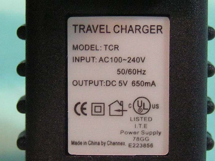
Q9L-0009
Jul 19, 2006Bluetooth Headset
Equipment Class
DSS - Part 15 Spread Spectrum Transmitter
Q9LGG01
Jun 03, 2004Bluetooth Headset
Equipment Class
DSS - Part 15 Spread Spectrum Transmitter
Q9LGG301
Jun 29, 2003BLUETOOTH HEADSET
Equipment Class
DSS - Part 15 Spread Spectrum Transmitter