Q9Z-PC5NR3-JVision Plate 60 Hand Held PC with Wireless LAN
Hitachi Keiyo Engineering and Systems, Ltd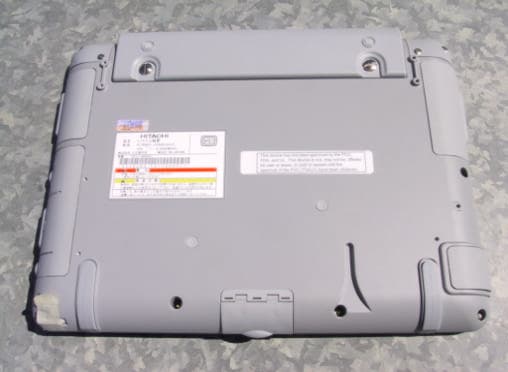
Click to zoom
Application Details
- Equipment Class
- DTS - Digital Transmission System
- Date of Grant
- Aug 26, 2003
- Application Purpose
- Original Equipment
- Date of Application
- Aug 26, 2003
- Equipment Note
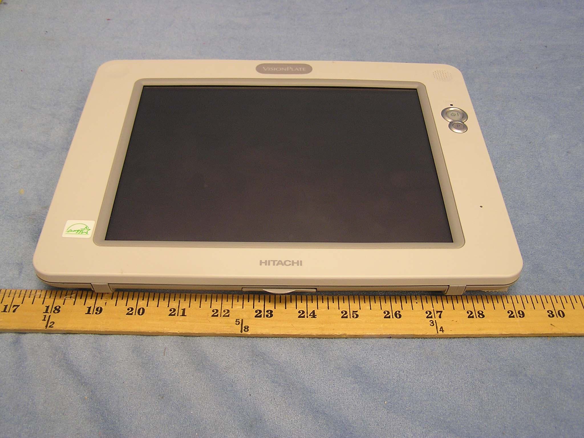
- Vision Plate 60 Hand Held PC with Wireless LAN
- Frequency Range
- 2412.00000000 - 2462.00000000
- Country
- Japan
Documents & Files
Document Text
Text extracted from the exhibit documents filed with the FCC. Open a document above to read the original.
Users Manual
VisionPlate ™ Model 60 USER MANUAL . Copyright © 2003 Hitachi Data Systems. All rights reserved. This publication contains information that is protected by copyright. No part of it may be reproduced, transmitted, transcribed, stored in a retrieval system, or translated into any language without permission from Hitachi Data Systems. Trademark Crusoe is a trademark of Transmeta Corporation. Microsoft, MS-DOS, and Windows are registered trademarks of Microsoft Corporation. IBM and PS/2 are trademarks of International Business Machines Corporation All trademarks, trade names and service marks used herein are the rightful property of their respective owners. 2 Table of Contents Disclaimer..................................................................................................................................................5 Section 1. Health and Safety....................................................................................................................6 1-1 Health and Safety Information..........................................................................................................6 • Introduction......................................................................................................................................6 • Vision Risk Factors...........................................................................................................................7 • Hand and Wrist Motor Risk Factors.................................................................................................7 • Body Support Risk Factors...............................................................................................................8 • Product..............................................................................................................................................8 • Main Battery Pack............................................................................................................................9 • Power Cord.......................................................................................................................................9 • AC Adapter.....................................................................................................................................10 • Liquid Crystal Display (LCD)........................................................................................................10 • Proper Treatment of Your Hitachi Product.....................................................................................11 1-2 Safety and Regulatory Information................................................................................................12 • FCC Part 15 Compliance Statement............................................................................................... 12 • Canadian EMI Compliance Statement............................................................................................12 • FCC Warning..................................................................................................................................12 • UL1604 Compliance Statement......................................................................................................13 • General Safety................................................................................................................................14 • Battery Safety.................................................................................................................................15 • Operation Safety.............................................................................................................................15 Section 2. Getting Started With Your VisionPlate...............................................................................16 2-1 Identifying Components.................................................................................................................16 • Overview........................................................................................................................................16 • Buttons and Lamps.........................................................................................................................16 • Left Side Connectors......................................................................................................................17 • Right Side Connectors....................................................................................................................17 • Cradle (optional).............................................................................................................................18 2-2 Setup...............................................................................................................................................19 • Direct-to-outlet Connection............................................................................................................19 • Desktop Use (with optional cradle)................................................................................................20 • Mobile Use.....................................................................................................................................21 2-3 Powering On and Off The Unit......................................................................................................22 • Powering On the Unit.....................................................................................................................22 • Powering Off the Unit....................................................................................................................22 Section 3. Using Your VisionPlate..........................................................................................................23 3-1 Using the Stylus..............................................................................................................................23 3-2 Touchscreen Calibration........…
Text truncated - open the document above for the full version.
Cover Letter(s)
Confidentiality Request 7/10/03 AmericanTCB 6731 Whittier Ave. McLean, VA 22101 FCC ID: O9Z-PC5NR3-J In regards the exhibits submitted in support of the application for FCC ID: O9Z- PC5NR3-J, please classify the following as confidential: • Schematics • Parts List • Block Diagram These exhibits contain technical information which Hitachi Keiyo Engineering and Systems, Ltd deems to be sensitive and proprietary. Therefore this information cannot be published. If this information were to be made public it could be used to the disadvantage of the applicant in the marketplace. Bob Cole President EMCE Engineering (Authorized Agent for Hitachi Keiyo Engineering and Systems, Ltd)
Cover Letter(s)
American Telecommunications Certification Body Inc. 6731 Whittier Ave, McLean, VA 22101 July 19, 2003 RE: Hitachi Keiyo Engineering and Systems LTD FCC ID: Q9Z-PC5NR3-J I have a few comments on this Application. 1.) Current FCC RF Exposure criteria assume that “Tablet PCs” can be used in the lap while persons are seated. This will necessitate a SAR test for any device with an RF Pout (conducted or radiated EIRP) above 60mW/f(GHz). This equates to a power of 24mW in the 2450MHz spread spectrum bands. If you can prove that the antennas are mounted greater than 2.5cm from all persons when used in the lap of a seated person then a looser limit of 120mW/f(GHz) would apply. I am unable to determine from the photographs where the antenna is located and it’s distance to the operator. A copy of the current TCB Exclusion List of July 2002 is included for your reference. FYI: Please note the specification sheet supplied on this card shows this is rated at 31.6mW (+15dBm). 2.) Please submit clearer and larger photographs for all interior views. Please be sure to include the underside of the main board as well. 3.) Please provide an RF Exposure exhibit – either SAR or MPE estimation - for this device as required by 15.247(b)(5). 4.) Current interpretation of RF Pout measurement procedure for RF Exposure finds spectrum analyzers too inaccurate for Pout testing – especially if SAR testing is possibly involved. Please provide more accurate power readings. The optimum way recognized by the Commission is to use the diode detector/signal generator substitution method as illustrated in a separate attachment. Be sure to check power across low, mid, and high channels at all applicable data rates. 5.) The Test Report appears to make multiple references to Bluetooth protocols and not exclusively 802.11b. This is confusing to the casual reader. Please review. 6.) Test Data for AC Powerline Conducted tests seem to be missing. As a service to your client. please remember to provide test data down to 150KHz. 7.) Peak and Average radiated values for the restricted band of 2483.5 to 2500MHz and 2310 to 2390MHz seem to be missing. Please provide this data. 8.) Test Setup photographs for AC Conducted and Radiated test configurations must be provided as a separate exhibit. This is an FCC requirement. Please supply. 9.) The manual has no instructions for users on how to minimize their RF Exposure. Moreover, I cannot provide for you specific language to be included in the manual because this language is dependent on the question of SAR testing. Please advise at your earliest opportunity. 10.) There is no Block Diagram which covers the wireless LAN card. Please supply a functional block diagram conforming to 2.1033(b)(5). 11.) The Label and Location photo is inadequate. Please supply a readable exhibit. William H. Graff President and Examining Engineer mailto: [email protected] The items indicated above must be submitted before processing can continue on the above referenced application. Failure to provide the requested information may result in application termination. Correspondence should be considered part of the permanent submission and may be viewed from the Internet after a Grant of Equipment Authorization is issued. Please do not respond to this correspondence using the email reply button. In order for your response to be processed expeditiously, you must submit your documents through the AmericanTCB.com website. Also, please note that partial responses increase processing time and should not be submitted. Any questions about the content of this correspondence should be directed to the sender.
Cover Letter(s)
American Telecommunications Certification Body Inc. 6731 Whittier Ave, McLean, VA 22101 August 14, 2003 RE: Hitachi Keiyo Engineering and Systems LTD FCC ID: Q9Z-PC5NR3-J I am missing responses to some of my questions from my July 19 request. Please review. There are also a couple new questions. 1.) Current interpretation of RF Pout measurement procedure for RF Exposure finds spectrum analyzers too inaccurate for Pout testing. Please provide more accurate power readings. The optimum way recognized by the Commission is to use the diode detector/signal generator substitution method as illustrated in a separate attachment. Be sure to check power across low, mid, and high channels at all applicable data rates. 2.) The Test Report appears to make multiple references to “hopping enabled” (Bluetooth?) protocols and not exclusively 802.11b. As an example please see pp. 6, 7, 8, and 9. Other instances may have occurred within the report. Please review and correct. 3.) Peak and Average radiated values for the restricted band of 2483.5 to 2500MHz and 2310 to 2390MHz seem to be missing. Please provide this data. Also, please show enough “overlap” in your Plots 15 and 16 to confirm the transmitter was tuned to 2412 MHz for the lower edge restricted band measurement and 2462 MHz for the upper edge restricted band measurement. 4.) Please be sure the Manual specifies that this transmitter must not be co-located with any other transmitters or antennas. 5.) The 6dB BW plots are incorrect. All other 802.11b devices show a 6dB BW of approximately 10MHz. Please correct. FYI: For clarity may I suggest using 5dB/division for your display. 6.) It also appears when comparing Plot 10 with Plots 11&12 that two different data rates were used. Please be sure to show worst case data rate for the 6dB BW measurement. 7.) Spectral Power Density, plots 4, 5, and 6, use incorrect test receiver settings. Please see 15.247(d). Your span of 50MHz would require a sweep time of over 16,666 seconds. A more realistic value is to show a 3MHz span with a 1000 second sweep time. William H. Graff President and Examining Engineer mailto: [email protected] The items indicated above must be submitted before processing can continue on the above referenced application. Failure to provide the requested information may result in application termination. Correspondence should be considered part of the permanent submission and may be viewed from the Internet after a Grant of Equipment Authorization is issued. Please do not respond to this correspondence using the email reply button. In order for your response to be processed expeditiously, you must submit your documents through the AmericanTCB.com website. Also, please note that partial responses increase processing time and should not be submitted. Any questions about the content of this correspondence should be directed to the sender.
External Photos
FCC ID: Q9Z-PC5NR3-J External Photos EUT Front View EUT Rear View
ID Label/Location Info
1. System unit 2. Patent label FCC ID: Q9Z-PC5NR3-J 3. UL1604 4. Labeling position (idea)
Internal Photos
Hitachi PC5NR3 Internal Photos Main PCB – Bottom Side Hitachi PC5NR3 Internal Photos Radio PCB – Top Side Hitachi PC5NR3 Internal Photos Radio PCB – Bottom Side Hitachi PC5NR3 Internal Photos Main PCB – Top side Hitachi PC5NR3 Internal Photos Bottom Cover EMI Coating Hitachi PC5NR3 Internal Photos LCD Display Hitachi PC5NR3 Internal Photos Antenna PCB - Top Hitachi PC5NR3 Internal Photos Antenna PCB – Bottom
Internal Photos
FCC ID: Q9Z-PC5NR3-J Internal Photos Bottom Cover Removed LCD Display with Cover Radio PCB Bottom Side Radio PCB Top Side Antenna PCB Bottom Side Antenna PCB Top Side System Main Board Bottom Cover Shielding
Operational Description
Data Sheet June 2002 Wireless LAN Mini PCI Type IIIA Card Introduction The Mini PCI Type IIIA Card is an 11 Mbits/s wireless networking card with a range of up to 550 m (1750 ft). With its small size, light weight, and low power consumption, it is ideally suited to integration in a wide range of OEM devices. The Mini PCI Card uses direct sequence spread spectrum (DSSS) technology, and implements DBPSK, DQPSK, and CCK modulation, as defined in the IEEE Æ 802.11b standard. This gives a very robust radio channel, which is made even better by the excellent receiver sensitivity and delay spread robustness. In environments with radio interference, the Mini PCI Card, because of its acknowledgment protocol and its option to be tuned to another frequency channel, continues to run. Superior echo path management makes it suitable for areas with a large delay spread, for example, warehouses. This reduces the number of cells required and, therefore, reduces the total cost of ownership. Security against eavesdropping is provided for by WEP using a 64-bit or 128-bit key. WEPplus prevents attacks that exploit weak keys. The 802.1x standard is also supported. The Mini PCI Card is complemented by drivers and networking tools for various versions of the Windows Æ operating system and for Linux. Agere provides extensive technical documentation on integration issues such as antenna design, customizing drivers, and management software. Features ! Automatic fallback: 11 Mbits/s, 5.5 Mbits/s, 2 Mbits/s, or 1 Mbit/s ! Low power consumption ! Automatic power management to reduce battery use ! Firmware image downloaded to card each time driver is loaded ! Easy integration into mobile and hand-held platforms, with freedom of design and antenna placement ! External antenna diversity ! WEPplusófully compatible with WEP, but avoiding the weaknesses ! Conforms to IEEE 802.11 and IEEE 802.11b specification ! Can be used in platform with multiple wireless LAN cards ! Interoperable with other IEEE 802.11b compliant systems ! Conforms to industry-standard mini PCI Card Type IIIA specification ! Compatible with Windows and Linux operating systems ! Microsoft Æ OIDs on all Windows drivers ! WHQL certification for all supported Windows operating systems Data Sheet Wireless LAN Mini PCI Type IIIA Card June 2002 2 Agere Systems Inc. Physical Dimensions/Packaging The Mini PCI Card has been designed to conform to the Mini PCI specification, as defined in Mini PCI Specification Rev 1.0. All dimensions in this section have a tolerance as permitted in the Mini PCI Specification. Dimensions: 59.75 mm x 50.95 mm x 5.0 mm Weight: 15 g 59.75 mm 30.45 mm 2.60 mm 50.95 mm 42.15 mm 41.4 mm REF MAIN REF AUX Figure 1. Mini PCI Card Dimensions Mechanically unique coax connectors for two external antennas. Shock and Vibration Resilience The Mini PCI Card has been developed for incorporation in other devices, and, as such, no shock and vibration tests for the card in isolation have been performed. Reliability MTTF 150,000 hours, based on workload of 2040 hours/year within operating conditions. Operating Conditions Operating Temperature Range 0 ∞C to 60 ∞C ambient temperature Relative Humidity When Operational 95% maximum (noncondensing) Barometric Pressure 740 hPa to 1050 hPa Data Sheet June 2002 Wireless LAN Mini PCI Type IIIA Card Agere Systems Inc. 3 Absolute Maximum Ratings Stresses in excess of the absolute maximum ratings can cause permanent damage to the device. These are absolute stress ratings only. Functional operation of the device is not implied at these or any other conditions in excess of those given in the operations sections of the data sheet. Exposure to absolute maximum ratings for extended periods can adversely affect device reliability. Parameter Description Storage Temperature Range ñ20 ∞C to +75 ∞C ambient temperature Relative Humidity During Storage 95% maximum (noncondensing) Barometric Pressure 740 hPa to 1050 hPa Electrical Specification Parameter Description Supply Voltage 3.3 Vdc from host (±0.2 V). Ripple Tolerance of Supply Voltage 120 mV ripple (measured peak-to-peak) with fundamental frequency ≤150 kHz. Load Capacitance of Supply Voltage ≤150 μF. Power-on Start-up time ≤600 ms after switching power supply on. (This includes a delay of max 500 ms for the Flash ROM power up sequence.) Doze to Receive Mode Start-up Time ≤75 ms. Transmissions are not allowed during this period. Power Consumption Doze mode Receive mode Transmit mode Typical for Mini PCI Card 16 mA 185 mA 285 mA Max for Mini PCI Card 45 mA 250 mA 350 mA Data Sheet Wireless LAN Mini PCI Type IIIA Card June 2002 4 Agere Systems Inc. RF Specification Parameter Description Frequency Range 2400 MHz to 2484 MHz Frequency Stability Within 25 kHz of nominal value Transmitter Output Power 15 dBm ± 2 dB Over-driving Levels Tolerated up to +17 dBm at the antenna connector Nominal Antenna Port Impedance 50 Ω Media Access Protocol CSMA/CA with ACK Direct-sequence spread spectrum CCK (11 Mbits/s and 5.5 Mbit/s) DQPSK (2 Mbits/s) Modulation Technique DBPSK (1 Mbit/s) Spreading 11-chip Barker sequence Data Rate Receiver Sensitivity (Bit Error Rate <0 ñ5 ) Delay spread robustness (FER <1%) 11 Mbits/s ñ82 dBm 65 ns 5.5 Mbits/s ñ87 dBm 225 ns 2 Mbits/s ñ91 dBm 400 ns 1 Mbit/s ñ94 dBm 500 ns Antenna Specification The Mini PCI Card is available in two variants as regards antenna diversity: on-board diversity switch, and external diversity switch. On-Board Diversity Switch This variant of the Mini PCI Card has connectors for two external passive antennas: MAIN and AUX. One of the antennas is used for transmission, and the DSP selects which of the two to use for reception, based on signal strength. The coax connectors for the antennas are mechanically unique, such that no off-the-shelf connector will fit (FCC requirement). Switch electronics for selection between the two antennas for reception of the stronger receive signal is provided onboard. External Diversity Switch Thi…
Text truncated - open the document above for the full version.
RF Exposure Info
Test Report S/N: 080503-403Q9Z Test Date(s): August 7, 2003 FCC SAR Evaluation © 2003 Celltech Labs Inc. 1 of 23 Celltech Labs Inc. declares under its sole responsibility that this device was found to be in compliance with the Specific Absorption Rate (SAR) RF exposure requirements specified in FCC 47 CFR §2.1093. The device was tested in accordance with the measurement standards and procedures specified in FCC OET Bulletin 65, Supplement C, Edition 01-01 (General Population / Uncontrolled Exposure). I attest to the accuracy of data. All measurements were performed by me or were made under my supervision and are correct to the best of my knowledge and belief. I assume full responsibility for the completeness of these measurements and vouch for the qualifications of all persons taking them. This test report shall not be reproduced partially, or in full, without the prior written approval of Celltech Labs Inc. The results and statements contained in this report pertain only to the device(s) evaluated. Russell Pipe Senior Compliance Technologist Celltech Labs Inc. DECLARATION OF COMPLIANCE SAR EVALUATION Test Lab CELLTECH LABS INC. Testing and Engineering Lab 1955 Moss Court Kelowna, B.C. Canada V1Y 9L3 Phone: 250-448-7047 Fax: 250-448-7046 e-mail: [email protected] web site: www.celltechlabs.com Applicant Information HITACHI DATA SYSTEMS 5402 Hellyer Avenue, MS 3882 San Jose, CA 95138 USA Rule Part(s): FCC 47 CFR §2.1093 Test Procedure(s): FCC OET Bulletin 65, Supplement C (01-01) FCC Device Classification: Part 15 Spread Spectrum Transmitter (DSS) FCC ID: Q9Z-PC5NR3-J Trade Name / Model: PC5NR3-XXXXXXXXX Device Type: PC Tablet with internal Agere Systems Mini-PCI DSSS WLAN Module Tx Frequency Range: 2412 - 2462 MHz Max. Output Power Tested: 15.4 dBm Conducted (2462 MHz) Modulation: DSSS Battery Type: Lithium-Ion 11.1V, 1.7Ah (Hitachi Model: PC-AB5900) Lithium-Ion 11.1V, 3.4Ah (Hitachi Model: PC-AB5910) Antenna Type: Dual Internal Max. SAR Measured: 0.572 W/kg (Top Side – Left Antenna – Standard Battery) Test Report S/N: 080503-403Q9Z Test Date(s): August 7, 2003 FCC SAR Evaluation © 2003 Celltech Labs Inc. 2 of 23 TABLE OF CONTENTS 1.0 INTRODUCTION..................................................................... 3 2.0 DESCRIPTION OF EUT............................................................ 3 3.0 SAR MEASUREMENT SYSTEM ............................................... 4 4.0 MEASUREMENT SUMMARY..................................................... 5 5.0 DETAILS OF SAR EVALUATION............................................... 6 6.0 EVALUATION PROCEDURES................................................... 7-8 7.0 SYSTEM PERFORMANCE CHECK............................................ 9 8.0 EQUIVALENT TISSUES........................................................... 10 9.0 SAR LIMITS........................................................................... 10 10.0 SYSTEM SPECIFICATIONS...................................................... 11 11.0 PROBE SPECIFICATION.......................................................... 12 12.0 SAM PHANTOM...................................................................... 12 13.0 DEVICE HOLDER.................................................................... 12 14.0 TEST EQUIPMENT LIST........................................................... 13 15.0 MEASUREMENT UNCERTAINTIES............................................ 14-15 16.0 REFERENCES........................................................................ 16 APPENDIX A - SAR MEASUREMENT DATA............................................. 17 APPENDIX B - SYSTEM CHECK DATA.................................................... 18 APPENDIX C - SYSTEM VALIDATION..................................................... 19 APPENDIX D - PROBE CALIBRATION.................................................... 20 APPENDIX E - MEASURED FLUID DIELECTRIC PARAMETERS................ 21 APPENDIX F - SAM PHANTOM CERTIFICATE OF CONFORMITY.............. 22 APPENDIX G - SAR TEST SETUP & EUT PHOTOGRAPHS........................ 23 Test Report S/N: 080503-403Q9Z Test Date(s): August 7, 2003 FCC SAR Evaluation © 2003 Celltech Labs Inc. HITACHI DATA SYSTEMS. FCC ID: Q9Z-PC5NR3-J3 of 23 PC Tablet with Mini-PCI DSSS WLAN Module (2412-2462MHz) This measurement report demonstrates that the HITACHI DATA SYSTEMS Model: PC5NR3 PC Tablet FCC ID: Q9Z- PC5NR3-J with internal Agere Systems Mini-PCI DSSS WLAN Module complies with the RF exposure requirements specified in FCC 47 CFR §2.1093 (see reference [1]) for the General Population environment. The test procedures described in FCC OET Bulletin 65, Supplement C, Edition 01-01 (see reference [2]) were employed. A description of the product, operating configuration, detailed summary of the test results, methodology and procedures used in the evaluation, equipment used, and the various provisions of the rules are included within this test report. FCC Rule Part(s) 47 CFR §2.1093 Test Procedure FCC OET Bulletin 65, Supplement C (01-01) FCC Device Classification Part 15 Spread Spectrum Transmitter (DSS) Device Type PC Tablet with internal Agere Systems Mini-PCI DSSS WLAN Module FCC ID Q9Z-PC5NR3-J Model Hitachi PC5NR3-XXXXXXXXX Serial No. Z9A65C010 Tx Frequency Range 2412 - 2462 MHz Max. RF Output Power Tested 15.4 dBm Conducted (2462 MHz) Antenna Type PCB Diversity Battery Type(s) Lithium-Ion 11.1V, 1.7Ah (Hitachi Model: PC-AB5900) Lithium-Ion 11.1V, 3.4Ah (Hitachi Model: PC-AB5910) 1.0 INTRODUCTION 2.0 DESCRIPTION of Equipment Under Test (EUT) Test Report S/N: 080503-403Q9Z Test Date(s): August 7, 2003 FCC SAR Evaluation © 2003 Celltech Labs Inc. HITACHI DATA SYSTEMS. FCC ID: Q9Z-PC5NR3-J4 of 23 PC Tablet with Mini-PCI DSSS WLAN Module (2412-2462MHz) Celltech Research SAR measurement facility utilizes the Dosimetric Assessment System (DASY™) manufactured by Schmid & Partner Engineering AG (SPEAG™) of Zurich, Switzerland. The DASY system is comprised of the robot controller, computer, …
Text truncated - open the document above for the full version.
RF Exposure Info
Test Report S/N: 080503-403Q9Z Test Date(s): August 7, 2003 FCC SAR Evaluation © 2003 Celltech Labs Inc. HITACHI DATA SYSTEMS. FCC ID: Q9Z-PC5NR3-J 17 of 23 PC Tablet with Mini-PCI DSSS WLAN Module (2412-2462MHz) APPENDIX A - SAR MEASUREMENT DATA Hitachi Data Systems FCC ID: Q9Z-PC5NR3-J SAM Phantom; Flat Section; Position: (0°,0°) Probe: ET3DV6 - SN1387; ConvF(4.60,4.60,4.60); Crest factor: 1.0 Muscle 2450 MHz: σ = 1.99 mho/m ε r = 50.1 ρ = 1.00 g/cm 3 Coarse: Dx = 15.0, Dy = 15.0, Dz = 10.0 Back of PC Tablet - Left Side Antenna 0.0 cm Separation Distance from Back of PC Tablet to Planar Phantom Hitachi Data Systems Model: PC5NR3 with Agere Systems Mini-PCI WLAN Module Standard Li-Ion Battery Model: PC-AB5900 (1.7 Ah) DSSS Mode Channel 6 [2437 MHz] Conducted Power: 15.30 dBm Ambient Temp: 25.5°C; Fluid Temp: 23.8°C Date Tested: August 7, 2003 Coarse Scan to Show Antenna Edge of EUT Bottom SAR Tot [mW/g] 8.00E-3 2.40E-2 4.00E-2 5.60E-2 7.20E-2 08/07/03 Celltech Labs Inc. Hitachi Data Systems FCC ID: Q9Z-PC5NR3-J SAM Phantom; Flat Section; Position: (0°,0°) Probe: ET3DV6 - SN1387; ConvF(4.60,4.60,4.60); Crest factor: 1.0 Muscle 2450 MHz: σ = 1.99 mho/m ε r = 50.1 ρ = 1.00 g/cm 3 Coarse: Dx = 15.0, Dy = 15.0, Dz = 10.0 Cube 5x5x7 Powerdrift: -0.17 dB SAR (1g): 0.0698 mW/g, SAR (10g): 0.0382 mW/g Back of PC Tablet - Left Side Antenna 0.0 cm Separation Distance from Back of PC Tablet to Planar Phantom Hitachi Data Systems Model: PC5NR3 with Agere Systems Mini-PCI WLAN Module Standard Li-Ion Battery Model: PC-AB5900 (1.7 Ah) DSSS Mode Channel 6 [2437 MHz] Conducted Power: 15.30 dBm Ambient Temp: 25.5°C; Fluid Temp: 23.8°C Date Tested: August 7, 2003 Coarse Scan to Evaluate Cube Scan SAR Tot [mW/g] 8.30E-3 2.49E-2 4.15E-2 5.81E-2 7.47E-2 08/07/03 Celltech Labs Inc. Hitachi Data Systems FCC ID: Q9Z-PC5NR3-J SAM Phantom; Flat Section; Position: (0°,0°) Probe: ET3DV6 - SN1387; ConvF(4.60,4.60,4.60); Crest factor: 1.0 Muscle 2450 MHz: σ = 1.99 mho/m ε r = 50.1 ρ = 1.00 g/cm 3 Coarse: Dx = 15.0, Dy = 15.0, Dz = 10.0 Back of PC Tablet - Left Side Antenna 0.0 cm Separation Distance from Back of PC Tablet to Planar Phantom Hitachi Data Systems Model: PC5NR3 with Agere Systems Mini-PCI WLAN Module Standard Li-Ion Battery Model: PC-AB5900 (1.7 Ah) DSSS Mode Channel 6 [2437 MHz] Conducted Power: 15.30 dBm Ambient Temp: 25.5°C; Fluid Temp: 23.8°C Date Tested: August 7, 2003 Coarse Scan to Show Remaining Half of Bottom (Back of LCD Display) SAR Tot [mW/g] 7.00E-4 2.10E-3 3.50E-3 4.90E-3 6.30E-3 08/07/03 Celltech Labs Inc. Hitachi Data Systems FCC ID: Q9Z-PC5NR3-J SAM Phantom; Flat Section; Position: (90°,0°) Probe: ET3DV6 - SN1387; ConvF(4.60,4.60,4.60); Crest factor: 1.0 Muscle 2450 MHz: σ = 1.99 mho/m ε r = 50.1 ρ = 1.00 g/cm 3 Coarse: Dx = 15.0, Dy = 15.0, Dz = 10.0 Cube 5x5x7 Powerdrift: -0.04 dB SAR (1g): 0.572 mW/g, SAR (10g): 0.252 mW/g Top of PC Tablet - Left Side Antenna 0.0 cm Separation Distance from Top of PC Tablet to Planar Phantom Hitachi Data Systems Model: PC5NR3 with Agere Systems Mini-PCI WLAN Module Standard Li-Ion Battery Model: PC-AB5900 (1.7 Ah) DSSS Mode Channel 6 [2437 MHz] Conducted Power: 15.30 dBm Ambient Temp: 25.5°C; Fluid Temp: 23.8°C Date Tested: August 7, 2003 SAR Tot [mW/g] 5.73E-2 1.72E-1 2.87E-1 4.01E-1 5.16E-1 08/07/03 Celltech Labs Inc. Hitachi Data Systems FCC ID: Q9Z-PC5NR3-J SAM Phantom; Flat Section Probe: ET3DV6 - SN1387; ConvF(4.60,4.60,4.60); Crest factor: 1.0 Muscle 2450 MHz: σ = 1.99 mho/m ε r = 50.1 ρ = 1.00 g/cm 3 Z-Axis Extrapolation at Peak SAR Location Top of PC Tablet - Left Side Antenna 0.0 cm Separation Distance from Top of PC Tablet to Planar Phantom Hitachi Data Systems Model: PC5NR3 with Agere Systems Mini-PCI WLAN Module Standard Li-Ion Battery Model: PC-AB5900 (1.7 Ah) DSSS Mode Channel 6 [2437 MHz] Conducted Power: 15.30 dBm Ambient Temp: 25.5°C; Fluid Temp: 23.8°C Date Tested: August 7, 2003 08/07/03 Celltech Labs Inc. 0.0 0.2 0.4 0.6 0.8 1.0 1.2 1.4 0102030405060708090100110120130140150 SAR tot [mW/g] […
Text truncated - open the document above for the full version.
Contact Information
Applicant
Sam Law(Engineering Services Manager)
sam.law@hds,com408-970-7706
Technical Contact
EMCE EngineeringBob Cole
[email protected]510 490 4307
44366 S. Grimmer Blvd · Fremont, California · United States
Test Firm
Universal Compliance LabsBob Cole
Technical Specifications
| # | Rule Parts | Frequency Range | Power Output |
|---|---|---|---|
| 1 | 15C | 2.41 GHz - 2.46 GHz | 35.00 mW |
Other Applications from Hitachi Keiyo Engineering and Systems, Ltd
Q9Z-PC5NR3-J2
Oct 07, 2004Wireless Tablet PC with 802.11b/g
Equipment Class
DTS - Digital Transmission System
Q9Z-PC5NR3-J1
Apr 29, 2004Wireless Tablet
Equipment Class
DTS - Digital Transmission System