QB8LT5GTMicrowave Outdoor Unit
DragonWave Inc.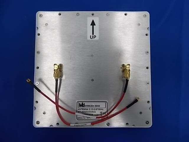
Click to zoom
Application Details
- Equipment Class
- DTS - Digital Transmission System
- Date of Grant
- Jun 11, 2014
- Application Purpose
- Original Equipment
- Date of Application
- Jun 11, 2014
- Equipment Note
- Microwave Outdoor Unit
- Frequency Range
- 5745.00000000 - 5825.00000000
- Company
- DragonWave Inc.
- Country
- Canada
Documents & Files
Document Text
Text extracted from the exhibit documents filed with the FCC. Open a document above to read the original.
Users Manual
LITE, R1.0 Installation Guide Revision 2, updated in May, 2014 Notice This document contains DragonWave proprietary information. Use, disclosure, copying or distribution of any part of the information contained herein, beyond that for which it was originally furnished, requires the written permission of DragonWave Inc. The information in this document is subject to change without notice and relates only to the product defined in the introduction of this document. DragonWave intends that information contained herein is, to the best of its knowledge, correct and accurate. However, any/all liabilities associated with the use or accuracy of the information contained herein must be defined in a separate agreement between DragonWave and the customer/user. Copyright © DragonWave Inc. 2014. All rights reserved. Table of Contents 1 Preface .................................................................................................... 5 1.1 History of changes ........................................................................................................... 5 1.2 Scope of the document .................................................................................................... 5 1.3 Intended audience ............................................................................................................ 5 1.4 Document structure .......................................................................................................... 5 2 Before installation .................................................................................. 7 2.1 Precautions ...................................................................................................................... 7 2.2 Needed parts .................................................................................................................... 8 3 Mounting Steps .................................................................................... 11 3.1 Mounting on the wall ...................................................................................................... 11 3.2 Mounting on the pole (1’ ~ 1.75’ diameter) .................................................................... 13 3.3 Mounting on the pole (1.75’ ~ 3’ diameter) .................................................................... 13 3.4 Mounting on the pole (3’ ~ 4.55’) ................................................................................... 14 4 Cabling .................................................................................................. 17 4.1 Ethernet cable connection in the doghouse ................................................................... 17 4.1.1 P+E connection ................................................................................................................... 17 4.1.2 PoE+ connection ................................................................................................................. 18 4.2 External antenna connection .......................................................................................... 18 5 Preface 1 Preface 1.1 History of changes The history of changes is shown in the following table: 1.2 Scope of the document This document provides the guidance to install and commission the LITE system. INFO This document only concerns LITE system release 1.0 (LITE R1.0 in short) without specific statements in the context. 1.3 Intended audience This document is prepared for the use of technicians who are responsible for the system installation and commissioning. WARNING! PERSONS HANDLING THIS EQUIPMENT MAY BE EXPOSED TO HAZARDS WHICH COULD RESULT IN PHYSICAL INJURY! IT IS THEREFORE MANDATORY TO CARE- FULLY READ AND UNDERSTAND THIS DOCUMENT. 1.4 Document structure The document is comprised of the following chapters. TA BLE 1. History of changes RevisionUpdatesUpdate date 11st revisionAugust, 2013 2In Chapter 2, some warnings are added to meed the requirements.May, 2014 TA BLE 2. Document structure ChapterTitleSubject Chapter 1PrefaceProvides an introduction on who and how to use this docu- ment. Chapter 2Before installationProvides some information about the preparations and pre- cautions before the installation. Chapter 3Mounting stepsProvides the mounting steps. Chapter 4CablingProvides the cabling guidance. Preface 6 7 Before installation 2 Before installation 2.1 Precautions The radiation emitted by the antenna is low-power radiation and does not exceed the safety regula- tions. If the radio is operated without antenna, the safety limit is exceeded near the waveguide open- ings. WARNING! THE INSTALLATION MUST ONLY BE PERFORMED BY A QUALIFIED TECHNICIAN. WARNING! RISK OF PERSONAL INJURY. THIS PRODUCT MAY NEED TO BE INSTALLED ON A HIGH-RISE STRUCTURE SUCH AS A TOWER OR MAST. WHEN INSTALLING THE PRODUCT, WEAR A SAFETY HARNESS AND OTHER RELEVANT PROTECTIVE GEAR. IN ADDITION, FOLLOW ALL OCCUPATIONAL HEALTH AND SAFETY REGULATIONS APPLICABLE TO THE INSTALLATION. WARNING! HAZARDOUS ENERGY EXISTS WITHIN THE DEVICE. ALWAYS BE CAREFUL TO AVOID ELECTRIC SHOCK. WARNING! THE EQUIPMENT SHOULD BE LOCATED IN RESTRICTED ACCESS LOCATIONS. WARNING! WHEN INSTALLING THE UNIT, ALWAYS MAKE THE GROUND CONNECTION FIRST AND DISCONNECT IT LAST. WARNING! THE DEVICE MUST BE CONNECTED PERMANENTLY TO THE PROTECTION GROUND BEFORE AN OPERATION. THE CROSS-SECTIONAL AREA OF THE PROTECTIVE GROUND CONDUCTOR MUST BE AST LEAST 18AWG. WARNING! THE DEVICE MUST BE FIXED SECURELY ON RELIABLE OBJECTS. WARNING! REINFORCED INSULATION OR DOUBLE INSULATION MUST BE PROVIDED TO ISO- LATE DC SOURCE FROM AC MAIN SUPPLY WHICH COMPLIES WITH REQUIREMENTS IN IEC 60950-1 BASED SAFETY STANDARDS. The following restrictions must be considered before installing the equipment: • The weather conditions must be taken into account when installing the equipment. The maximum and minimum temperatures at the installation location must remain within the acceptable range. For cable installation temperatures, refer to the cable m…
Text truncated - open the document above for the full version.
Users Manual
Harmony Lite, R1.0 Operation and Maintenance Guide Revision 2, updated in May, 2014 Document Number: PM-000003-01-EN draft Notice This document contains DragonWave proprietary information. Use, disclosure, copying or distribution of any part of the information contained herein, beyond that for which it was originally furnished, requires the written permission of DragonWave Inc. The information in this document is subject to change without notice and relates only to the product defined in the introduction of this document. DragonWave intends that information contained herein is, to the best of its knowledge, correct and accurate. However, any/all liabilities associated with the use or accuracy of the information contained herein must be defined in a separate agreement between DragonWave and the customer/user. Copyright © DragonWave Inc. 2014. All rights reserved. draft Table of Contents 1 Preface .................................................................................................... 9 1.1 History of changes ........................................................................................................... 9 1.2 Scope of the document .................................................................................................... 9 1.3 Intended audience ............................................................................................................ 9 1.4 Document structure .......................................................................................................... 9 2 Commissioning .................................................................................... 11 2.1 Before commissioning .................................................................................................... 11 2.2 Commission steps .......................................................................................................... 11 2.2.1 Logging in ............................................................................................................................ 11 2.2.2 Setting the management IP ................................................................................................. 12 2.2.3 Setting the management VLAN ........................................................................................... 13 2.2.4 Setting the radio parameters ............................................................................................... 14 3 System configuration ........................................................................... 19 3.1 System home ................................................................................................................. 19 3.2 System inventory ............................................................................................................ 19 3.3 Software inventory ......................................................................................................... 20 3.4 Software management ................................................................................................... 21 3.5 Configuration management ............................................................................................ 21 3.6 P+E output .....................................................................................................................22 draft 3.7 Licensing .........................................................................................................................22 3.8 SNTP ..............................................................................................................................23 3.9 Synchronization ..............................................................................................................23 4 Wireless radio configuration ............................................................... 25 4.1 Wireless radio #1 configuration ......................................................................................25 4.2 Received Signal Strength Indication ...............................................................................25 4.3 Modulation and ACM ......................................................................................................26 4.4 Tx power and Adaptive Transmit Power Control (ATPC) ...............................................27 5 Ethernet configuration ......................................................................... 29 5.1 Ports ...............................................................................................................................29 5.2 Speed .............................................................................................................................29 5.3 VLAN management ........................................................................................................30 5.4 QoS scheduler ................................................................................................................30 5.5 Traffic criteria ..................................................................................................................31 5.6 IP priority .........................................................................................................................31 5.7 VLAN PRI priority ............................................................................................................32 5.8 Port priority .....................................................................................................................32 5.9 Aging time .......................................................................................................................33 5.10 Static Unicast FDB ........................................................................................................33 5.11 All FDB ..........................................................................................................................33 6 Management ...................................................................…
Text truncated - open the document above for the full version.
Cover Letter(s)
DragonWave Inc. Date: May 29, 2014 Federal Communications Commission Authorization and Evaluation Division FCC ID: QB8LT5GT ATTESTATION FCC ID: QB8LT5GT Product: Microwave Outdoor Unit Model: Harmony Lite 5GHz We don't provide any controls or software to allow operation outside the USA frequency band when we sell this product in USA. Sincerely, __________________ Name: Jerry Potera Position: Regulatory Approvals DragonWave Inc.
Cover Letter(s)
DragonWave Inc. Declaration of Authorization We Name: DragonWave Inc. Address: 600-411 Legget Drive, Kanata ON K2K 3C9, CANADA Declare that: Name Representative of agent: Robin Wu Agent Company name: MRT Technology (Suzhou) Co., Ltd Address: D8 Building, Youxin Industrial Park, No.2 Tian'edang Rd., Wuzhong Economic Development Zone, City: Suzhou Country China is authorized to apply for Certification of the following product(s): Product description: Microwave Outdoor Unit Type designation: Harmony Lite 5GHz Trademark: on our behalf. Date: May 29, 2014 Name: Jerry Potera Signature:
Cover Letter(s)
DragonWave Inc. 600-411 Legget Drive, Ottawa, ON, Canada K2K 3C9 (t) 613.599.9991 (f) 613.599.4225 www.dragonwaveinc.com 29 May 2014 Equipment Autorisation Division Federal Communications Commission 7435 Oakland Mills Road Columbia, MD 21046 FCC ID: QB8LT5GT Product Name: Microwave Outdoor Unit Request for Confidentiality Pursuant to Sections 0.457 and 0.459 of the commission’s rules, we hereby request that the following documents be held confidential: Schematics Block diagram Parts List Layouts and drawings Operational Description These materials contain trade secrets and proprietary information and are not customarily released to the public. The public disclosure of this information might be harmful to the company and provide unjustified benefits to our competitors. Dated this 29 th Day of May 20 14 By: Jerry Potera Signature Printed Title: Regulatory Approvals On behalf of : DragonWave Inc. Telephone: 613-599-9991 x.2267
Cover Letter(s)
Non-SDR (Software Defined Radio) Cover Letter Date: June 03, 2014 Refer to KDB 442812 D01 SDR apps Guide v02r02. The following six questions can be used for determining if a radio can elect to be, or must be an SDR. 1. Can the RF parameters of the device be altered through software? Yes - go to 2. No, not an SDR Yes 2. Can third parties not permitted by the Commission through specific filings modify, configure, or load different software, or make configuration settings to operate the device or host hardware radio frequency parameters (frequency range, modulation type, maximum output power or other radio parameters) in any other way than granted (or expected to be granted)? Yes, must be an SDR. No - go to 3. No 3. Is the device capable of operating in any other in any other way than granted, or will be, granted? Yes, - go to 4. No - go to 5. No 4. Is this a Part 15 client Device as defined in Section 15.202 (as opposed to a master device)? Yes, qualifies as a part 15 client devices - go to 5. No, must be an SDR. 5. Does the manufacturer elect SDR? Yes, elects to be an SDR. No, Not an SDR No Final conclusion: According to the first and second questions reply, we can confirm this Microwave Outdoor Unit must be a Non-SDR. The equipment can only support one exclusive regulation; this regulation can be activated by license based on the rules of the countries where it is installed. Without the regulation enabled by license, the radio interfaces are not allowed to be used for respecting the local regulation. The hardware devices will be locked to the activated regulatory domain and can’t be modified by any third party through configuration changes or software upgrades. The software also does not permit the configuration of any radio parameters (Frequency channel, channel bandwidth, modulation types and TX power etc.) by the user that would violate the activated regulatory domain policies. Sincerely, ---------------------------------------------------------- Name: Jerry Potera Title: Regulatory Approvals DragonWave Inc.
External Photos
1 of 9 External Photo (1) EUT Photo (2) EUT Photo (3) EUT Photo (4) EUT Photo (5) EUT Photo (6) EUT Photo (7) EUT Photo (8) EUT Photo (9) EUT Photo (10) EUT Photo (11) EUT Photo (12) EUT Photo (13) EUT Photo (Antenna S-Wave 55-10-22D-SMA) (14) EUT Photo (Antenna S-Wave 55-10-22D-SMA) (15) EUT Photo (Antenna S-Wave 55-10-22D-SMA) (16) EUT Photo (Antenna MT-485053/SVH/A) (17) EUT Photo (Antenna MT-485053/SVH/A) (18) EUT Photo (Antenna MT-485053/SVH/A)
ID Label/Location Info
Label Label Location
Internal Photos
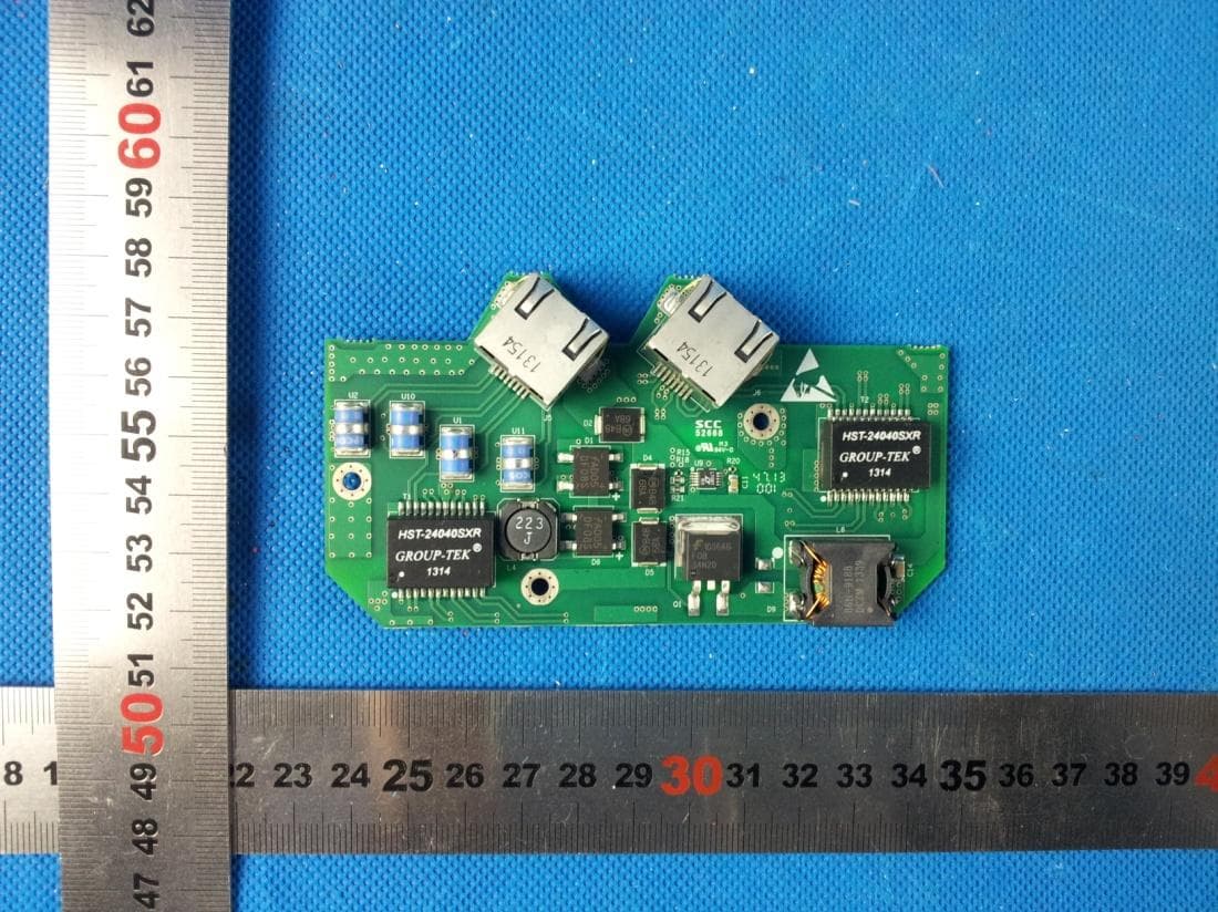
1 of 11 Internal Photo (1) EUT Photo (2) EUT Photo (3) EUT Photo (4) EUT Photo (5) EUT Photo (6) EUT Photo (7) EUT Photo (8) EUT Photo (9) EUT Photo (10) EUT Photo (11) EUT Photo (12) EUT Photo (13) EUT Photo (14) EUT Photo (Antenna S-Wave 55-10-22D-SMA) (15) EUT Photo (Antenna S-Wave 55-10-22D-SMA) (16) EUT Photo (Antenna S-Wave 55-10-22D-SMA) (17) EUT Photo (Antenna S-Wave 55-10-22D-SMA) (18) EUT Photo (Antenna MT-485053/SVH/A) (19) EUT Photo (Antenna MT-485053/SVH/A) (20) EUT Photo (Antenna MT-485053/SVH/A) (21) EUT Photo (Antenna MT-485053/SVH/A)
RF Exposure Info
MRT Technology (Suzhou) Co., Ltd Report No.: 1405RSU03502 Phone: +86-512-66308358 Report Version: V01 Fax: +86-512-66308368 Issue Date: 05-30-2014 Web: www.mrt-cert.com FCC ID: QB8LT5GT Page Number: 1 of 4 RF Exposure Evaluation Declaration FCC ID: QB8LT5GT APPLICANT: DragonWave Inc. Application Type: Certification Product: Microwave Outdoor Unit Model No.: Harmony Lite 5GHz FCC Classification: Digital Transmission System (DTS) Reviewed By : ( Robin Wu ) Approved By : ( Marlin Chen ) The test results relate only to the samples tested. The test results shown in the test report are traceable to the national/international standards through the calibration of the equipment and evaluated measurement uncertainty herein. The test report shall not be reproduced except in full without the written approval of MRT Technology (Suzhou) Co., Ltd. Report No.: 1405RSU03502 FCC ID: QB8LT5GT Page Number: 2 of 4 Revision History Report No. Version Description Issue Date 1405RSU03502 Rev. 01 Initial report 05-30-2014 Report No.: 1405RSU03502 FCC ID: QB8LT5GT Page Number: 3 of 4 1. RF Exposure Evaluation 1.1. Limits According to FCC 1.1310: The criteria listed in the following table shall be used to evaluate the environment impact of human exposure to radio frequency (RF) radiation as specified in 1.1307(b) LIMITS FOR MAXIMUM PERMISSIBLE EXPOSURE (MPE) Frequency Range (MHz) Electric Field Strength (V/m) Magnetic Field Strength (A/m) Power Density (mW/cm 2 ) Average Time (Minutes) (A) Limits for Occupational/ Control Exposures 300-1500 -- -- f/300 6 1500-100,000 -- -- 5 6 (B) Limits for General Population/ Uncontrolled Exposures 300-1500 -- -- f/1500 6 1500-100,000 -- -- 1 30 f= Frequency in MHz Calculation Formula: P d = (P out *G)/(4*pi*r 2 ) Where P d = power density in mW/cm 2 P out = output power to antenna in mW G = gain of antenna in linear scale Pi = 3.1416 r = distance between observation point and center of the radiator in cm P d is the limit of MPE, 1mW/cm². If we know the maximum gain of the antenna and the total power input to the antenna, through the calculation, we will know the distance r where the MPE limit is reached. Report No.: 1405RSU03502 FCC ID: QB8LT5GT Page Number: 4 of 4 1.2. Test Result of RF Exposure Evaluation Product Microwave Outdoor Unit Test Item RF Exposure Evaluation Antenna Gain: The maximum Gain measured in fully anechoic chamber is 23.5dBi for 5GHz in logarithm scale. For 5G ISM Band: Test Mode Frequency Band (MHz) Maximum Average output power (dBm) Limit of Power Density S(mW/cm²) Safety Distance (cm) 20MHz BW 5745 ~ 5825 19.32 1 39.03 40MHz BW 5755 ~ 5795 19.11 1 38.10 CONCULISON: The Safety Distance of this equipment was 39.03 cm. The End
Test Report
MRT Technology (Suzhou) Co., Ltd Report No.: 1405RSU03501 Phone: +86-512-66308358 Report Version: V01 Fax: +86-512-66308368 Issue Date: 05-30-2014 Web: www.mrt-cert.com FCC ID: QB8LT5GT Page Number: 1 of 50 FCC ID: QB8LT5GT APPLICANT: DragonWave Inc. Application Type: Certification Product: Microwave Outdoor Unit Model No.: Harmony Lite 5GHz Brand Name: FCC Classification: Digital Transmission System (DTS) FCC Rule Part(s): Part 15.247 Test Procedure(s): ANSI C63.10-2009, KDB 558074 D01v03r01 KDB 662911 D01v02r01, KDB 662911 D02v01 Test Date: January 13 ~ 21, 2014 MEASUREMENT REPORT FCC PART 15.247 Reviewed By : ( Robin Wu ) Approved By : ( Marlin Chen ) The test results relate only to the samples tested. This equipment has been shown to be capable of compliance with the applicable technical standards as indicated in the measurement report and was tested in accordance with the measurement procedures specified in KDB 558074 D01v03r01. Test results reported herein relate only to the item(s) tested. The test report shall not be reproduced except in full without the written approval of MRT Technology (Suzhou) Co., Ltd. Report No.: 1405RSU03501 FCC ID: QB8LT5GT Page Number: 2 of 50 Revision History Report No. Version Description Issue Date 1405RSU03501 Rev. 01 Initial report 05-30-2014 Report No.: 1405RSU03501 FCC ID: QB8LT5GT Page Number: 3 of 50 CONTENTS Description Page §2.1033 General Information ......................................................................................................... 5 1. INTRODUCTION ..................................................................................................................... 6 1.1. Scope ........................................................................................................................... 6 1.2. MRT Test Location ....................................................................................................... 6 2. PRODUCT INFORMATION ..................................................................................................... 7 2.1. Equipment Description .................................................................................................. 7 2.2. Description of Available Antennas and Configurations .................................................. 7 2.3. Frequency / Channel Opreation .................................................................................... 8 2.4. Data Rate Verification ................................................................................................... 9 2.5. Device Capabilities ....................................................................................................... 9 2.6. Test Configuration ........................................................................................................ 9 2.7. Test Software ............................................................................................................. 10 2.8. EMI Suppression Device(s)/Modifications ................................................................... 10 2.9. Labeling Requirements ............................................................................................... 10 3. DESCRIPTION OF TEST ....................................................................................................... 11 3.1. Evaluation Procedure .................................................................................................. 11 3.2. AC Line Conducted Emissions .................................................................................... 11 3.3. Radiated Emissions .................................................................................................... 12 4. ANTENNA REQUIREMENTS ................................................................................................ 13 5. TEST EQUIPMENT CALIBRATION DATA ............................................................................ 14 6. MEASUREMENT UNCERTAINTY ......................................................................................... 15 7. TEST RESULT ...................................................................................................................... 16 7.1. Summary .................................................................................................................... 16 7.2. 6dB Bandwidth Measurement ..................................................................................... 17 7.2.1. Test Limit ................................................................................................................ 17 7.2.2. Test Procedure used ............................................................................................... 17 7.2.3. Test Setting ............................................................................................................. 17 7.2.4. Test Setup ............................................................................................................... 17 7.2.5. Test Result .............................................................................................................. 18 7.3. Output Power Measurement ....................................................................................... 21 7.3.1. Test Limit ................................................................................................................ 21 7.3.2. Test Procedure Used .............................................................................................. 21 7.3.3. Test Setting ............................................................................................................. 21 Report No.: 1405RSU03501 FCC ID: QB8LT5GT Page Number: 4 of 50 7.3.4. Test Setup ............................................................................................................... 22 7.3.5. Test Result of Peak Output Power .......................................................................... 23 7.3.6. Test Result of Average Output Power (Reporting Only) ...............…
Text truncated - open the document above for the full version.
Test Setup Photos
1 of 2 Test Setup Photo Description: Radiated Emission Test Setup for 9kHz ~ 30MHz Description: Radiated Emission Test Setup for 30MHz ~ 1GHz Description: Radiated Emission Test Setup for 1GHz ~ 18GHz Description: Radiated Emission Test Setup for 18GHz ~ 40GHz
Contact Information
Applicant
Jerry Potera(Regulatory Approvals)
Technical Contact
DragonWave Inc.Lei Shi
[email protected]+86-13918052865
No.1801, Homgmei Road, XuHui District · Shanghai · China
Non-Technical Contact
DragonWave Inc.Rosario Varchetta
[email protected]+86-18602118067
Test Firm
MRT Technology (Suzhou) Co., LtdWu Jian
[email protected]86-512-66308358
Technical Specifications
| # | Rule Parts | Frequency Range | Power Output |
|---|---|---|---|
| 1 | 15C | 5.75 GHz - 5.83 GHz | 887.00 mW |
Other Applications from DragonWave Inc.
QB8LT3G
Oct 14, 2014Microwave Outdoor Unit
Equipment Class
TNB - Licensed Non-Broadcast Station Transmitter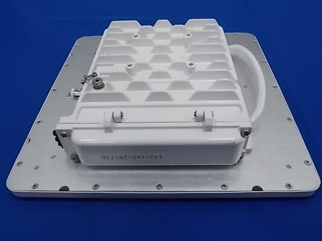
QB8LT5G
Sep 28, 2014Microwave Outdoor Unit
Equipment Class
NII - Unlicensed National Information Infrastructure TX
QB8HCP58UL
Feb 04, 2013Horizon Compact Plus CPHP58B1X
Equipment Class
DXX - Part 15 Low Power Communication Device Transmitter
QB8HC-24UL
Mar 03, 2008Horizon Compact, CUSP24UFC
Equipment Class
DXX - Part 15 Low Power Communication Device Transmitter
QB8-DWR24-000002
Feb 25, 200424GHz AirPair Point-Point Radio Unit
Equipment Class
DXT - Part 15 Low Power Transceiver, Rx Verified