QCIIDS665PT1SMART Board 6000S and 6000S Pro Series Interactive Displays
SMART Technologies Inc.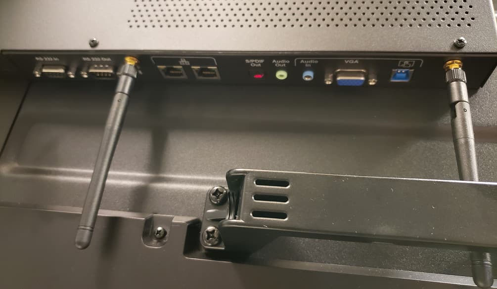
Click to zoom
Application Details
- Equipment Class
- DXX - Part 15 Low Power Communication Device Transmitter
- Date of Grant
- Jan 09, 2020
- Application Purpose
- Original Equipment
- Date of Application
- Jan 09, 2020
- Equipment Note
- SMART Board 6000S and 6000S Pro Series Interactive Displays
- Frequency Range
- 13.56000000 - 13.56000000
- Company
- SMART Technologies Inc.
- Country
- Canada
Documents & Files
Document Text
Text extracted from the exhibit documents filed with the FCC. Open a document above to read the original.
Users Manual
Wasthisdocumenthelpful? smarttech.com/docfeedback/171415 SMART Board® 6000S and 6000S Pro series interactivedisplays USERGUIDE SBID-6265S|SBID-6275S|SBID-6286S|SBID-6265S-PW|SBID-6275S-PW|SBID-6286S-PW|SBID-6265S-P|SBID- 6275S-P|SBID-6286S-P| smarttech.com/kb/171415 Learnmore ThisguideandotherresourcesforSMART Board6000Sand6000SPro seriesinteractivedisplaysareavailableintheSupportsectionofthe SMART website(smarttech.com/support).ScanthisQR codetoviewthese resourcesonyourmobiledevice. Licenses ThetermsHDMIandHDMIHigh-DefinitionMultimediaInterface,andtheHDMIlogoaretrademarksorregisteredtrademarksofHDMILicensingLLCintheUnited Statesandothercountries. TheBluetoothwordmarkisownedbytheBluetoothSIG,Inc.andanyuseofsuchmarksbySMART Technologies ULCisunderlicense. Trademarknotice SMARTBoard,SMARTNotebook,SMARTMeetingPro,PenID,HyPrTouch,ObjectAwareness,Silktouch,ToolSense,smarttech,theSMARTlogoandallSMART taglinesaretrademarksorregisteredtrademarksofSMARTTechnologiesULCintheU.S.and/orothercountries.TheBluetoothwordmarkisownedbythe BluetoothSIG,Inc.andanyuseofsuchmarksbySMARTTechnologiesULCisunderlicense.TheAdoptedTrademarksHDMI,HDMIHigh-DefinitionMultimedia Interface,andtheHDMILogoaretrademarksorregisteredtrademarksofHDMILicensingAdministrator,Inc.intheUnitedStatesandothercountries.Allother third-partyproductandcompanynamesmaybetrademarksoftheirrespectiveowners. Copyrightnotice ©2019 SMART Technologies ULC.Allrightsreserved.Nopartofthispublicationmaybereproduced,transmitted,transcribed,storedinaretrievalsystemor translatedintoanylanguageinanyformbyanymeanswithoutthepriorwrittenconsentofSMART Technologies ULC.Informationinthismanualissubjecttochange withoutnoticeanddoesnotrepresentacommitmentonthepartofSMART. Thisproductand/orusethereofiscoveredbyoneormoreofthefollowingU.S.patents: www.smarttech.com/patents November22,2019 ismarttech.com/kb/171415 Importantinformation NOTE RefertotheSMART Board6000Sand6000SProseriesinteractivedisplaysinstallationand maintenanceguide(smarttech.com/kb/171414)forimportantinformationaboutinstallingand maintainingthedisplay. WARNING lDonotopenordisassemblethedisplay.Youriskelectricalshockfromthehighvoltage insidethecasing.Openingthecasingalsovoidsthewarranty. lDonotstand(orallowchildrentostand)onachairtotouchthesurfaceofthedisplay. lToreducetheriskoffireorelectricshock,donotexposethedisplaytorainormoisture. lDonotinsertobjectsinsidethecabinetventilationholes,becausetheycouldtouch dangerousvoltagepointsandcauseelectricshock,fireorproductdamagewhichmaynot becoveredbythewarranty. lDonotplaceheavyobjectsonthepowercable.Damagetothecablecouldcauseshock, fireorproductdamagewhichmaynotbecoveredbythewarranty. lIftheglassisbroken,donottouchtheliquidcrystal.Topreventinjury,handleglass fragmentswithcarewhendisposingofthem. lDisconnectthedisplay’spowercablefromthewalloutletandseekassistancefrom qualifiedservicepersonnelifanyofthefollowingoccur: o Thepowercableorplugisdamaged o Liquidisspilledintothedisplay o Objectsfallintothedisplay o Thedisplayisdropped o Structuraldamage,suchascracking,occurs o Thedisplaybehavesunexpectedlywhenyoufollowoperatinginstructions IMPORTANTINFORMATION iismarttech.com/kb/171415 ENERGY STAR® ENERGYSTARisthegovernment-backedsymbolforenergyefficiency,providingsimple, credible,andunbiasedinformationthatconsumersandbusinessesrelyontomakewell-informed decisions.ENERGYSTAR-certifiedproductsarethesimplechoiceforenergyefficiency,makingit easyforconsumersandbusinessestomakepurchasesthatsavethemmoneyandprotectthe environment.TheU.S.EPAensuresthateachproductthatearnsthelabelisindependently certifiedtodeliverthequality,performance,andsavingsthatusershavecometoexpect. PendingitscertificationasanENERGYSTARcertifiedsignagedisplay,yourdisplaydelivers excellentperformanceandsavings.However,changingsomesettingsmayincreaseenergy consumptionbeyondthelimitsrequiredforENERGYSTARcertification.Forexample,increased brightnessandcontrastwillincreasepowerconsumption. Pleaseconsidertheenvironmentwhenyouchoosenon-ENERGYSTARsettings. FederalCommunicationCommission interferencestatement FCC Supplier’sDeclarationofConformity 47CFR§2.1077ComplianceInformation UniqueIdentifier:IDS665-1,IDS675-1,IDS686-1 ResponsibleParty–U.S.ContactInformation SMARTTechnologiesInc. 24014thAve,3rdFloor Seattle,WA98121 [email protected] ThisdevicecomplieswithPart15oftheFCCRules.Operationissubjecttothefollowingtwoconditions: 1.Thisdevicemaynotcauseharmfulinterference,and 2.thisdevicemustacceptanyinterferencereceived,includinginterferencethatmaycauseundesiredoperation. NOTE ThisequipmenthasbeentestedandfoundtocomplywiththelimitsforaClassAdigitaldevice,pursuanttopart15ofthe FCCRules.Theselimitsaredesignedtoprovidereasonableprotectionagainstharmfulinterferencewhentheequipmentis operatedinacommercialenvironment.Thisequipmentgenerates,uses,andcanradiateradiofrequencyenergyand,ifnot installedandusedinaccordancewiththeinstructionmanual,maycauseharmfulinterferencetoradiocommunications. Operationofthisequipmentinaresidentialareaislikelytocauseharmfulinterferenceinwhichcasetheuserwillbe requiredtocorrecttheinterferenceathisownexpense. IMPORTANTINFORMATION iiismarttech.com/kb/171415 CAUTION Anychangesormodificationsnotexpresslyapprovedbythepartyresponsibleforcompliancecouldvoidtheuser’s authoritytooperatethisequipment. Restriction Operationsinthe5.15-5.25GHzbandarerestrictedtoindoorusageonly. IEEE802.11bor802.11goperationofthisproductintheUSAisfirmwarelimitedtochannels1through13. Radiationexposurestatement ThisequipmentcomplieswithFCCradiationexposurelimitssetforthforanuncontrolledenvironment.Thisequipmentshould beinstalledandoperatedwithminimumdistanceof20cmbetweentheantennaofthisdeviceandallnearbypersons.This transmittermustnotbeco-locatedoroperatedinconjunctionwithanyotherantennaortransmitter. Innovation,ScienceandEconomicDevelopment Canadastatement ThisdevicecomplieswithICES-003oftheInnovation,ScienceandEconomicDevelopmentCanadaRules.Operationissubject tothefollowingtwoconditions: 1.Thisdevicemaynotcauseharmfu…
Text truncated - open the document above for the full version.
Cover Letter(s)
SMART Technologies ULC 3636 Research Road NW Calgary, AB T2L 1Y1 CANADA Phone 403.245.0333 Fax 403.228.2500 [email protected] www.smarttech.com Federal Communications Commission Authorization & Evaluation Division 7435 Oakland Mills Road, Columbia, MD 21046 Dec. 20, 2019 Confidentiality Request regarding application for certification of FCC ID: QCIIDS665PT1. Pursuant to Sections 0.457 and 0.459 of the Commission’s Rules, we hereby request confidential treatment of information accompanying this application as outlined below: Exhibit Type File Name Block Diagram Theory of Operation Schematic and BOM QCIIDS665PT1_IDS665-1_Panel_BlkDia.pdf QCIIDS665PT1_IDS665-1_Panel_OpDes.pdf QCIIDS665PT1_IDS665-1_Panel_Schem.pdf The above materials contain trade secrets and proprietary information not customarily released to the public. The public disclosure of these materials may be harmful to the applicant and provide unjustified benefits to its competitors. The applicant understands that pursuant to Section 0.457 of the Rules, disclosure of this application and all accompanying documentation will not be made before the date of the Grant for this application. Pursuant to DA04-1705 June 15, 2004 of the Commission’s public notice, we also request temporary confidential treatment (45 days) of information accompanying this application as outlined below: Exhibit Type File Name Internal Pictures QCIIDS665PT1_IDS665-1_Panel_IntPho.pdf Sincerely, Todd Gallagher Senior Regulatory Specialist SMART Technologies Inc. [email protected]
Cover Letter(s)
SMART Technologies ULC 3636 Research Road NW Calgary, AB T2L 1Y1 CANADA Phone 403.245.0333 Fax 403.228.2500 [email protected] www.smarttech.com Federal Communications Commission Authorization & Evaluation Division 7435 Oakland Mills Road, Columbia, MD 21046 Date: December 20, 2019 SUBJECT: FCC Application for QCIIDS665PT1 To Whom It May Concern: We, the undersigned, hereby authorize Adiseshu Nyshadham at DVT Solutions Inc. on our behalf, to apply to the Federal Communications Commission on our equipment. Any and all acts carried out by Adiseshu Nyshadham on our behalf shall have the same effect as acts of our own. This is to advise that we are in full compliance with the Anti- Drug Abuse Act. We, the applicant, are not subject to a denial of federal benefits pursuant to Section 5301 of the Anti-Drug Act of 1988, 21 USC853a, and no party to the application is subject to a denial of federal benefits pursuant to that section. Regards, Todd Gallagher Senior Regulatory Specialist SMART Technologies Inc. [email protected]
External Photos
Pictures Regulatory Model: IDS665-1 FCCID: QCIIDS665PT1 IC:4302A-IDS665PT1 Front View Back View Left Hand Side View (Controller) Side Connectors Bottom Connectors
ID Label/Location Info
Label location
ID Label/Location Info
IDS665-1 Label FCCID: QCIIDS665P1 IC:4302A-IDS665P1
Internal Photos
Pictures Regulatory Model: IDS665-1 FCCID: QCIIDS665PT1 IC: 4302A-IDS665P1 Internal view Pen Tray Antenna Power Supply (Component View) Power Supply (Soldering View) Casper Scaler PCB (Component View) Casper Scaler PCB (Solder View) Kansas Touch Controller (Component Side) Kansas Touch Controller (Solder Side) Kansas Pen Tray ISM Board (Component Side) Kansas Pen Tray ISM Board (Solder Side) Tray Antennas (Component Side) Tray Antennas (Solder Side)
Test Report
Applied Test Lab Inc. Page 2 of 44 Report #: S002E047-43-T Date of Issue: 2020-01-08 Table of Contents 1.0 General...............................................................................................................................................................................3 1.1 Purpose........................................................................................................................................................................3 1.2 Relevant Standards and References........................................................................................................................3 1.3 Performance Requirement........................................................................................................................................3 1.4 Measurement Uncertainty.........................................................................................................................................3 1.5 Test Results Summary...............................................................................................................................................4 1.6 Test Facility Information...........................................................................................................................................4 1.7 Client Information...................................................................................................................................................... 4 2.0Test Sample Information...................................................................................................................................................5 2.1 Equipment Under Test (EUT)....................................................................................................................................5 2.2 Support Equipment and Details...............................................................................................................................6 2.3 I/O Ports and Details................................................................................................................................................... 6 2.4 I/O Cable Descriptions...............................................................................................................................................6 3.0 Test Facilities......................................................................................................................................................................7 3.1 Semi-Anechoic Chamber Test Site Description......................................................................................................8 3.2 A diagram of the Semi-Anechoic Chamber Test Site...........................................................................................10 3.3 Test Equipment List..................................................................................................................................................11 4.0 Test Setup Description...................................................................................................................................................13 4.1 EUT System Block Diagram and Support Equipment.........................................................................................13 4.2 Test Setup Photographs 20dB Bandwidth.............................................................................................................14 4.3 Test Setup Photographs AC Power Line Conducted Emission (0.15MHz – 30MHz).....................................15 4.4a Test Setup Photographs Radiated Spurious Emissions (0.009MHz – 30MHz)..............................................16 4.4b Test Setup Photographs Radiated Spurious Emissions (30MHz – 1000MHz)...............................................17 4.5 Test Setup Photographs Frequency Stability........................................................................................................18 5.0 Test Methodology............................................................................................................................................................ 19 5.1 Method of measurement of 20dB Bandwidth.......................................................................................................19 5.2 Method of measurement of AC Power Line Conducted Emission....................................................................19 5.3 Method of measurement of Radiated Spurious Emissions.................................................................................20 5.4 Method of measurement of Frequency Stability..................................................................................................23 6.0 Test Results....................................................................................................................................................................... 24 6.1 FCC 15.225(a) 20dB Bandwidth..............................................................................................................................24 6.2 FCC 15.203 Antenna Requirement..........................................................................................................................26 6.3 FCC 15.207 AC Power Line Conducted Emission................................................................................................27 6.4 FCC 15 225(a) – (c) Radiated Spurious Emissions................................................................................................32 6.5 FCC 15.209, 15 225(d) Radiated Spurious Emissions...........................................................................................34 6.6 FCC 15 225(e) Frequency Stability..........................................................................................................................40 7.0 Appendix A – Test Sample Description......................................................................................................................42 8.0 Appendi…
Text truncated - open the document above for the full version.
Test Setup Photos
1.1Test Setup Photographs 20dB Bandwidth Applicable Figure 1.1 - Test Setup - Front View Figure 1.2 - Test Setup - Side View 1.2Test Setup Photographs AC Power Line Conducted Emission (0.15MHz – 30MHz) Applicable Figure 1.3 - Test Setup - Front View Figure 1.4 - Test Setup - Side View 1.3aTest Setup Photographs Radiated Spurious Emissions (0.009MHz – 30MHz) Applicable Figure 1.5a - Test Setup - Front View Figure 1.6a - Test Setup - Side View 1.3bTest Setup Photographs Radiated Spurious Emissions (30MHz – 1000MHz) Applicable Figure 1.5b - Test Setup - Front View Figure 1.6b - Test Setup - Side View 1.4Test Setup Photographs Frequency Stability Applicable Figure 1.7 - Test Setup - Power system Figure 1.8 - Test Setup - Measurement system
Contact Information
Applicant
Nicole McMillan(Manager, Systems Design, Regulatory and Compliance)
Test Firm
APPLIED TEST LAB INC.ADISESHU NYSHADHAM
[email protected]403-590-8570
Technical Specifications
| # | Rule Parts | Frequency Range | Power Output |
|---|---|---|---|
| 1 | 15C | 13.56 MHz - 13.56 MHz | - |
Other Applications from SMART Technologies Inc.

QCI-AATMOD1
Jul 29, 2026The SAT-1 SoundFlow Audio Broadcasting System is a Bluetooth Low Energy (BLE) audio broadcasting device designed to transmit audio over Bluetooth Auracast or Unicast.
Equipment Class
DTS - Digital Transmission System
QCI-PQRMOD3
May 22, 2026PQR-3
Equipment Class
DTS - Digital Transmission System
QCI-CBQRMOD3
May 21, 2026CBQR-3
Equipment Class
DXX - Part 15 Low Power Communication Device Transmitter
QCI-CRXMOD1
Oct 01, 2024CRXMOD1
Equipment Class
DTS - Digital Transmission System
QCI-SKIWB800D3
Oct 17, 2023BT/BLE/WiFi 6 radio module
Equipment Class
DSS - Part 15 Spread Spectrum Transmitter