QCJSPDR650Short Pulse Digital Radar
Zebra Technologies Corporation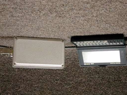
Click to zoom
Application Details
- Equipment Class
- UWB - Ultra Wideband Transmitter
- Date of Grant
- Jan 13, 2003
- Application Purpose
- Original Equipment
- Date of Application
- Nov 03, 2002
- Equipment Note
- Short Pulse Digital Radar
- Frequency Range
- 6020.00000000 - 6699.00000000
- Country
- United States
Documents & Files
Document Text
Text extracted from the exhibit documents filed with the FCC. Open a document above to read the original.
Users Manual
SPIDER-650 Short Pulse Digital RADAR User’s Guide M M ULTISPECTRAL ULTISPECTRAL S S OLUTIONS, OLUTIONS, I I NC. NC. A Tradition of Excellence in Innovation A Tradition of Excellence in Innovation 2 Note 1: General Conditions of operation (FCC 15.5) This device complies with Part 15 of the FCC Rules. Operation is subject to the following two conditions: (1) this device may not cause harmful interference, and (2) this device must accept any interference received, including interference that may cause undesired operation. Note 2: Modifications (FCC 15.21) Changes or modifications to this equipment not expressly approved by Multispectral Solutions, Inc. may void the user's authority to operate this equipment. Note 3: Fields of Use (FCC 15.511 and 15.513) Operation of this device is restricted to law enforcement, fire and rescue officials, scientific research institutes, public utilities, commercial mining companies, construction companies and industrial entities. Operation by any other party is a violation of 47 U.S.C. 301 and could subject the operator to serious legal penalties. 3 Chapter 1 – INTRODUCTION Overview The SPIDER-650 is intended for determining the presence of objects that are within a 50-foot line-of-sight of the unit. The unit has a resolution of 1 foot with a maximum range of 50 feet. Installation The SPIDER-650 unit can be placed anywhere as long as the antennae are facing outward towards the open space of detection. The antennae are located on the side with the elevated plastic facing. The only components required are an external cable (see Figure 1) and power supply. The cable should be 9-pin female on both ends with one end having two terminals for distributing power to the SPIDER-650 unit. Figure 1 below shows banana leads as an example of a way to use an external power supply as the source. Battery terminal leads may also be used to power the unit as long as the battery can supply about 1 watt of power at its operating voltage (see Table 1). 9-pin Female (to Terminal) 9-pin Female (to RADAR Unit) Banana Leads (to Battery or Power Supply) Figure 1 - Communication / Power Cable Table 1 - Pin Description of Terminal-Side 9-Pin Female Pin Number Pin Name Description 1 GND Grounded 2 RD Received Data 3 TD Transmitted Data 4 N.C. No Connect 5 GND Grounded 6 Power Input DC Power – Approximately 200mA @ +5V. Input DC Voltage can range from +3V to +30V. 7 N.C. No Connect 8 N.C. No Connect 9 Power Input DC Power – Approximately 200mA @ +5V. Input DC Voltage can range from +3V to +30V. 4 Table 2 - Pin Description of RADAR-Side 9-Pin Female Pin Number Pin Name Description 1 GND Ground 2 Serial_Out RS-232 Output 3 Serial_In RS-232 Input 4 GND Ground 5 GND Ground 6 POWER_IN Input DC Power – Approximately 200mA @ +5V. Input DC Voltage can range from +3V to +30V. 7 Loop Connected to Pin 8 8 Loop Connected to Pin 7 9 POWER_IN Input DC Power – Approximately 200mA @ +5V. Input DC Voltage can range from +3V to +30V. 1 5 6 9 Figure 2 – Communication Port Location Chapter 2 – BASIC SETUP This chapter describes the process for setting up a terminal window on a user’s computer. The below procedure assumes the user is running Windows 2000. Since other versions of Windows may deviate slightly from the following procedure, the user should check the operating system user’s manual for proper terminal setup procedures. HyperTerminal Setup To setup a HyperTerminal window under Windows 2000, adhere to the following procedure. STEP 1: Navigate to the Programs -> Accessories -> Communications folder and select the HyperTerminal icon. You should see a window similar to the one shown in Figure 3. Type a name for your HyperTerminal Session. The example below uses the “SPIDER-650” name. Once you have typed a name, click the OK button. 5 Figure 3 - Connection Description Window STEP 2: Determine which serial port the SPIDER-650 unit is attached to and enter it in the “Connect To” box shown below. Then click the OK button. Figure 4 - Serial Port Selection STEP 3: You should see the Port Settings dialog box come up next. Enter the settings exactly as they appear in Figure 5. Click the OK button when you are finished. Figure 5 - Serial Port Settings 6 STEP 4: Check the terminal settings window by navigating to the File -> Properties window and clicking the Settings tab. Make sure the properties are exactly as they appear in Figure 6. Figure 6 - Terminal Properties Powering the Unit Once the HyperTerminal setup is complete, applying power to the terminals will activate the unit. The HyperTerminal window should appear similar to Figure 7. This figure shows what the user will see in the HyperTerminal window on cycling power. Figure 7 - Initial Terminal Screen after Applied Power The screen displays the eight options available to the user. The most common option is the ‘g’ option. This will force the SPIDER-650 to transmit 5 consecutive pulses and recover and display the respective returns. Each of the 5 series of 50 returns is captured using a different sensitivity level on the receiver. Therefore, each row of asterisks on the HyperTerminal window displays a set of 50 returns received at a certain sensitivity level. The rows are arranged such that the first row of returns is captured at the least sensitive levels, while the last row of 50 returns is the most sensitive of the set. This display is illustrated in Figure 8 showing a target found at bin 13 at the 7 most sensitive setting. Typing the character ‘g’ on the terminal’s keyboard will place the user in this mode. Figure 8 - Terminal Screen after Executing 'g' Menu Item Aiming the Unit For best results, the unit should be aimed so that the white-faced plastic front is perpendicular to the line-of-sight between the unit and the target. Chapter 3 – ADVANCED MENU OPTIONS There are seven other advanced options available to the user if a custom software interface is to be used. DAC Menu Item The DAC Menu is the menu that allows the user to change sensitivity level…
Text truncated - open the document above for the full version.
External Photos
Spider 650 with Terminal Interface Spider 650 Front (C-band Patch Antenna) Spider 650 Back
ID Label/Location Info
Multispectral Solutions, Inc. Model: Spider-650 FCC ID: QCJSPDR650 This equipment complies with Part 15 of FCC rules. Operation is subject to the following conditions: (1) This device may not cause harmful interference; (2) This device must accept any interference received, including interference that may cause undesired operation; and (3) Operation of this device is restricted to law enforcement, fire and rescue officials, scientific research institutes, public utilities, commercial mining companies, construction companies and industrial entities. Operation by any other party is a violation of 47 U.S.C. 301 and could subject the operator to serious legal penalties. Enclosure back LABEL
Internal Photos
Spider 650 Side (RS-232/Power Interface) Spider 650 Inside Spider 650 Digital Side
Operational Description
Theory of Operation Spider-650is a lightweight, portable RADARdevice which utilizes ultra wideband (UWB) short-pulse technology to determine the pres- ence of, and the precise distance to, a target by measuring the round- trip time-of-flight of the transmitted pulse to the target and back. Spider-650can accurately determine the range to targets within a 50 foot distance from the unit, with a measurement accuracy of ± 1 foot. Spider-650provides a simple RS-232 or RS-485 interface for external control and monitoring. SPIDER-650 Features Specifications MULTISPECTRAL SOLUTIONS, INC. A Tradition of Excellence in Innovation ?OPERATESAT6.35 GHZUNDERNEWLYAPPROVEDFCC PART15 SUBPARTF ?SIMPLEASCIICONTROLANDMONITORINGINTERFACE ?UNITISPORTABLEANDLIGHTWEIGHT. WEIGHSONLY16 OUNCES. ?USESINDUSTRYSTANDARDRS-232 ORRS-485 COMMUNICATIONSLINK. ?ACCEPTSWIDERANGEOFDC INPUTPOWEROPTIONS(3.0 TO30.0 V). ?RADIOTECHNOLOGYULTRAWIDEBAND(UWB) ?FREQUENCYOFOPERATION6.35 GHZ ?INSTANTANEOUSBANDWIDTH700 MHZ ?PULSEREPETITIONRATE30 HZ ?TRANSMITTEROUTPUTPOWERFCCPART15.511 & 15.513 COMPLIANT ?RECEIVERSENSITIVITYNOMINAL-72 DBM@ 6 DBSNR ?RANGE50 FEET ?RANGERESOLUTIONS1 FOOT ?ANTENNA+14 DBIDUALWIDEBANDPATCH ?OPERATINGVOLTAGE3.0 VDC TO30.0 VDC ?CURRENTCONSUMPTION250 MA@ 5.0 VDC ?OPERATINGTEMPERATURERANGE0 TO+70°C ?DIMENSIONS6.375 X3.625 X3.5 INCHES(162 X92 X89 MM) Contact Rob Mulloy at (301) 528-1745 or [email protected] for OEMlicensing information
Test Report
The Nation's First Licensed Nationally Recognized Testing Laboratory Conceil canadien des nomes Organisme de certification accedite Standards Council of Canada Accredited Certification Organization TM MET Laboratories, Inc. Safety Certification - EMI - Telecom Environmental Simulation 914 WEST PATAPSCO AVENUE !! BALTIMORE, MARYLAND 21230-3432 !! PHONE (410) 354-3300 !! FAX (410) 354-3313 November 5, 2002 Multispectral Solutions, Inc. 202 Perry Parkway Gaithersburg, MD 20874 Reference:SPIDER 650 FCC ID: QCJSPDR650 Dear Mr. Robert Fontana: Enclosed is the EMC Test Report for the Multispectral Solutions, Inc. SPIDER 650. The Multispectral Solutions, Inc. SPIDER 650 was tested to the requirements of the FCC Rules and Regulations, Part 15 Subpart F, of Title 47 of the CFR, for a Part 15 Ultra-Wideband Device. Thank you for using the testing services of MET Laboratories. If you have any questions regarding these results or if MET can be of further assistance to you, please feel free to contact me. We appreciate your business and look forward to working with you again soon. Kindest Regards, MET LABORATORIES, INC. Marianne T. Bosley Documentation Department Enclosures: (\Multispectral Solutions, Inc.\EMC12906-FCC511.rpt) DOCTEM-23 Jan 02 Certificates and reports shall not be reproduced except in full, without the written permission of MET Laboratories, Inc. While use of the National Voluntary Laboratory Accreditation Program (NVLAP) letters or the NVLAP Logo in this report reflects the MET Accreditation under the NVLAP Program, these letters, logo, or Statements do not claim product endorsement by NVLAP or any Agency of the U.S. Government. Multispectral Solutions, Inc.SPIDER 650FCC ID: QCJSPDR650 November 5, 2002 Electro-Magnetic Compatibility Test Report for the Multispectral Solutions, Inc. SPIDER 650 Tested Under FCC Part 15 Subpart F Section 15.511 Title 47 of the CFR for Ultra-Wideband Operation MET REPORT: EMC12906-FCC511 November 5, 2002 PREPARED FOR: Multispectral Solutions, Inc. 202 Perry Parkway Gaithersburg, MD 20874 PREPARED BY: MET Laboratories, Inc. 914 West Patapsco Avenue Baltimore, Maryland 21230-3432 Copyright 2002, MET Laboratories, Inc. This report shall not be reproduced except in full, without the express written consent of MET Laboratories, Inc., nor shall this report, or any copy thereof be provided to a competitor of MET Laboratories, Inc. Multispectral Solutions, Inc.SPIDER 650FCC ID: QCJSPDR650 November 5, 2002 MET Report: EMC12906-FCC511 Draft1Copyright 2002, MET Laboratories, Inc.Page i of v Electro-Magnetic Compatibility Test Report for the Multispectral Solutions, Inc. SPIDER 650 Tested Under FCC Part 15 Subpart F Section 15.511 Title 47 of the CFR for Ultra-Wideband Operation MET REPORT: EMC12906-FCC511 November 5, 2002 PREPARED FOR: Multispectral Solutions, Inc. 202 Perry Parkway Gaithersburg, MD 20874 ______________________________________________________________ Christopher R. Harvey, DirectorMarianne T. Bosley Electromagnetic Compatibility TestingReport Writer Engineering Statement: The measurements shown in this report were made in accordance with the procedures indicated, and the emissions from this equipment were found to be within the limits applicable. I assume full responsibility for the accuracy and completeness of these measurements, and for the qualifications of all persons taking them. It is further stated that upon the basis of the measurements made, the equipment tested is capable of operation in accordance with the requirements of Part 15, Subpart F, Section 15.511, of the FCC Rules under normal use and maintenance. ___________________________________________ Liming XuGregory M. Czumak Project EngineerProject Engineer Multispectral Solutions, Inc.SPIDER 650FCC ID: QCJSPDR650 November 5, 2002 MET Report: EMC12906-FCC511 Draft1Copyright 2002, MET Laboratories, Inc.Page ii of v Table of Contents I. Executive Summary..........................................................................1 A.Purpose of Test....................................................................2 B.Executive Summary................................................................2 II. General...................................................................................4 A.Test Site.........................................................................5 B.Description of Test Sample..........................................................5 C.General Test Setup.................................................................5 D.Mode of Operation.................................................................5 E.Modifications.....................................................................8 F.Disposition of Test Sample...........................................................8 III. Electromagnetic Compatibility Antenna Requirements..............................................9 A.Antenna Evaluation Criteria.........................................................10 IV. Electromagnetic Compatibility Emissions Requirements............................................11 A.AC Line Conducted Emissions.......................................................12 B.UWB Bandwidth.................................................................15 C.Operational Limitations............................................................17 D.Cease Operation Provision Requirements...............................................18 E.Average Radiated Emissions - Broadband..............................................19 F.Average Radiated Emissions - Narrowband.............................................26 G.Peak Radiated Emissions...........................................................31 V. Labeling & Instructional Manual Requirements...................................................33 VI. Test Equipment...........................................................................36 VII. Certification Information - 47 CFR Part 2......................................................38 …
Text truncated - open the document above for the full version.
Test Report
TO:Reviewing Engineer DATE:5 November 2002 The newest Test Report was submitted to reflect new plot formats (more legible than in the first report submitted). Marianne Bosley The Nation's First Licensed Nationally Recognized Testing Laboratory Conceil canadien des nomes Organisme de certification accedite Standards Council of Canada Accredited Certification Organization TM MET Laboratories, Inc. Safety Certification - EMI - Telecom Environmental Simulation 914 WEST PATAPSCO AVENUE !! BALTIMORE, MARYLAND 21230-3432 !! PHONE (410) 354-3300 !! FAX (410) 354-3313 November 5, 2002 Multispectral Solutions, Inc. 202 Perry Parkway Gaithersburg, MD 20874 Reference:SPIDER 650 FCC ID: QCJSPDR650 Dear Mr. Robert Fontana: Enclosed is the EMC Test Report for the Multispectral Solutions, Inc. SPIDER 650. The Multispectral Solutions, Inc. SPIDER 650 was tested to the requirements of the FCC Rules and Regulations, Part 15 Subpart F, of Title 47 of the CFR, for a Part 15 Ultra-Wideband Device. Thank you for using the testing services of MET Laboratories. If you have any questions regarding these results or if MET can be of further assistance to you, please feel free to contact me. We appreciate your business and look forward to working with you again soon. Kindest Regards, MET LABORATORIES, INC. Marianne T. Bosley Documentation Department Enclosures: (\Multispectral Solutions, Inc.\EMC12906-FCC511.rpt) DOCTEM-23 Jan 02 Certificates and reports shall not be reproduced except in full, without the written permission of MET Laboratories, Inc. While use of the National Voluntary Laboratory Accreditation Program (NVLAP) letters or the NVLAP Logo in this report reflects the MET Accreditation under the NVLAP Program, these letters, logo, or Statements do not claim product endorsement by NVLAP or any Agency of the U.S. Government. Multispectral Solutions, Inc.SPIDER 650FCC ID: QCJSPDR650 November 5, 2002 Electro-Magnetic Compatibility Test Report for the Multispectral Solutions, Inc. SPIDER 650 Tested Under FCC Part 15 Subpart F Section 15.511 Title 47 of the CFR for Ultra-Wideband Operation MET REPORT: EMC12906-FCC511 November 5, 2002 PREPARED FOR: Multispectral Solutions, Inc. 20300 Century Boulevard Gaithersburg, MD 20874 PREPARED BY: MET Laboratories, Inc. 914 West Patapsco Avenue Baltimore, Maryland 21230-3432 Copyright 2002, MET Laboratories, Inc. This report shall not be reproduced except in full, without the express written consent of MET Laboratories, Inc., nor shall this report, or any copy thereof be provided to a competitor of MET Laboratories, Inc. Multispectral Solutions, Inc.SPIDER 650FCC ID: QCJSPDR650 November 5, 2002 MET Report: EMC12906-FCC511 Draft1Copyright 2002, MET Laboratories, Inc.Page i of v Electro-Magnetic Compatibility Test Report for the Multispectral Solutions, Inc. SPIDER 650 Tested Under FCC Part 15 Subpart F Section 15.511 Title 47 of the CFR for Ultra-Wideband Operation MET REPORT: EMC12906-FCC511 November 5, 2002 PREPARED FOR: Multispectral Solutions, Inc. 20300 Century Boulevard Gaithersburg, MD 20874 ______________________________________________________________ Christopher R. Harvey, DirectorMarianne T. Bosley Electromagnetic Compatibility TestingReport Writer Engineering Statement: The measurements shown in this report were made in accordance with the procedures indicated, and the emissions from this equipment were found to be within the limits applicable. I assume full responsibility for the accuracy and completeness of these measurements, and for the qualifications of all persons taking them. It is further stated that upon the basis of the measurements made, the equipment tested is capable of operation in accordance with the requirements of Part 15, Subpart F, Section 15.511, of the FCC Rules under normal use and maintenance. ___________________________________________ Liming XuGregory M. Czumak Project EngineerProject Engineer Multispectral Solutions, Inc.SPIDER 650FCC ID: QCJSPDR650 November 5, 2002 MET Report: EMC12906-FCC511 Draft1Copyright 2002, MET Laboratories, Inc.Page ii of v Table of Contents I. Executive Summary..........................................................................1 A.Purpose of Test....................................................................2 B.Executive Summary................................................................2 II. General...................................................................................4 A.Test Site.........................................................................5 B.Description of Test Sample..........................................................5 C.General Test Setup.................................................................5 D.Mode of Operation.................................................................5 E.Modifications.....................................................................7 F.Disposition of Test Sample...........................................................7 III. Electromagnetic Compatibility Antenna Requirements..............................................8 A.Antenna Evaluation Criteria..........................................................9 IV. Electromagnetic Compatibility Emissions Requirements............................................10 A.AC Line Conducted Emissions.......................................................11 B.UWB Bandwidth.................................................................14 C.Operational Limitations............................................................16 D.Cease Operation Provision Requirements...............................................17 E.Average Radiated Emissions - Broadband..............................................18 F.Average Radiated Emissions - Narrowband.............................................25 G.Peak Radiated Emissions...........................................................30 V. Labeling & Instructional Manual Requirements...................................................32 VI. Test Equ…
Text truncated - open the document above for the full version.
Test Report
TO:Reviewing Engineer DATE:5 November 2002 The newest Test Report was submitted to reflect new plot formats (more legible than in the first report submitted). Marianne Bosley
Contact Information
Applicant
Qianlin Zhou(Advanced Regulatory Specialist)
Test Firm
MET Laboratories, Inc.John Mason
Technical Specifications
| # | Rule Parts | Frequency Range | Power Output |
|---|---|---|---|
| 1 | 15F | 6.02 GHz - 6.70 GHz | - |
Other Applications from Zebra Technologies Corporation
QCJSAFR218
Jun 03, 2008Wideband RFID/RTLS Tag
Equipment Class
WBT - Wideband Transmitter
QCJRADEKL
Oct 11, 2007Radar Development Kit
Equipment Class
WBT - Wideband Transmitter
QCJPAL6511X1
Oct 24, 2006RF Tag
Equipment Class
DXX - Part 15 Low Power Communication Device Transmitter
QCJPAL1X1
Dec 19, 2004RF Tag
Equipment Class
UWB - Ultra Wideband Transmitter
QCJPALBDG
Nov 02, 2004RF Tag
Equipment Class
UWB - Ultra Wideband Transmitter