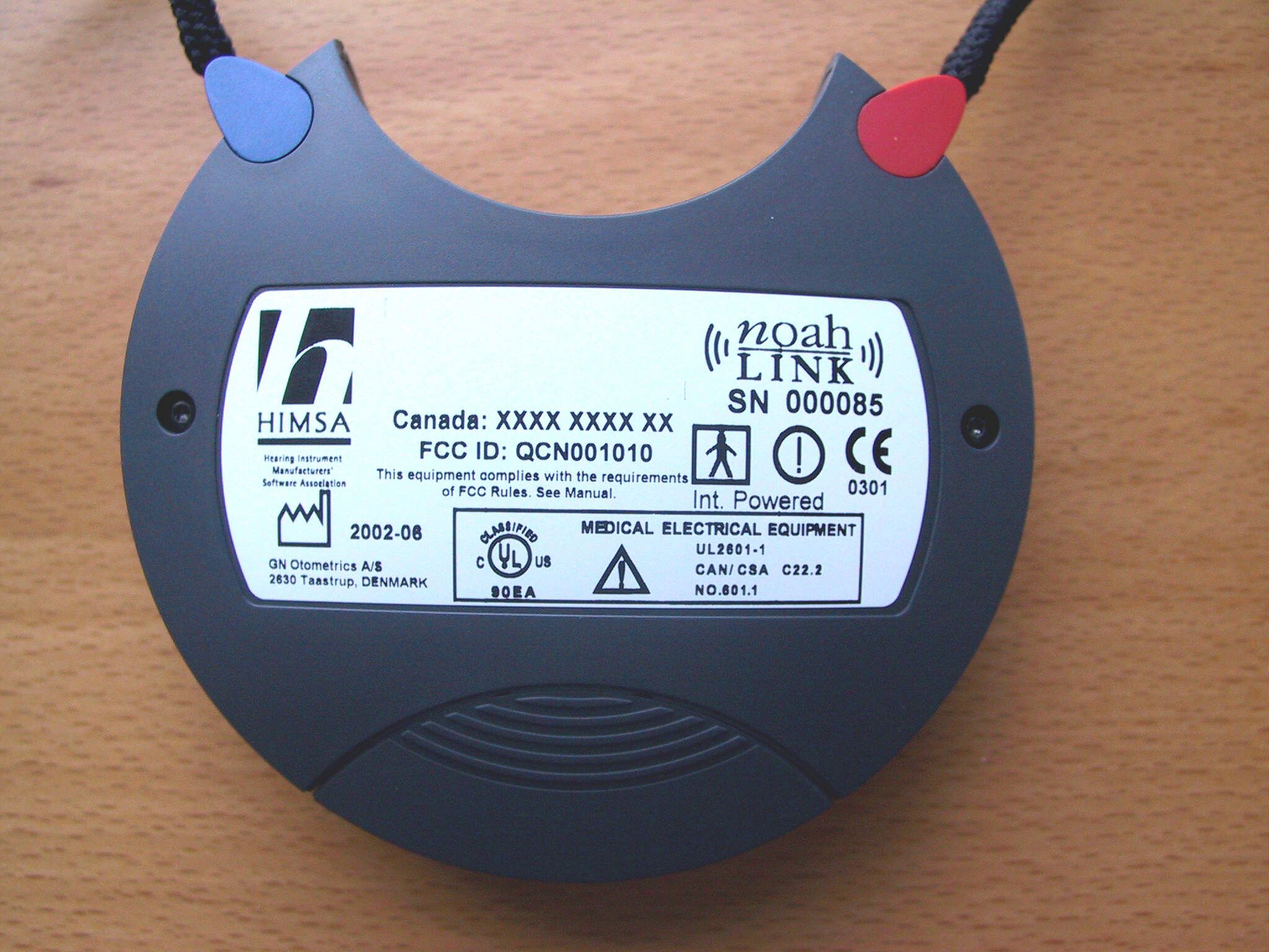
QCN001010NOAHlink Wireless Bluetooth communication device
GN Otometrics A/S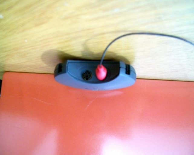
Click to zoom
Application Details
- Equipment Class
- DSS - Part 15 Spread Spectrum Transmitter
- Date of Grant
- Aug 28, 2002
- Application Purpose
- Original Equipment
- Date of Application
- Aug 28, 2002
- Equipment Note
- NOAHlink Wireless Bluetooth communication device
- Frequency Range
- 2402.00000000 - 2480.00000000
- Company
- GN Otometrics A/S
- Country
- Denmark
Documents & Files
Document Text
Text extracted from the exhibit documents filed with the FCC. Open a document above to read the original.
Users Manual
NOAHlink Users Manual Language Versions NOAHlink Users Manual................................................................1 NOAHlink Bedienungsanleitung.................................................37 NOAHlink brugermanual.............................................................71 NOAHlink Användarmanual.....................................................105 1 NOAHlink Users Manual 2 NOAHlink is manufactured for HIMSA by: GN Otometrics A/S Dybendalsvænget 2 DK-2630 Taastrup Denmark Trademarks NOAHlink is a trademark of HIMSA A/S. Windows is a registered trademark of Microsoft Corporation. Copyright This manual is copyrighted by HIMSA A/S with all rights reserved. Under copyright laws, this manual cannot be reproduced in any form without written permission of HIMSA A/S. © 2001 by HIMSA A/S. All rights reserved. Information in this document is subject to change without notice. 7-26-66400/05 2010-503000 (R 05) 3 Contents 1First Time Installation 5 2Introduction6 2.1ABOUT THIS MANUAL.....................................................................................6 3Safety Issues7 3.1MANUFACTURER RESPONSIBILITY...................................................................7 3.2SYMBOLS.......................................................................................................7 3.2.1NOAHlink Symbols...............................................................................7 3.2.2Charger Unit Symbols...........................................................................8 3.3WARNING NOTES...........................................................................................8 3.3.1NOAHlink Warning Notes....................................................................9 3.3.2Charger Unit Warning Notes.............................................................10 4Description11 4.1STANDARD ELEMENTS..................................................................................11 4.2OPTIONAL ACCESSORIES...............................................................................12 4.3OVERVIEW...................................................................................................12 5Maintenance13 5.1UNPACKING AND INSPECTION........................................................................13 5.2STORAGE AND SHIPMENT..............................................................................13 5.3CARE AND MAINTENANCE.............................................................................14 5.4SERVICE AND REPAIR....................................................................................14 6Installing NOAHlink15 6.1BATTERY USAGE..........................................................................................15 6.1.1Alkaline Battery...................................................................................16 6.1.2Rechargeable Battery..........................................................................16 6.2INSTALLATION.............................................................................................17 7Using and Charging NOAHlink18 7.1USING NOAHLINK.......................................................................................18 7.2DISCHARGING AND RECHARGING NOAHLINK................................................21 8Configuring NOAHlink22 8.1GENERAL APPLICATIONS...............................................................................24 8.1.1Connecting to NOAHlink....................................................................24 8.1.2Setting Power, Battery and Language Options.................................26 8.2ADVANCED APPLICATIONS............................................................................28 8.2.1Displaying Errors in NOAHlink and Bluetooth................................28 8.2.2Testing Data Transfer Rates...............................................................29 8.2.3Viewing and Setting the Log...............................................................30 NOAHlink Users Manual 4 ANOAHlink Troubleshooting32 BTechnical Specifications33 B.1NOAHLINK UNIT..........................................................................................33 B.1.1Battery..................................................................................................33 B.1.2Dimensions and Weight......................................................................33 B.1.3Patient Safety.......................................................................................33 B.2CHARGER UNIT.............................................................................................34 B.2.1Power Supply.......................................................................................34 B.2.2Dimensions and Weight......................................................................34 B.3POWER ADAPTOR..........................................................................................34 B.3.1Power Supply.......................................................................................34 B.4TRANSPORT AND STORAGE.............................................................................34 B.5OPERATING ENVIRONMENT............................................................................34 B.6STANDARD AND OPTIONAL ACCESSORIES........................................................34 NOAHlink Users Manual 5 1 First Time Installation The following steps describe how to prepare for NOAHlink™ installation and how to install your unit: 1. Before installing NOAHlink, you must install a Bluetooth device in your PC. Check whether this device is installed by right-clicking My Computer on your desktop, then selecting Properties from the pull-down menu. This opens the System Properties window. Open the Hardware tab. Click on Device Manager. Double-click on Ports to discover whether Bluetooth Communications Ports are listed. If these are listed, move to Step 3. 2. Before choosing and installing a Bluetooth device, refer to the NOAHlink page on HIMSA’s web site at www.…
Text truncated - open the document above for the full version.
Cover Letter(s)
American Telecommunications Certification Body Inc. 6731 Whittier Ave, McLean, VA 22101 June 29, 2002 RE: FCC ID: QCN001010 Attention: Morton Hoest I have a few comments on this Application. 1 There has been no request for confidentiality. Consequently, all application documents will be considered not confidential. If you wish to have the schematics, Block diagram and theory of operation held confidential you will have to submit a request for confidentiality under CFR47 0.457 and 0.459. 2 Internal photos are blurred and unreadable. Please provide Internal photos that are clear and readable. 3 The label and the physical area on the device are of sufficient size capability to contain the FCC ID label and the required 15.19 (two-condition) statement. Please provide an FCC ID label meeting the requirements of 2.925 and 15.19. 4 15.21 (Information to user) states, “The users manual or instruction manual for an intentional or unintentional radiator shall caution the user that changes or modifications not expressly approved by the party responsible for compliance could void the user's authority to operate the equipment.” The manual only states the manufacturer is not responsible for unauthorized modification. This is does not a warn to the user that any modification not approved by the manufacturer will void the user’s authority to use the device. Please provide a corrected manual with a statement in line with the intent of 15.21 5 15.247C states the 20dB requirement for radiated emissions, however it also states that in the restricted bands of 15,205 must meet the 15.209 limits. The peak cannot be higher than 74dBuV/m and the averaged readings above 1 GHz cannot be higher than 54dBuV/m. The restricted band of concern in the report are - 2483.5-2500MHz, 4.5-5.15GHz and 7.25- 7.75GHz. The peak readings given for a number of restricted band frequencies on page 33 of the report are more than 54dBuV at 3meters. While this may comply with the 20dB over the averaged reading for peak readings, there are no averaged measurements in the report to show compliance for these frequencies in the restricted band to the 54dB average limit. The device therefore fails. Please retest and/or provide a report that shows compliance to 15.247 and the requirements of restricted band limits in 15.205 and 15.209. 6 The maximum 20dB bandwidth for a frequency hopping Spread Spectrum device in the 2.4 GHz range is 1 MHz. The 1 MHz limit can be exceeded when at least 15 channels and not overlapping. In page mode and acquisition mode channel separation is greater than the 20dB bandwidth in that mode. Device is compliant. 7 The device appears to be a Part 15 digital device also. The manual must therefore contain the required statements of 15.105 and must declare the class of the device. Please provide a manual with this required statement or explain why you feel this is not a Part 15 digital device. 8 No schematics were provided for the transmitter. Please provide appropriate schematics of the transmitter. 9 Please provide a block diagram of the Bluetooth transmitter section. 10 No RF exposure (MPE) calculations have been provided. Please provide the required rf exposure calculations. l Page 2June 29, 2002 Dennis Ward mailto:[email protected] The items indicated above must be submitted before processing can continue on the above referenced application. Failure to provide the requested information may result in application termination. Correspondence should be considered part of the permanent submission and may be viewed from the Internet after a Grant of Equipment Authorization is issued. Please do not respond to this correspondence using the email reply button. In order for your response to be processed expeditiously, you must submit your documents through the AmericanTCB.com website. Also, please note that partial responses increase processing time and should not be submitted. Any questions about the content of this correspondence should be directed to the sender.
Cover Letter(s)
1. A request for confidentiality has now been uploaded and can be found in the Correspondence folder. Descriptions, diagrams and part lists should be kept confidential. 2. New and clearer photos have been uploaded. See file “Photos internal-mod” 3. It is correct that the label do not contain the full text of 15.19. This is due to the limited product and label size. The label space left is reserved for mandatory markings for selling the products on Asian markets. However the product label contains the following statement and reference to the user manual ”This equipment complies with the requirements of FCC rules. See Manual.” and on page 8 of the user manual the full text of §15.19 is to be found. I hope that this can be accepted, as using different labels for each marked could become very costly. 4. The user manual is changed according to your recommendations and is now in compliance with 15.21. See document ”NOAHlink Users Manual_US-mod” 5. Average measurements of emissions above 54dBuV/m in the 2483.5 – 2500MHz , 4.5 – 5.15GHz and 7.25 –7.75GHz bands is now included in the modified test report on page 33 (annex 17). See “GN-Otometrics NOAHlink-FCC-rapp (UPRR02008-02) –mod” 6. No change. 7. Statement from 15.105 is now included in the manual on page 9. See document ”NOAHlink Users Manual_US-mod” 8. Block diagram and user manual / operational description for the radio module are now uploaded ”ROK-Block diagram” and ”ROK-Operational description”. Schematics are not available however the module have been approved by the FCC and are listed under PNI8001001 (mentioned in test report under 3.1) 9. See under item 8. 10. A calculation according to 1.1310 is provided to show that the product does no pose any radiation hazard. See uploaded document ”RF exposure”
External Photos
External photos of GN Otometrichs A/S, NOAHlink Project No. UPRR020008-02 Back side of EUT Front side of EUT Top of EUT (connectors) Bottom of EUT (Battery)
ID Label/Location Info
n n n n n n Attn.: Date22 July 2002 Dear Sirs, I am writing this letter in order to explain to you, why it is very important for us that we do not write the full text of §15.19 on the product label of the NOAHlink product, but instead refer to this text in the manual. First of all the NOAHlink product has a limited product size and the label is already covering most of the back size of the product. It would be esthetical unacceptable and very costly for us to enlarge the label area. The upper center part of the label field, which apparently is empty now, is reserved for a name label (size 30 x 10 mm). The name label is a label where the user can write a device name so that it is easy for him/her to distinguish different units from each other. A sheet of Name Labels is part of the product accessories and this feature is part of the product specifications for our customer (HIMSA). The very limited label space, which is left, is reserved for mandatory markings for selling the products on Asian markets. I sincerely hope that you can accept that we only write the full text of §15.19 in the user manual. Yours Sincerely Morten Hoest GN Otometrics A/S
RF Exposure Info
Power density calculation according to CFR47 1.1310 OET Bulletin 65 including Supplement C 02. July 2002/MBAR • P S = Max.power density according to CFR47 1.1310 and OET Bulletin 65, Supplement C for General Population/Uncontrolled Exposure (in appropriate units, e.g. mW/cm 2 ) • P = power input to the antenna (in appropriate units, e.g., mW) • G = power gain of the antenna in the direction of interest relative to an isotropic radiator • G dB = power gain of the antenna in dB. • R = distance from point of power density to the center of radiation of the antenna (appropriate units, e.g., cm) G dB := 1.2 dBiP := 1mW 1mW = 0dBm = Class2 Solving for R, gives: =>R= (-0.324 or +0.324) cm From the above calculation (disregard the negative value) it can be seen that the minimum distance to the antenna in order to comply with the maximum power density as described in CFR47 1.1310 and OET 65, supplement C, is less than 0.4cm. The calculation is based on the far-field formula, whereby the prediction is more conservative and will over predict the power density in the near-field, making this a "worst- case" prediction. Due to the shape of the EUT cabinet the closest possible distance from the radiating antenna to the body of the user will at least 1cm.
Test Report
Telelaboratoriet Test Report UPRR020008-02Page 2 of 16 Title: Test on GN Otometrics A/S, NOAHlink, to FCC Part 15 C clause 15.209 and 15.247. Telelaboratoriet CONTENTSPAGE 1.TEST SPECIFICATION AND METHODS.............................................................4 2.LOCATION OF TEST SITE...................................................................................4 3.EUT DESCRIPTION..............................................................................................5 3.1.General........................................................................................................5 3.2.Technical specifications............................................................................5 4.TESTS AND TEST CONDITIONS.........................................................................5 4.1.EUT ports to be examined..........................................................................5 4.2.Operation of the EUT..................................................................................6 4.3.Limits and frequency ranges used............................................................6 5.MEASUREMENTS, EXAMINATIONS AND DERIVED RESULTS.......................6 5.1.§15.247 (a) (1) – Separation of channels...................................................7 5.2.§15.247 (a) (1) – Number of hopping channels.........................................8 5.3.§15.247 (a) (1) – 20 dB bandwidth..............................................................9 5.4.§15.247 (a) (1) – Occupancy of individual frequencies..........................10 5.5.§15.247 (b) (1) – Maximum peak output power.......................................11 5.6.§15.247 (c) – RF power, conducted measurement.................................12 5.7.§15.209 (a) – Radiated emission..............................................................13 5.8.§15.247 (a) (2) – 6 dB bandwidth, acquisition (inquiry / page)...............14 5.9.§15.247 (d) – Spectral power density, acquisition (inquiry / page).......15 6.LIST OF INSTRUMENTS....................................................................................16 Telelaboratoriet Test Report UPRR020008-02Page 3 of 16 Title: Test on GN Otometrics A/S, NOAHlink, to FCC Part 15 C clause 15.209 and 15.247. Telelaboratoriet Annexes: Normal mode 1: Separation of channels 2: Number of hopping channels 3 - 5: 20 dB bandwidth 6 - 7: Occupancy of individual frequencies 8 - 16: Radiated emission (Pre-scan) 17: Radiated emission (Final measurement) 18-19: Radiated emission at TX band edges Acquisition mode 20: Channels used in inquiry mode 21 – 23:Bandwidths, Inquiry mode 24: Channels used in Page mode 25 – 27:Bandwidths, Page mode 28:Spectral power density, inquiry mode 29:Spectral power density, page mode Telelaboratoriet Test Report UPRR020008-02Page 4 of 16 Title: Test on GN Otometrics A/S, NOAHlink, to FCC Part 15 C clause 15.209 and 15.247. Telelaboratoriet 1. Test Specification and Methods Purpose of Test:The tests are performed in order to demonstrate compliance with the FCC requirements for frequency hopping intentional transmitters operating in the freq. range 2400MHz to 2483,5MHz. Test Specifications: Limits: [1]CFR 47 Part 15 : 2001, Code of Federal Regulation 47 (Telecommunication), Part 15 (Radio Frequency Devices), Subpart C (Intentional Radiators) Clause 15.209 and 15.247 Methods and Procedures: The Test methods and procedures are defined in the following standard(s) (for undated references the latest edition applies): [2]ANSI C63.4 : 2000, American National Standard for Methods of Measurement of Radio-Noise Emissions form Low-Voltage Electrical and Electronic Equipment in the Range of 9 kHz to 40 GHz 2. Location of Test Site Test are performed at the test site of Tele Danmark A/S (Telelaboratoriet) at the address: Tele Danmark A/S (Telelaboratoriet) Telegade 2 DK-2630 Taastrup Denmark This site is listed at the FCC under the Registration Number 92797 since December 19, 2001. The FRN number for Telelaboratoriet is 0005-0898-67. Telelaboratoriet Test Report UPRR020008-02Page 5 of 16 Title: Test on GN Otometrics A/S, NOAHlink, to FCC Part 15 C clause 15.209 and 15.247. Telelaboratoriet 3. EUT Description 3.1. General The EUT is a medical device providing a wireless link to hearing aids to be used during their individual calibration. The EUT operates in the 2.4GHz band and the RF and protocols used are based on the Bluetooth technology. Product:Medical Bluetooth Device Manufacture:GN Otometrics A/S Type No:NOAHlink The RF interface is provided by a Ericsson Bluetooth module, ROK 101 007 / 21, previously approved by the FCC and is listed under FCC ID number PNI8001001. 3.2. Technical specifications Frequency:2400,0 – 2483,5 MHz Number of channels:79 (2402 – 2480) Type of modulation:GFSK, FHSS (TDD) Output power:0dBm / 1 mW Antenna type:Internal Antenna gain:1,2dBi (max) Power supply:1,5VDC (Alkaline battery) or 1.2VDC (rechargeable NiMH battery) Type of equipment:Bluetooth Transceiver class 2 Temperature range:5 – 45 deg. C. 4. Tests and test conditions 4.1. EUT ports to be examined Following port was examined during the tests: 1. Enclosure port Telelaboratoriet Test Report UPRR020008-02Page 6 of 16 Title: Test on GN Otometrics A/S, NOAHlink, to FCC Part 15 C clause 15.209 and 15.247. Telelaboratoriet 4.2. Operation of the EUT The EUT was during all tests operated at its maximum output power (0dBm) and powered by a 1,5V alkaline battery (except during extreme conditions where power were supplied by power supply). EUT was set-up by a by a lab-top PC with a Bluetooth interface to operate in TX test mode and based upon the parameters given after the test mode command, package size, hopping on/off, TX frequency could be selected. All tests are performed with the internal antenna replaced with a 50 ohm connector (conduced measurement) with the exception of the radiated emission test (radiated measurement) which is performed with the actual antenna in place. 4.3. Limits and fr…
Text truncated - open the document above for the full version.
Test Setup Photos
Test set-up photos of GN Otometrichs A/S, NOAHlink Project No. UPRR020008-02 Final measurement on OATS (1) Final measurement on OATS (2) Final measurement on OATS (3)
Contact Information
Applicant
Morten Hoest(Director)
Technical Contact
Non-Technical Contact
GN Otometrics A/SMorten Hoest
[email protected]+45 72 111 309
Test Firm
Telelaboratoriet-TDC Mobil A/SMartin Arndt
Technical Specifications
| # | Rule Parts | Frequency Range | Power Output |
|---|---|---|---|
| 1 | 15C | 2.40 GHz - 2.48 GHz | 1.16 mW |
Other Applications from GN Otometrics A/S
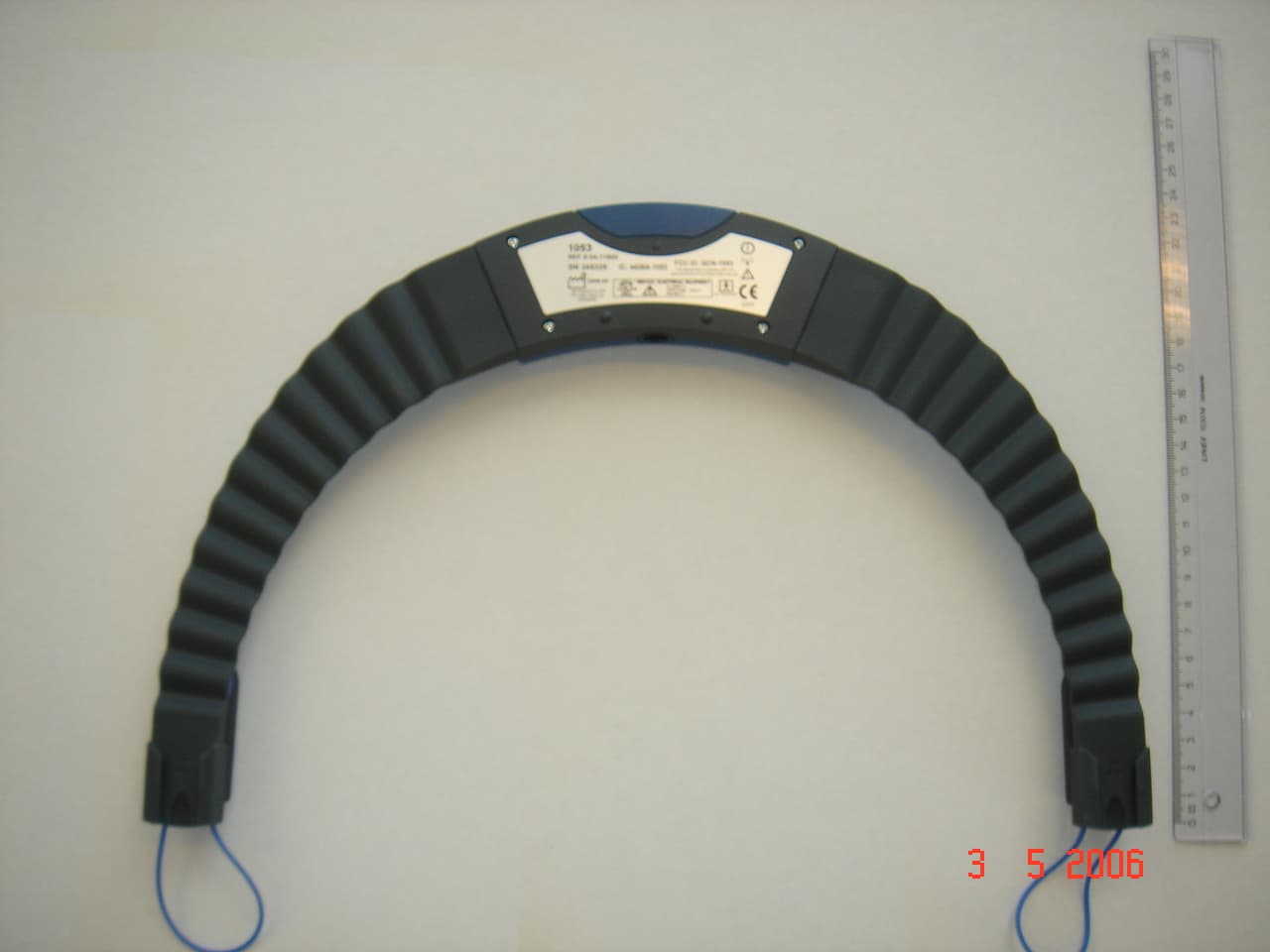
QCN-1053
Jul 27, 2006Medical Bluetooth Device
Equipment Class
DSS - Part 15 Spread Spectrum Transmitter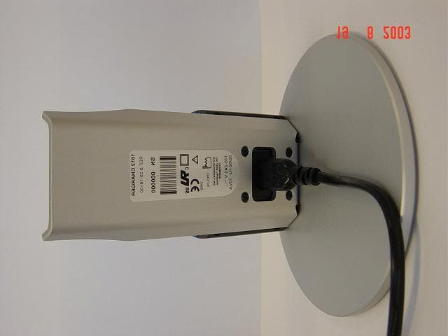
QCN-1012
Dec 17, 2003Medical Bluetooth Device
Equipment Class
DSS - Part 15 Spread Spectrum Transmitter