QDWWM168GC802.11g WLAN USB Module
AirVast Technology Inc.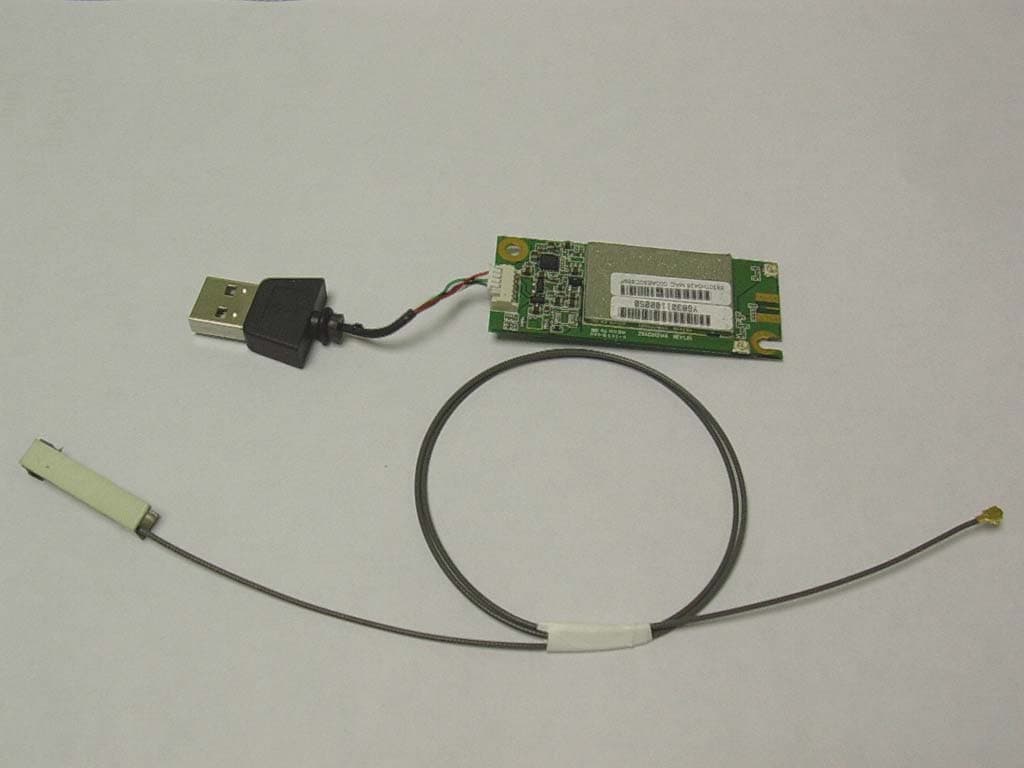
Click to zoom
Application Details
- Equipment Class
- DTS - Digital Transmission System
- Date of Grant
- Aug 09, 2004
- Application Purpose
- Original Equipment
- Date of Application
- Aug 09, 2004
- Equipment Note
- 802.11g WLAN USB Module
- Frequency Range
- 2412.00000000 - 2462.00000000
- Company
- AirVast Technology Inc.
- Country
- Taiwan
Documents & Files
Document Text
Text extracted from the exhibit documents filed with the FCC. Open a document above to read the original.
Users Manual
8 8 0 0 2 2 . . 1 1 1 1 g g W W L L A A N N U U S S B B M M o o d d u u l l e e WM-168gc OEM installation guide STATEMENT FOR MODUAL APPROVAL This product is sold to OEM integrators only. The manual for the OEM integrators must include some instructions to be followed by the end users in the user manual. For example: The OEM integrators must be instructed to ensure that the end user has no manual instructions to remove or install the device. The OEM integrators must be instructed about the end product labeling ("Contains FCC ID:QDWWM168GC ") This device is intended only for OEM integrators under the following conditions: 1) The antenna must be installed such that 20 cm is maintained between the antenna and users, and 2) The transmitter module may not be co-located with any other transmitter or antenna. As long as the 2 conditions above are met, further transmitter test will not be required. However, the OEM integrator is still responsible for testing their end product for any additional compliance requirements required with this module installed (for example, digital device emissions, PC peripheral requirements, etc.). IMPORTANT NOTE: In the event that these conditions cannot be met (for example certain laptop configurations or co-location with another transmitter), then the FCC authorization is no longer considered valid and the FCC ID can not be used on the final product. In these circumstances, the OEM integrator will be responsible for re-evaluating the end product (including the transmitter) and obtaining a separate FCC authorization. End Product Labeling This transmitter module is authorized only for use in device where the antenna may be installed such that 20 cm may be maintained between the antenna and users (for example, access points, routers, wireless ADSL modems, wireless media adapter, wireless media gateway, and similar equipment). The final end product must be labeled in a visible area with the following: " Contains FCC ID:QDWWM168GC ". Manual Information for OEM integrator Following RF exposure info shall be supplied in end-users manual depends on the application. For mobile configuration of RF Exposure Information: IMPORTANT NOTE: To comply with FCC RF exposure compliance requirements, this grant is applicable to only Mobile Configurations. The antennas used for this transmitter must be installed to provide a separation distance of at least 20 cm from all persons and must not be co-located or operating in conjunction with any other antenna or transmitter
Cover Letter(s)
Hi Mike, Please refer to the following for our replies. Thank you for your advice. Best regards, Ting -----Original Message----- From: Compliance Certification Services [mailto:[email protected]] Sent: Wednesday, August 04, 2004 4:20 PM To: [email protected] Subject: Airvast Technology Inc., FCC ID: QDWWM168GC, Assessment NO.: AN04T4094, Notice#1(revised) Question#1: Based on the modular request letter, this device is requested for the limited modular approval for installing in the following devices: access points, routers, wireless ADSL modems, wireless media adapter, wireless media gateway, and similar equipment. But from the EUT external photos, this device has an external USB connector and a PIFA antenna. Please explain how this device can be installed to the equipments mentioned on the modular request letter. Ans #1: The external USB connector is test kit for this module.(will not be included for sale) Question#2: FCC DOC logo is not applied to this application. Please remove it. Ans #2: Please refer to the attached for the revised label fomat. Question#3: Based on the modular request letter, this device is required to be installed by OEM manufacturer. However, in the submitted user manual, the manual is written in such way to allow the end user to install this product which does not agree with OEM installation instruction and marketing to OEM only. Please provide revised the user manual in such way that the user manual is addressed to OEM . Ans #3: The user's manual has been modify. Please refer to the attached. Question#4: Based on the test report and EUT external photos, a PIFA antenna is used for this device but the one indicated on the last page of user manual which indicates Chip antenna . Please explain. Ans #4: The user's manual has been modify. Please refer to the attached. Question#5: Page 3 of test report, the signature page, no signature included. Per ANSI C63.4 section 10.11.1, test report shall contain the signature of the representative of the organization performing the tests. Please provide. Ans #5: Page 3 of test report has been modify. Please refer to the attached. Question#6: Based on the EUT external photos, this device has two antenna connectors with a PIFA antenna. Please indicate which antenna connector was measured during test and how the other antenna connector will be used. Ans #6: This device will has one antenna connector with a PIFA antenna. Another antenna connector that will not using for Rx diversity by the software, so needless to SMT process for this component on the module. Best Regards, Mike Kuo The items indicated above must be submitted before processing can continue on the above referenced application. Failure to provide the requested information within 30 days of the original e-mail date may result in application dismissal and forfeiture of the filing fee. Also, please note that partial responses increase processing time and should not be submitted. Any questions about the content of this correspondence should be directed to the e-mail address listed below the name of the sender.
External Photos
Compliance Certification Services Inc. Report No: 40728201 Date of Issue: July 29, 2004 Page 1 of 3 EXTERNAL PHOTOGRPHS OF EUT
ID Label/Location Info
ModeL:WM-168gc FCC ID:QDWWM168GC 802.11g WLAN USB Module ModeL:WM-168gc FCC ID:QDWWM168GC 802.11g WLAN USB Module
Internal Photos
Compliance Certification Services Inc. Report No: 40728201 Date of Issue: July 29, 2004 Page 2 INTERNAL PHOTOGRPHS OF EUT Compliance Certification Services Inc. Report No: 40728201 Date of Issue: July 29, 2004 Page 3
Parts List/Tune Up Info
. V so ELECTRIC CO., LTD. Cabling Manufacturer TECHNICAL DATA ELECTRICAL PROPERTIES FREQUENCY RANGE 2.4 ~ 2.5 GHZ IMPEDENCE 50Ω VSWR ≦2 PROTOCOL SPEC. 802.11B POLARIZATION VERTICAL ELECTRICAL WAVE λ/4 DIPOLE CONNECTOR IPEX 或 同級品 WIRE ψ1.13 COAXIAL CABLE 或 同級品 MECHANICAL PROPERTIES ANTENNA COVER NONE COLOR NONE OPERATION TEMPERATURE -20 ~ +60 °C STORAGE TEMPERATURE -30 ~ +75 °C 2 天線垂直及水平場效圖 H-PLANE-2.4GHZ=-1.6dbi E-PLANE-2.4GHZ=+0.9dbi H+E H-PLANE-2.45GHZ=-1.7dbi E-PLANE-2.45GHZ=+1.0dbi H+E H-PLANE-2.5GHZ=-2.4dbi E-PLANE-2.5GHZ=+1.3dbi H+E 4 RETURN LOSS (迴損) 5 ψ1.13 COAXIAL CABLE線材特性資料 6 IPEX接頭特性資料 7 8
Test Report
Compliance Certification Services Inc. Report No: 40728201-RP FCC ID: QDWWM168GC Date of Issue: July 29, 2004 Note: This report shall not be reproduced except in full, without the written approval of Compliance Certification Services Inc. This document may be altered or revised by Compliance Certification Services Inc. personnel only, and shall be noted in the revision section of the document. Page 1 of 64 FCC 47 CFR PART 15 Subpart C TEST REPORT For AirVast Technology Inc. 802.11g WLAN USB Module Trade Name: AirVast Model: WM-168gc Prepared for AirVast Technology Inc. 4F, Ln. 21, Hsin Hua Rd., Kueishan Industrial Park, Taoyuan 330, Taiwan, R.O.C. Prepared by Compliance Certification Services Inc. No. 81-1, Lane 210, Bade Rd. 2, Luchu Hsiang, Taoyuan Hsien, (338) Taiwan, R.O.C. TEL: 886-3-324-0332 FAX: 886-3-324-5235 Compliance Certification Services Inc. Report No: 40728201-RP FCC ID: QDWWM168GC Date of Issue: July 29, 2004 Page 2 TABLE OF CONTENTS 1. TEST RESULT CERTIFICATION....................................................................................................3 2. EUT DESCRIPTION ...........................................................................................................................4 3. TEST METHODOLOGY ....................................................................................................................5 3.1 EUT CONFIGURATION........................................................................................................................5 3.2 EUT EXERCISE....................................................................................................................................5 3.3 GENERAL TEST PROCEDURES.............................................................................................................5 3.4 FCC PART 15.205 RESTRICTED BANDS OF OPERATIONS........................................................6 3.5 DESCRIPTION OF TEST MODES...........................................................................................................6 4. INSTRUMENT CALIBRATION........................................................................................................7 5. FACILITIES AND ACCREDITATIONS ..........................................................................................8 5.1 FACILITIES....................................................................................................................................... 8 5.2 EQUIPMENT........................................................................................................................................8 5.3 LABORATORY ACCREDITATIONS AND LISTING..................................................................................8 5.4 TABLE OF ACCREDITATIONS AND LISTINGS.......................................................................................9 6. SETUP OF EQUIPMENT UNDER TEST .......................................................................................10 6.1 SUPPORT EQUIPMENT......................................................................................................................10 6.2 SUPPORT EQUIPMENT ...............................................................................................................10 7. FCC PART 15.247 REQUIREMENTS.............................................................................................11 7.1 6 DB BANDWIDTH.............................................................................................................................11 7.2 PEAK POWER....................................................................................................................................16 7.3 BAND EDGES MEASUREMENT ................................................................................................21 7.4 PEAK POWER SPECTRAL DENSITY....................................................................................................30 7.5 RADIO FREQUENCY EXPOSURE........................................................................................................35 7.6 SPURIOUS EMISSIONS ................................................................................................................35 7.7 POWERLINE CONDUCTED EMISSIONS...............................................................................................60 APPENDIX 1 PHOTOGRPHS OF TEST SETUP .................................................................................63 Compliance Certification Services Inc. Report No: 40728201-RP FCC ID: QDWWM168GC Date of Issue: July 29, 2004 Page 4 2. EUT DESCRIPTION Product 802.11g WLAN USB Module Trade Name AirVast Model Number WM-168gc Model Discrepancy N/A Power Supply Powered form the host device Frequency Range IEEE 802.11b,g: 2412 ~ 2462 MHz Transmit Power IEEE 802.11b: 18.80 dBm IEEE 802.11g: 19.04 dBm Modulation Technique IEEE 802.11b: DSSS (CCK; DQPSK; DBPSK) IEEE 802.11g: OFDM Antenna Specification PIFA Antenna Gain: 1.3 dBi (max) Note: This submittal(s) (test report) is intended for FCC ID: QDWWM168GC filing to comply with Section 15.207, 15.209, 15.247. Compliance Certification Services Inc. Report No: 40728201-RP FCC ID: QDWWM168GC Date of Issue: July 29, 2004 Page 5 3. TEST METHODOLOGY The tests documented in this report were performed in accordance with ANSI C63.4 and FCC CFR 47 2.1046, 2.1047, 2.1049, 2.1051, 2.1053, 2.1055, 2.1057, and 15.207, 15.209,15.247. 3.1 EUT CONFIGURATION The EUT configuration for testing is installed on RF field strength measurement to meet the Commissions requirement and operating in a manner that intends to maximize its emission characteristics in a continuous normal application. 3.2 EUT EXERCISE The EUT was operated in the engineering mode to fix the TX frequency that was for the purpose of the measurements. According to its specifications, the EUT must comply with the requirements of the Section 15.207, 15.209,15.247 under the FCC Rules Part 15 Subpart C. 3.3 GENERAL TEST PROCEDURES C…
Text truncated - open the document above for the full version.
Test Setup Photos
Compliance Certification Services Inc. Report No: 40728201-RP FCC ID: QDWWM168GC Date of Issue: July 29, 2004 Page 63 APPENDIX 1 PHOTOGRPHS OF TEST SETUP Radiated Emission Set up Photos Compliance Certification Services Inc. Report No: 40728201-RP FCC ID: QDWWM168GC Date of Issue: July 29, 2004 Page 64 Conducted Emission Set Up Photos
Contact Information
Applicant
Guo-Rong Hwang(Vice President)
Test Firm
Compliance Certification Services Inc.Kurt Chen
Technical Specifications
| # | Rule Parts | Frequency Range | Power Output |
|---|---|---|---|
| 1 | 15C | 2.41 GHz - 2.46 GHz | 80.00 mW |
Other Applications from AirVast Technology Inc.
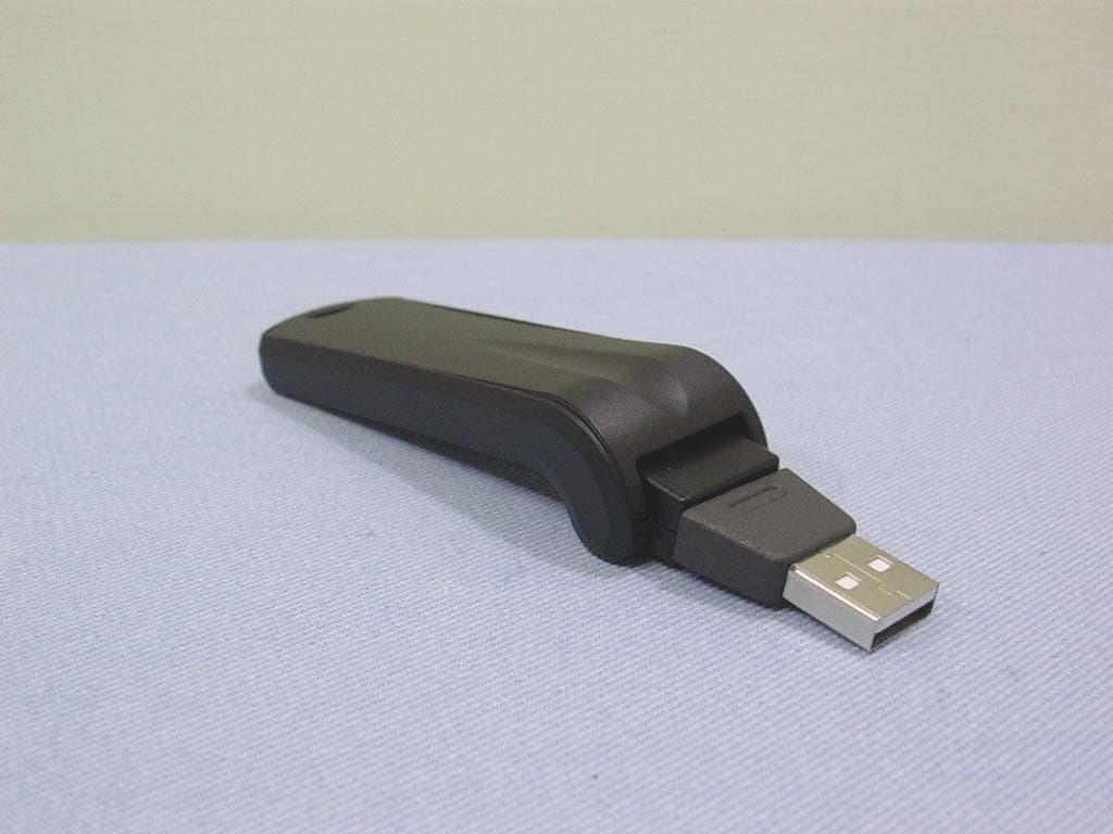
QDWWN250GC
Jun 14, 2004802.11 b/g WLAN USB Stick
Equipment Class
DTS - Digital Transmission System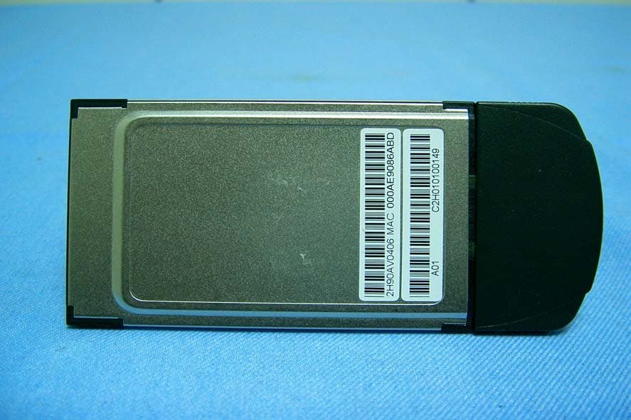
QDWWN113SH18
Mar 11, 2004802.11b WLAN PCMCIA Card W/Detachable Antenna
Equipment Class
DTS - Digital Transmission System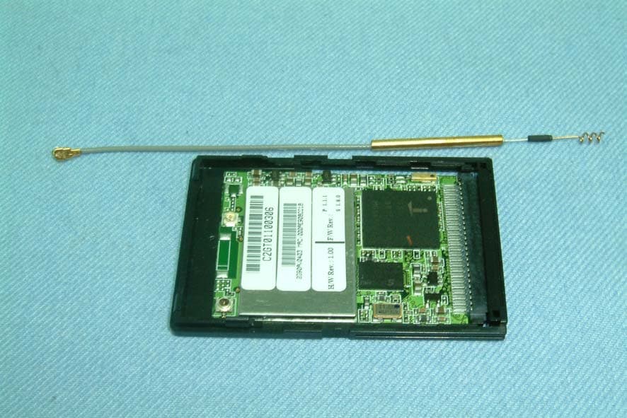
QDWWN500
Mar 08, 2004802.11b WLAN CF card
Equipment Class
DTS - Digital Transmission System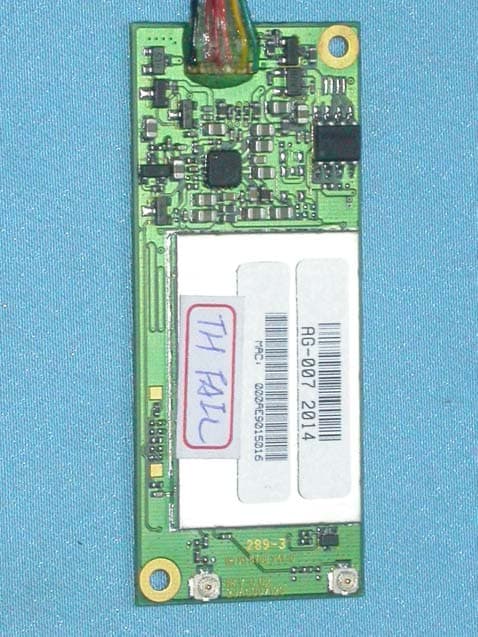
QDWWM168GI
Jan 12, 2004802.11g WLAN USB Module
Equipment Class
DTS - Digital Transmission System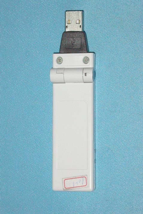
QDWWN250GI
Oct 22, 2003802.11g/b WLAN USB Stick
Equipment Class
DTS - Digital Transmission System