QE5HBM004Bluetooth Headset
HIT Incorporated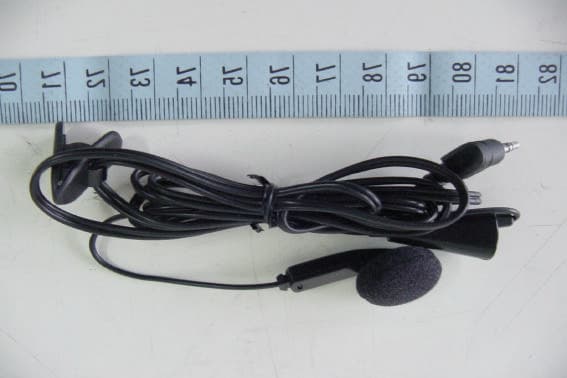
Click to zoom
Application Details
- Equipment Class
- DSS - Part 15 Spread Spectrum Transmitter
- Date of Grant
- Mar 05, 2003
- Application Purpose
- Original Equipment
- Date of Application
- Mar 05, 2003
- Equipment Note
- Bluetooth Headset
- Frequency Range
- 2402.00000000 - 2480.00000000
- Company
- HIT Incorporated
- Country
- Taiwan
Documents & Files
Document Text
Text extracted from the exhibit documents filed with the FCC. Open a document above to read the original.
Users Manual
HBM-004 User’s Manual The Wireless Headset is using standard Bluetooth technology. It is compatible with any Bluetooth enabled audio gateway devices. Its unique state-of-the-art design and user-friendly interface can bring you the most convenient way of life. Front 1. Power Key/Talking Button 2. Volume up Key 3. Volume down Key 4. Status Indicator StandbyGreen light flashing once in 4 seconds Pairing: Green & Red light alternately flashes once / second TalkingGreen light flashing 3 times / second Low Battery StandbyRed light flashing once in 4 seconds Low Battery talkingRed light flashing 3 times / second ChargingRed light on Charging completeRed light off 5. Earpiece receiver 6. Earpiece microphone 7. Earpiece audio jack Side 8. Re-set Key Headset’s safety installation, which can enable the headset to be back to the original status. 9. Headset clip 4 3 2 1 5 6 7 8 9 Charge When first use this Bluetooth headset, the build-in battery is not fully charged. It is highly recommended to fully charge the battery before first use. When charging the battery, please see the below diagram followed by the instruction. First, please plug in the transformer (13) into an AC wall plug, then connect the transformer output connector (12) with headset charger jack (11), the status indicator (4) will turn on and it will be red by now, meaning that the headset is being charged at the moment. The charger takes about 2 hours to be fully charged; when the red light of the status indicator (4) turns off, the charging process is completed. 11 10 12 13 10. Headset audio jack 11. Headset charging jack 12. Transformer output connector 13. Transformer Pairing Instruction When first use this Bluetooth headset, please go through the pairing process with a Bluetooth supported mobile phone. The pairing process only needs to go through once when first use. Headset 1. With the headset turned off (the headset status indicator light is switched off). 2. Press & hold the power key for over 10 seconds (you can hear beeper tones from earpiece receiver at the 5 th seconds), the green & red light will be flashing alternately once/second, meaning that the headset is already in pairing process. Mobile phone When pairing with Bluetooth supported mobile phone, different brands may have different pairing instructions, please read the user manual carefully before start. The following operation instructions are based on Nokia 8910 &Ericsson T68 Nokia 8910 Scroll to Menu- Bluetooth - On The screen will show “Bluetooth switched on” Choose “Search for audio accessories” When the screen shows”HBM-004”, press Select Enter passcode: press 0000, then press OK When the screen shows “connected to HBM-004” & the headset status indicator changes to green light flashing once in 4 seconds from the green & red light flashing alternately once/ second, meaning that the pairing process succeeds. Press “”key on mobile phone to enter “View paired devices” press Select Press ”HBM-004” Options, Press “”key to enter “Request conn. Authorization” press Select, Select No The screen will show “No author. Required” Press BackExit return to Main Screen Attention1. For power saving consideration, the headset will disconnect mobile phone after pairing completing 15 seconds without pressing mobile phone any keys. And mobile phone screen will show “Disconnected: HBM-004” at the same time. 2. If pairing process fails, please go through the process again. Finish the pairing process within 2 minutes if possible. Sony Ericsson T68 Scroll to Menu, Connect – Bluetooth – Discover When the screen shows HBM-004 press YES Add to pairedpress YES A headset is already paired with the phone. Replaced? Press YES PasskeyPress 0000and then press YES Pairing succeededName tag Press NO Add devicePress NO Operation mode can be set to On or Automatic However, if you wish to use the voice control function, you will need to set the Operation mode to On. AttentionIf pairing process fails, please go through the process again. Finish the pairing process within 2 minutes if possible. Turn the headset on Press and hold Power Key over 5 seconds, you can hear beeper tones from earpiece receiver also the headset status indicator light flashes green. If the battery is low, the light flashes red. Turn the headset off Press and hold Power Key over 5 seconds, you can hear beeper tones from earpiece receiver also the headset status indicator light is switched off. Answering When the headset is on, the green light will be flashing once in 4 seconds, meaning that the headset is on standby mode. When call comes in, please press the talking button to answer the call. To hang up, press the same button or operate from the phone. Outgoing call Nokia 8910 Let headset establish connection with mobile phone at first: press headset talking button one time, you will hear beeper tone from headset & mobile phone screen will show ”Connected to HBM-004” Then directly dial numbers from mobile phone, the call will transfer automatically from the phone to headset. Attention: Please complete to dial numbers within 15 seconds after establishing connection between headset & mobile phone. Otherwise mobile phone will disconnect headset (mobile phone screen will show “Disconnected to: HBM-004”), you must need to connect headset & mobile phone again. Sony Ericsson T68 When headset is on standby mode, directly dial numbers from the mobile phone, the call will transfer automatically from the phone to headset. Voice Control If your mobile phone supports voice control function, then press headset talking button 2 times, you can hear beeper tones from your headset, you can operate the voice control function as usual way. Switching When call comes in, if you answered from your mobile phone, you can switch the call to the headset during conversation. Press the talking button, and then the call will be transferred. Volume During conversation, you can adjust the volume by pressing the volume up/down key. FCC Statement 1.THIS DEVICE COM…
Text truncated - open the document above for the full version.
External Photos
ETC Report No. : ET91R-12-110 Sheet 1 of 6 Sheets FCC ID. : QE5HBM004 Rev. No 2.1 CONSTRUCTED PHOTOS of EUT 1. Front View of EUT 2. Front View of EUT ETC Report No. : ET91R-12-110 Sheet 2 of 6 Sheets FCC ID. : QE5HBM004 Rev. No 2.1 CONSTRUCTED PHOTOS of EUT 3. Side View of EUT 4. Side View of EUT ETC Report No. : ET91R-12-110 Sheet 5 of 6 Sheets FCC ID. : QE5HBM004 Rev. No 2.1 CONSTRUCTED PHOTOS of EUT 9. Front View of Adaptor 10. Rear View of Adaptor ETC Report No. : ET91R-12-110 Sheet 6 of 6 Sheets FCC ID. : QE5HBM004 Rev. No 2.1 CONSTRUCTED PHOTOS of EUT 11. Front View of Line
Internal Photos
ETC Report No. : ET91R-12-110 Sheet 3 of 6 Sheets FCC ID. : QE5HBM004 Rev. No 2.1 CONSTRUCTED PHOTOS of EUT 5. Internal View of EUT 6. Component View of PCB ETC Report No. : ET91R-12-110 Sheet 4 of 6 Sheets FCC ID. : QE5HBM004 Rev. No 2.1 CONSTRUCTED PHOTOS of EUT 7. Component View of PCB 8. Solder View of PCB
Operational Description
The Wireless Headset is using standard Bluetooth technology. It is compatable with any Bluetooth enable audio gateway device. It’s unique stale of the art design and user friendly interface can bring the most convenient way of life.
Test Report
Rev. No 2.1 FCC Part 15 EMI TEST REPORT of E.U.T. : Bluetooth Headset MODEL : HBM-004 FCC ID. : QE5HBM004 for APPLICANT : HIT Incorporated ADDRESS : 4F, 8, Lane 235, Pao-Chiao Road, Shin Tien City, Taipei, Taiwan, R.O.C. Test Performed by ELECTRONICS TESTING CENTER, TAIWAN NO. 34, LIN 5, DING FU TSUN, LINKOU HSIANG, TAIPEI HSIEN, TAIWAN, R.O.C. Tel:(02)26023052 Fax:(02)26010910 http://www.etc.org.tw ; e-mail:[email protected] Report Number : ET91R-12-110-01 ETC Report No. : ET91R-12-110-01 FCC ID. : QE5HBM004 Rev. No 2.1 TEST REPORT CERTIFICATION Applicant : HIT Incorporated 4F, 8, Lane 235, Pao-Chiao Road, Shin Tien City, Taipei, Taiwan, R.O.C. Manufacturer : HIT Incorporated 4F, 8, Lane 235, Pao-Chiao Road, Shin Tien City, Taipei, Taiwan, R.O.C. Description of EUT : a) Type of EUT : Bluetooth Headset b) Trade Name : HIT Incorporated c) Model No. : HBM-004 d) Power Supply : Input: 230Vac, 50Hz, 55mA; Output: 4.5Vdc, 300mA Regulation Applied : FCC Rules and Regulations Part 15 Subpart B & C (2002) I HEREBY CERTIFY THAT: The data shown in this report were made in accordance with the procedures given in ANSI C63.4, and the energy emitted by the device was founded to be within the limits applicable. I assume full responsibility for accuracy and completeness of these data. Note: 1. The result of the testing report relates only to the item tested. 2. The testing report shall not be reproduced expect in full, without the written approval of ETC. Issued Date : Jan. 21, 2003 Test Engineer : ( Keven Lee ) Approve & Authorized Signer : Will Yauo, Manager EMC Dept. II of ELECTRONICS TESTING CENTER, TAIWAN ETC Report No. : ET91R-12-110-01 FCC ID. : QE5HBM004 Rev. No 2.1 Table of Contents Page 1 GENERAL INFORMATION.......................................................................................................1 1.1 Product Description........................................................................................................................1 1.2 Characteristics of Device................................................................................................................1 1.3 Test Methodology..........................................................................................................................1 1.4 Test Facility....................................................................................................................................1 1.5 Modist List.....................................................................................................................................1 2 PROVISIONS APPLICABLE.......................................................................................................2 2.1 Definition........................................................................................................................................2 2.2 Requirement for Compliance...........................................................................................................3 2.3 Restricted Bands of Operation........................................................................................................5 2.4 Labeling Requirement.....................................................................................................................5 2.5 User Information............................................................................................................................6 3. SYSTEM TEST CONFIGURATION...........................................................................................7 3.1 Justification.....................................................................................................................................7 3.2 Devices for Tested System.............................................................................................................7 4 RADIATED EMISSION MEASUREMENT..............................................................................8 4.1 Applicable Standard.......................................................................................................................8 4.2 Measurement Procedure.................................................................................................................8 4.3 Measuring Instrument...................................................................................................................10 4.4 Radiated Emission Data................................................................................................................11 4.4.1 Fundatmental and Harmonics....................................................................................................11 4.4.2 Other Emissions.......................................................................................................................14 4.5 Field Strength Calculation.............................................................................................................15 4.6 Photos of Radiation Measuring Setup............................................................................................16 5 CONDUCTED EMISSION MEASUREMENT........................................................................17 5.1 Standard Applicable.....................................................................................................................17 5.2 Measurement Procedure...............................................................................................................17 5.3 Conducted Emission Data.............................................................................................................18 5.4 Result Data Calculation.................................................................................................................19 5.5 Conducted Measurement Equipment.............................................................................................19 5.6 Photos of Conduction Measuring Setup........................................................................................20 6 ANT…
Text truncated - open the document above for the full version.
Test Setup Photos
ETC Report No. : ET91R-12-110-01 Sheet 16 of 60 Sheets FCC ID. : QE5HBM004 Rev. No 2.1 4.6 Photos of Radiation Measuring Setup ETC Report No. : ET91R-12-110-01 Sheet 20 of 60 Sheets FCC ID. : QE5HBM004 Rev. No 2.1 5.6 Photos of Conduction Measuring Setup
Contact Information
Applicant
Alex Yang(Project Manager)
Test Firm
Electronics Testing Center, TaiwanWinpo Tsai
Technical Specifications
| # | Rule Parts | Frequency Range | Power Output |
|---|---|---|---|
| 1 | 15C | 2.40 GHz - 2.48 GHz | 1.00 mW |
Other Applications from HIT Incorporated
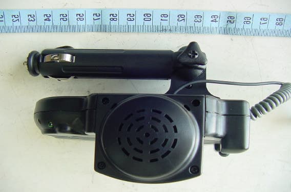
QE5HBK001
Jul 21, 2003Bluetooth Car Kit
Equipment Class
DSS - Part 15 Spread Spectrum Transmitter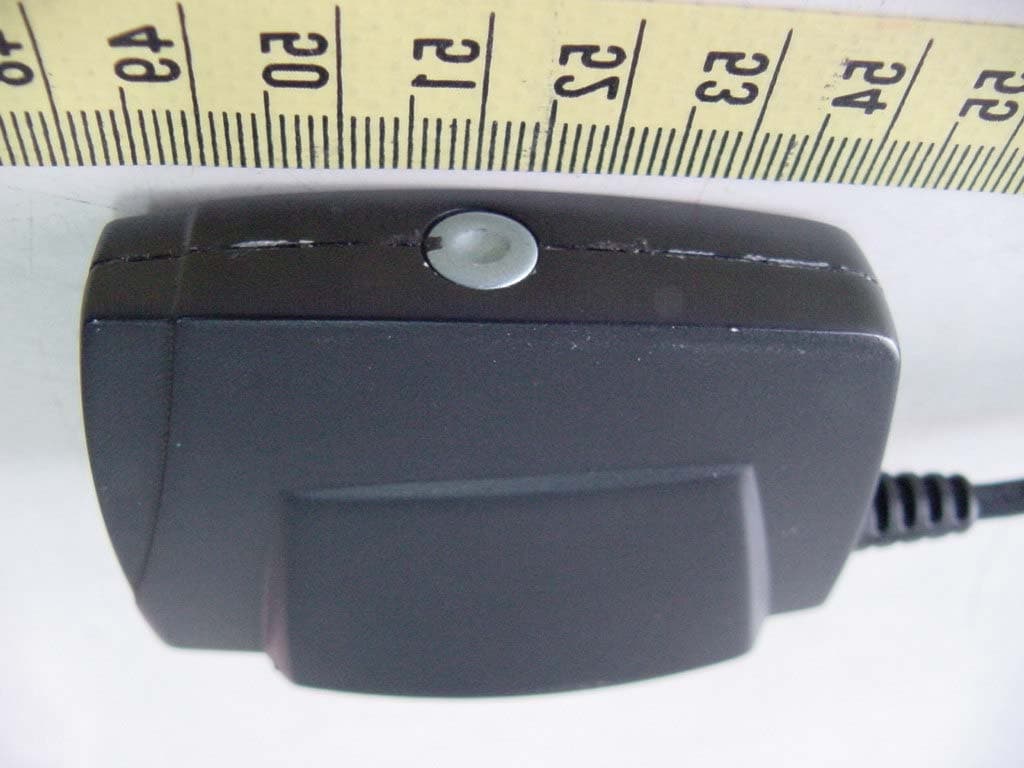
QE5HITBTUDHBU001
Sep 03, 2002Bluetooth USB Dongle
Equipment Class
DSS - Part 15 Spread Spectrum Transmitter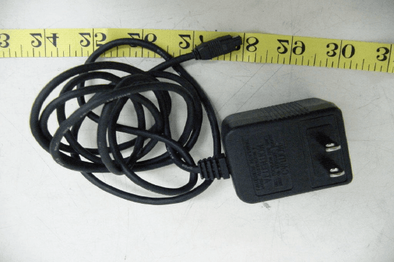
QE5HITBTPAHBA001
Jul 25, 2002Bluetooth Phone Adapter
Equipment Class
DXT - Part 15 Low Power Transceiver, Rx Verified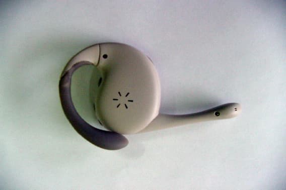
QE5HITBTHSHBM001
Jul 14, 2002Bluetooth Handset
Equipment Class
DXT - Part 15 Low Power Transceiver, Rx Verified