QE8403XXRemote Control Helicopter/Airplane Transmitter
Interactive Toy Concepts Limited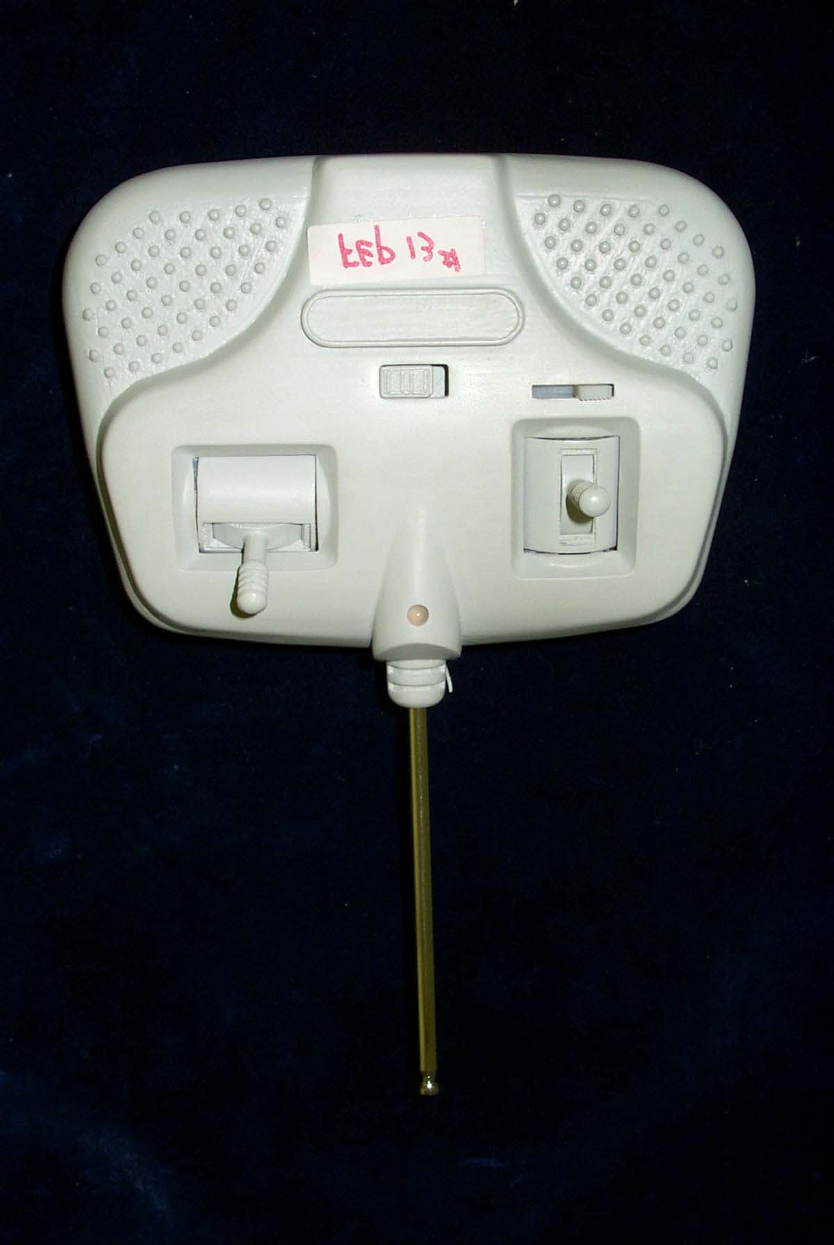
Click to zoom
Application Details
- Equipment Class
- DXX - Part 15 Low Power Communication Device Transmitter
- Date of Grant
- Jul 28, 2004
- Application Purpose
- Original Equipment
- Date of Application
- Jul 28, 2004
- Equipment Note
- Remote Control Helicopter/Airplane Transmitter
- Frequency Range
- 27.19500000 - 27.19500000
- Country
- Hong Kong
Documents & Files
Document Text
Text extracted from the exhibit documents filed with the FCC. Open a document above to read the original.
Users Manual
Model No. 403XX Operation Instruction Preparation 1. Battery used on Transmitter is 6 pcs of Alkaline ‘AA’ batteries. Open the battery cover on the Transmitter, insert 6 pcs ‘AA’ Alkaline batteries inside the battery compartment and cover the battery door. 2. Screw in the antenna on the Transmitter 3. The battery on the helicopter is rechargeable battery, which is charge by a charging connector coming out from the Transmitter. Charging the helicopter battery Connect the charge connector on the Transmitter to the charge connector at the bottom of the helicopter. 2. Slide the switch on the Transmitter to the upper position and the light on the transmitter will turn red while charging battery. The charging time requires about 20 minutes but the charger circuit inside the Transmitter can prevent it from overcharging. Flying the Helicopter 1. Please find an indoor place which has as few obstacle as possible 2. Please try to close all windows so that there is no wind or moving air 3. Switch on the micro switch at the bottom p1 the helicopter (slide the switch to the back) 4. Place the helicopter carefully on the ground 5. Extend the antenna on the Transmitter to full length 6. Slide the switch on the Transmitter to the upper position, the light will turn green. 7. The left stick control the helicopter move up and down, firstly reset the left stick to the lowest position. Then 2radually move the stick up, you will see both rotor start to accelerate and up to a certain speed, the helicopter will start to go up. Then you can continue to move the stick up or down carefully to keep the helicopter at certain height. Try to avoid moving the stick too quickly. 8. The right stick control the helicopter move forward/backward and also turn left/right. The control is as follow: - If the right stick is pushed up from middle to the top, the helicopter will start to go forward. - If the right stick is pushed down from middle to the bottom, the helicopter will start to go backward. - If the right stick is pushed to the right side, the helicopter will start to turn right. - If the right stick is pushed to the left side, the helicopter will start to turn left. 9. If you feel you can no longer keep the height of the helicopter, that means the battery on the helicopter is running out and you need to re-charge the battery again. 10. After landing, please switch off the helicopter (slide the micro switch at the bottom of helicopter to the front).
Cover Letter(s)
-----Original Message----- From: Weili Sent: Thursday, July 22, 2004 3:39 PM To: [email protected] Subject: Re: Interactive Toy Concepts(HK) Ltd., FCC ID: QE8403XX, Assessment NO.: AN0... Dear Mike, We re-do the test with average / Quasi-peak reading. Attached is the revised report. Operational description will be sent to you soon. Regards, Wei -----Original Message----- From: Weili Sent: Thursday, July 29, 2004 7:19 AM To: [email protected] Subject: Re: Interactive Toy Concepts(HK) Ltd., FCC ID: QE8403XX, Assessm ent NO.: AN... Hi, Mike. Attached is the operational description for QE8403XX. All required infor should be completed. Regards, Wei
External Photos
FCC ID: QE8403XX ——————————————————————————————————————————————— Advanced Compliance Lab, 6 Randolph Way, Hillsborough, NJ 08844 Tel: (908) 927-9288 Fax: (908) 927-0728 17 Front View FCC ID: QE8403XX ——————————————————————————————————————————————— Advanced Compliance Lab, 6 Randolph Way, Hillsborough, NJ 08844 Tel: (908) 927-9288 Fax: (908) 927-0728 18 Rear View
ID Label/Location Info
FCC ID: QE8403XX ——————————————————————————————————————————————— Advanced Compliance Lab, 6 Randolph Way, Hillsborough, NJ 08844 Tel: (908) 927-9288 Fax: (908) 927-0728 8 2. PRODUCT LABELING Figure 2.1 FCC ID Label Figure 2.2 Location of Label on the Side of EUT FCC ID: QE8 403XX This device complies with part 15 of the FCC Rules. Operating is subject to the following two conditions: (1) This device may not cause harmful interference, and (2) this device must accept any interference received, including interference that may cause undesired operation. Figure 2.1 FCC ID Label Figure 2.2 Location of the Label FCC Label
Internal Photos
FCC ID: QE8403XX ——————————————————————————————————————————————— Advanced Compliance Lab, 6 Randolph Way, Hillsborough, NJ 08844 Tel: (908) 927-9288 Fax: (908) 927-0728 19 Open View FCC ID: QE8403XX ——————————————————————————————————————————————— Advanced Compliance Lab, 6 Randolph Way, Hillsborough, NJ 08844 Tel: (908) 927-9288 Fax: (908) 927-0728 20 Component Side FCC ID: QE8403XX ——————————————————————————————————————————————— Advanced Compliance Lab, 6 Randolph Way, Hillsborough, NJ 08844 Tel: (908) 927-9288 Fax: (908) 927-0728 21 Foil Side
Operational Description
Applicant: Interactive Toy Concepts (HK) Ltd. FCC ID: QE8403XX Operational Circuit Description Item 1: Transmitter (R/C) The circuit consists of transmit circuit and charging circuit; The transmit circuit is powered by 9v (6F22) battery. Subordinate Signal circuit and IC1 (MCU are powered by Q4 (VCC at approx. 4.4v). It is a typical series regulated power supply. IC1(MCU) applies 3-channel specialized program. When transmit circuit is powered up, LED glows in green color. When VR1 is in the 0 position, transmit signal is close to 0. When VR1 is adjusted, IC1 (MCU) P1.0 (or P1.1) will transmit pulse codes proportionally. If VR2 is adjusted, tail motor speed will change in two different directions. If VR3 is adjusted, the speed difference between two main channels will change. When IC1 (MCU) detects that the voltage of 6F22 battery is under 7v, LED will glow in green color. Pulse codes pass D1 (a variable capacity 2105). The codes then are modulated to 27.195MHz in the signal oscillation circuit that consists mainly of Q3 and are transmitted out to the air. L1,T1 and C1,C2,C3 are for antenna matching and harmonic restrain. IC2 and its simple outskirt circuit are for charging management of battery on Rx. It is a SOC. Charging output is 4.715v-4.225v. Charging current is 390-526mA. Item 2: Receiver: Receiver consists of ANT1 (antenna), Q1 (RF amplification), IC1/3661 (modulator-demodulator), Q2 (signal processor and phase reversing unit), IC5 (MCU) and IC4, IC6 (motor driving circuit). ANT1 receives FM signal for 27.195MHz. The signal is amplified through Q1 and de-modulated by IC1 (3361). After passed Q2, the pulse codes are output to IC5 P0.0. IC5 will de-code for 3 channels duty-variable pulse signal to control IC4 (9926) to drive the main motors or control IC6 to drive the tail motor. IC4 and IC5 are powered by chargeable 3.7v 250mAh Lithium Polymer battery. Subordinate signal circuit and MCU are powered by LDO regulator-ML62252.
Schematics
FCC ID: QE8403XX ——————————————————————————————————————————————— Advanced Compliance Lab, 6 Randolph Way, Hillsborough, NJ 08844 Tel: (908) 927-9288 Fax: (908) 927-0728 12 4. SYSTEM SCHEMATICS Figure 4.1 System Schematics
Test Report
ELECTROMAGNETIC EMISSION COMPLIANCE REPORT of RADIO CONTROL HELICOPTER/AIRPLANE TRANSMITTER MODEL: 403XX FCC ID: QE8403XX July 12, 2004 This report concerns (check one): Original grant x Class II change Equipment type: Low Power Intentional Radiator Deferred grant requested per 47 CF 0.457(d)(1)(ii)? yes no x If yes, defer until: (date) Company agrees to notify the Commission by (date) of the intended date of announcement of the product so that the grant can be issued on that date. Transition Rules Request per 15.37? yes no x If no, assumed Part 15, Subpart B for unintentional radiators - the new 47 CFR [10-1-90 Edition] provision. Report prepared for: Interactive Toy Concepts (HK) Ltd. Report prepared by: Advanced Compliance Lab Report number: 0048-040614-01 The test result in this report IS supported and covered by the NVLAP accreditation 6 Randolph Way Hillsborough, NJ 08844 Tel: (908) 927 9288 Fax: (908) 927 0728 Advanced Compliance Laboratory FCC ID: QE8403XX ——————————————————————————————————————————————— Advanced Compliance Lab, 6 Randolph Way, Hillsborough, NJ 08844 Tel: (908) 927-9288 Fax: (908) 927-0728 2 Table of Contents Report Cover Page .........................................................................................................1 Table of Contents ...........................................................................................................2 Figures.............................................................................................................................3 1. GENERAL INFORMATION ...................................................................................4 1.1 Verification of Compliance .........................................................................4 1.2 Equipment Modifications............................................................................5 1.3 Product Information....................................................................................6 1.4 Test Methodology.........................................................................................6 1.5 Test Facility ..................................................................................................6 1.6 Test Equipment ............................................................................................6 1.7 Statement of the Document Use..................................................................7 2. PRODUCT LABELING............................................................................................8 3. SYSTEM TEST CONFIGURATION ......................................................................9 3.1 Justification ..................................................................................................9 3.2 Special Accessories.......................................................................................9 3.3 Configuration of Tested System .................................................................9 4. SYSTEM SCHEMATICS .........................................................................................12 5. RADIATED EMISSION DATA ...............................................................................13 5.1 Field Strength Calculation ..........................................................................13 5.2 Test Methods and Conditions .....................................................................13 5.3 Test Data .......................................................................................................13 6. PHOTOS OF TESTED EUT ....................................................................................15 FCC ID: QE8403XX ——————————————————————————————————————————————— Advanced Compliance Lab, 6 Randolph Way, Hillsborough, NJ 08844 Tel: (908) 927-9288 Fax: (908) 927-0728 3 Figures Figure 2.1 FCC ID Label...............................................................................................8 Figure 2.2 Location of Label on Back of the EUT ......................................................8 Figure 3.1 Radiated Test Setup, Position 1..................................................................10 Figure 3.2 Radiated Test Setup, Position 2..................................................................10 Figure 3.3 Radiated Test Setup, Position 3..................................................................11 Figure 4.1 EUT Schematics ...........................................................................................12 Figure 5.1 Bandwidth Plot ............................................................................................15 Figure 6.1 Front View....................................................................................................17 Figure 6.2 Rear View .....................................................................................................18 Figure 6.2 Inside View, Cover Opened ........................................................................19 Figure 6.3 Component Side ...........................................................................................20 Figure 6.4 Foil Side ........................................................................................................21 FCC ID: QE8403XX ——————————————————————————————————————————————— Advanced Compliance Lab, 6 Randolph Way, Hillsborough, NJ 08844 Tel: (908) 927-9288 Fax: (908) 927-0728 4 1. GENERAL INFORMATION 1.1 Verification of Compliance EUT: RADIO CONTROL HELICOPTER/AIRPLANE TRANSMITTER Model: 403XX Applicant: Interactive Toy Concepts (HK) Ltd. Unit 508, Tower B, New Mandarin Plaza, TST East Kowloon, Hong Kong Test Type: FCC Part 15C CERTIFICATION Result: PASS Tested by: ADVANCED COMPLIANCE LABORATORY Test Date: July 1, 2004 Report Number: 0048-040614-01 The above equipment was tested by Compliance Laboratory, Advanced Technologies, Inc. for compliance with the requirement set forth in the FCC rules and regulations Part 15 subpart C. This said equipment in the configuration described in the report…
Text truncated - open the document above for the full version.
Test Setup Photos
FCC ID: QE8403XX ——————————————————————————————————————————————— Advanced Compliance Lab, 6 Randolph Way, Hillsborough, NJ 08844 Tel: (908) 927-9288 Fax: (908) 927-0728 10 Figure 3.1 Radiated Test Setup, position 1-X Figure 3.2 Radiated Test Setup, position 2-Y FCC ID: QE8403XX ——————————————————————————————————————————————— Advanced Compliance Lab, 6 Randolph Way, Hillsborough, NJ 08844 Tel: (908) 927-9288 Fax: (908) 927-0728 11 Figure 3.3 Radiated Test Setup, position 3-Z
Contact Information
Applicant
Virginia Yeung(General Manager)
Test Firm
Advanced Compliance LaboratoryWei Li
Technical Specifications
| # | Rule Parts | Frequency Range | Power Output |
|---|---|---|---|
| 1 | 15C | 27.195 MHz - 27.195 MHz | - |
Other Applications from Interactive Toy Concepts Limited
QE822029TX
Aug 05, 20132.4G R/C Vehicle
Equipment Class
DXX - Part 15 Low Power Communication Device Transmitter
QE844077
Apr 15, 2012Wi-Spi Helicopter
Equipment Class
DTS - Digital Transmission System
QE844072TX27
Mar 17, 2011RC CAR
Equipment Class
DXX - Part 15 Low Power Communication Device Transmitter
QE844070TX49
Jan 13, 2011RC PLANE
Equipment Class
DXX - Part 15 Low Power Communication Device Transmitter
QE844070TX27
Jan 13, 2011RC PLANE
Equipment Class
DXX - Part 15 Low Power Communication Device Transmitter