QE8423XXTX27SNOWMOBILE
Interactive Toy Concepts Limited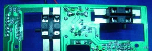
Click to zoom
Application Details
- Equipment Class
- DXX - Part 15 Low Power Communication Device Transmitter
- Date of Grant
- Aug 27, 2006
- Application Purpose
- Original Equipment
- Date of Application
- Aug 27, 2006
- Equipment Note
- SNOWMOBILE
- Frequency Range
- 27.14500000 - 27.14500000
- Country
- Hong Kong
Documents & Files
Document Text
Text extracted from the exhibit documents filed with the FCC. Open a document above to read the original.
Users Manual
INS-41011USEU-60322 Congratulations on the purchase of your Radio controlled snowmobile. Your new snowmobile is modeled after the real life and is specifically designed to be used outdoors on flat, packed snow. However to make your model more versatile, we have included a second set of (indoor) skis with built-in wheels to allow you to use your sled indoors on low-pile carpet. . The design of the radio controlled Snowmobile closely follows its full-size counterpart in terms of styling and functionality featuring true front and rear suspension systems, a high speed drive track, powerful electric motors and even a scale rider figure! Use under adult supervision! Copyright © 2006 INTERACTIVE TOY CONCEPTS LTD. - Printed in China Radio Controlled Snowmobile • Radio-Controlled Model • Outdoor / Indoor Use • Quiet & Clean Electric Power. • Requires a 9V Battery for the Transmitter • Requires a 9.6 V rechargeable NiCd or NiMH battery for snowmobile (may be included in this package). CCAAUUTTIIOONN:: EELLEECCTTRRIICCAALLLLYY OOPPEERRAATTEEDD PPRROODDUUCCTT:: AC CHARGER USED BY ADULT ONLY. NOT RECOMMENDED FOR CHILDREN UNDER 8 YEARS OF AGE. AS WITH ALL ELECTRIC PRODUCTS, PRECAUTIONS SHOULD BE OBSERVED DURING HANDLING AND USE TO PREVENT ELECTRIC SHOCK. INPUT: AC120V 60HZ 13W OUTPUT: DC12V 300mA UL LISTED CHARGER The Snowmobile is quite rugged but, as with any sophisticated device, you must learn how to operate it and care for it. Please read this manual thoroughly and be sure to operate your model only under adult supervision. Do not attempt to open the body of the snowmobile or to modify the snowmobile or radio control unit in any way. Doing so will void your warranty and may result in permanent damage to your model. Glossary Motor: The snowmobile has a sealed electric motor for propulsion and a separate electric motor for steering. Battery Pack:The Snowmobile uses a standard 9.6 V NiCd or NiMH rechargeable battery pack with a standard Tamiya-style connector plug. This battery pack is used to power the electric drive and steering motors as well as the radio receiver. Run time is approximately 10 to 15 minutes of constant use on a full charge. Transmitter:The radio control transmitter allows you to control the model's direction of motion. The left stick causes the model to move forward or backward and the right stick causes the sled to turn left or right. Your Snowmobile package contains the following Transmitter Transmitter antenna Snowmobile Indoor Skis Prepare the Transmitter Install remote control unit battery: Requires 1 X 9V battery (not included). 1) Slide opens the battery door. 2) Install a 9V alkaline battery as the picture shown, ensuring that the polarity is correct. 3) Replace the battery door. 4) Insert the transmitter antenna into the top of the transmitter and thread it into place. Do not overtighten. Charge the Onboard Battery Pack 1) Charge your 9.6V NiCd or NiMH battery pack. Follow the instructions included with your AC or DC charger. 2) After each snowmobiling session, remove the battery pack from the snowmobile and allow it to cool before recharging. Failure to do so will significantly shorten its lifespan. IMPORTANT Battery Information: “*Install or replace the batteries by adult only.” 1) Never allow the battery pack to become hot during charging - this will cause permanent damage. Warm is okay - hot is not! 2) Never leave a battery pack unattended while it is being charged. 3) Never recharge a warm or hot battery. Always allow the battery to cool to ambient temperature. 4) Do not overcharge the battery pack by letting it charge for too long. 5) Rechargeable batteries are to be removed from toy before being charged. 6) Rechargeable batteries are to be charged only under adult supervision. Pre-Use Preparation 1) Before turning on your transmitter, make sure that no one in the vicinity is using a radio controlled model on the same frequency as yourself. The frequency of your model is shown on the tag located on the lower right, of your transmitter's face. 2) Open the battery compartment located at the rear of the snowmobile, by gently pushing down while pulling backwards on it .Then, gently pull the power plug partway out and plug in a freshly charged battery (ensuring that the plug orientations are correct). Close the battery compartment hatch. 3) Switch on the transmitter and confirm that the red power LED illuminates. Note: always switch on the transmitter first and turn it off last. The snowmobile should never be on while the transmitter is off. If it is, then the receiver may receive stray radio signals and cause the motors to switch on and off at random times - this can be quite dangerous. 4) Slide the sled's power switch (located under the windscreen) to the 'on' position. 5) While an assistant holds the model off the ground perform the following tests. Note: caution your assistant to keep his or her fingers away from the drive track and steering mechanisms. Move the left transmitter stick forward - the track should move from front to back. Move the left stick backward - the track should move from back to front. Move the right transmitter stick to the right - The skis should turn to the right. Move the right transmitter stick to the left - The skis should turn to the left. 6) Range check your transmitter - walk about 50 feet from the model and test to see if the motors respond to your stick movements. If they do not, ensure that the 9.6V onboard battery is fully charged or put fresh batteries into the transmitter. 1 INS-41011USEU-60322 Safety The Snowmobile is a sophisticated model and should be treated as such. Improper use could cause damage to you, bystanders and/or property. Please follow all safety precautions and assembly instructions listed within this manual and use common sense when operating the model! Be careful not to hit anything with the skis to prevent damage to them and to the steering mechanism. Do not operate it near roads, bodies of water, vehicles, 'r…
Text truncated - open the document above for the full version.
External Photos
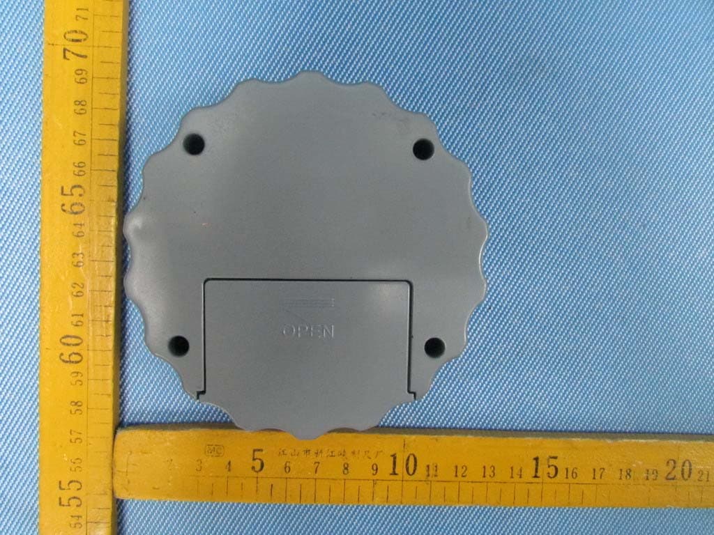
EUT –Front View EUT – Back View
ID Label/Location Info
FCC ID Label This device complies with Part 15 of the FCC Rules. Operation is subject to the following two conditions:(1) this device may not cause harmful interference,and (2) this device must accept any interference received, including interference that may cause undesired operation The Label must not be a stick-on paper. The Label on these products must be permanently affixed to the product and readily visible at the time of purchase and must last the expected lifetime of the equipment not be readily detachable. Proposed Label Location on EUT EUT Bottom View/proposed FCC Mark Location FCC ID: QE8423XXTX27 This device complies with part 15 of theFCC Rules.Operation is subject to the following
ID Label/Location Info
FCC ID Label Sample for Model: Snowmobile FCC ID: QE8423XXTX27 This device complies with Part 15 of the FCC Rules. Operation is subject to the following two conditions: (1) This device may not cause harmful interference, and (2) This device must accept any interference received, including interference that may cause undesired operation.
Internal Photos
PCB – Front View PCB– Back View
Test Report
FCC TEST REPORT Page 1 of 22 FCC ID : QE8423XXTX27 Applicant : Interactive Toy Concepts(HK) Ltd. 7/F.,Eu Yan San Tower, 11-15 Chatham Road South, TST, Kowloon, Hong Kong Equipment Under Test (EUT) : Product description : Snowmobile Model No. : Snowmobile Standards : FCC 15 Subpart C Paragraph 15.227 Date of Test : August 24,2006 Test Engineer : Tiger Su Reviewed By : PERPARED BY: Waltek Services (Shenzhen) Co., Ltd. 8C,West Tower, Aidi Building, No.5003 Binhe Rd, Futian District, Shenzhen 518045, Guangdong, China. Tel: 86-755-83551033 Fax: 86-755-83552400 Interactive Toy Concepts(HK) Ltd. FCC ID:QE8423XXTX27 2 Contents Page 1 COVER PAGE..........................................................................................................................................................1 2 CONTENTS..............................................................................................................................................................2 3 TEST SUMMARY....................................................................................................................................................5 4 GENERAL INFORMATION..................................................................................................................................6 4.1 CLIENT INFORMATION............................................................................................................................................6 4.2 GENERAL DESCRIPTION OF E.U.T...........................................................................................................................6 4.3 DETAILS OF E.U.T..................................................................................................................................................6 4.4 DESCRIPTION OF SUPPORT UNITS...........................................................................................................................6 4.5 STANDARDS APPLICABLE FOR TESTING..................................................................................................................6 4.6 TEST FACILITY........................................................................................................................................................7 4.7 TEST LOCATION......................................................................................................................................................7 5 EQUIPMENT USED DURING TEST...................................................................................................................8 6 CONDUCTED EMISSION TEST..........................................................................................................................9 6.1 TEST EQUIPMENT....................................................................................................................................................9 6.2 TEST PROCEDURE...................................................................................................................................................9 6.3 CONDUCTED TEST SETUP.....................................................................................................................................10 6.4 EUT OPERATING CONDITION...............................................................................................................................10 6.5 CONDUCTED EMISSION LIMITS.............................................................................................................................11 6.6 CONDUCTED EMISSION TEST RESULT...................................................................................................................11 7 RADIATION EMISSION TEST...........................................................................................................................12 7.1 TEST EQUIPMENT..................................................................................................................................................12 7.2 MEASUREMENT UNCERTAINTY.............................................................................................................................12 7.3 TEST PROCEDURE.................................................................................................................................................12 7.4 RADIATED TEST SETUP.........................................................................................................................................13 7.5 SPECTRUM ANALYZER SETUP...............................................................................................................................13 7.6 CORRECTED AMPLITUDE & MARGIN CALCULATION............................................................................................14 7.7 SUMMARY OF TEST RESULTS................................................................................................................................14 7.8 EUT OPERATING CONDITION...............................................................................................................................15 7.9 RADIATED EMISSIONS LIMIT.................................................................................................................................15 7.10 RADIATED EMISSIONS TEST RESULT................................................................................................................17 7.11 RADIATED EMISSION TEST DATA.....................................................................................................................17 8 OCCUPIED BANDWIDTH..................................................................................................................................18 8.1 TEST PROCEDURE.................................................................................................................................................18 9 PHOTOGRAPHS OF TESTING......................................................................................................…
Text truncated - open the document above for the full version.
Test Setup Photos
Radiation Emission Test View For 25MHz-1000MHz
Contact Information
Applicant
Virginia Yeung(General Manager)
Test Firm
Solid Industrial Co., Ltd.Yang Dengfang
Technical Specifications
| # | Rule Parts | Frequency Range | Power Output |
|---|---|---|---|
| 1 | 15C | 27.145 MHz - 27.145 MHz | - |
Other Applications from Interactive Toy Concepts Limited
QE822029TX
Aug 05, 20132.4G R/C Vehicle
Equipment Class
DXX - Part 15 Low Power Communication Device Transmitter
QE844077
Apr 15, 2012Wi-Spi Helicopter
Equipment Class
DTS - Digital Transmission System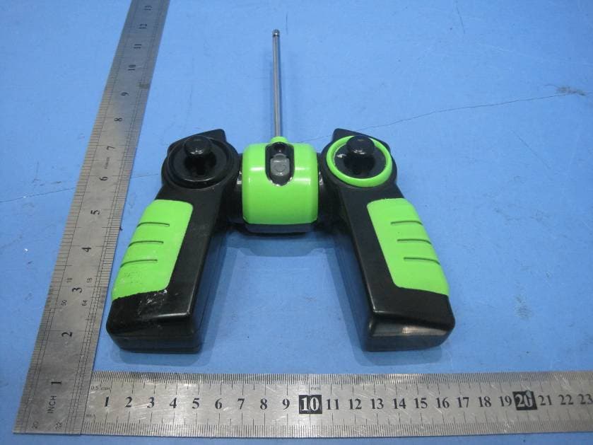
QE844072TX27
Mar 17, 2011RC CAR
Equipment Class
DXX - Part 15 Low Power Communication Device Transmitter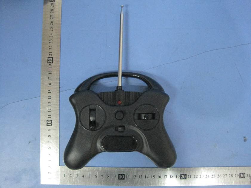
QE844070TX49
Jan 13, 2011RC PLANE
Equipment Class
DXX - Part 15 Low Power Communication Device Transmitter
QE844070TX27
Jan 13, 2011RC PLANE
Equipment Class
DXX - Part 15 Low Power Communication Device Transmitter