QE9LD-6LHAIP Locator
Quuppa Oy
Click to zoom
Application Details
- Equipment Class
- DTS - Digital Transmission System
- Date of Grant
- Jul 25, 2013
- Application Purpose
- Original Equipment
- Date of Application
- Jul 25, 2013
- Equipment Note
- HAIP Locator
- Frequency Range
- 2401.00000000 - 2481.00000000
- Company
- Quuppa Oy
- Country
- Finland
Documents & Files
Document Text
Text extracted from the exhibit documents filed with the FCC. Open a document above to read the original.
Users Manual
Quuppa LD-6L Installation Guide and Safety Information 1 Contents For your safety...............................................................................................3 1.Introduction................................................................................................4 About this document..................................................................................4 2.Get started.................................................................................................5 Parts............................................................................................................5 Quuppa LD-6L main unit...................................................................................6 Mounting Bracket.............................................................................................7 Connect to power supply............................................................................8 Option 1: Use Power over Ethernet (PoE).........................................................8 Option 2: Use separate 12V DC power supply..................................................8 Connect to HAIP network............................................................................8 Reset factory settings.................................................................................9 3.Installation.................................................................................................9 Safety Information......................................................................................9 Installing Quuppa LD-6L ...........................................................................10 Install mounting bracket to the ceiling/wall....................................................10 Install Quuppa LD-6L main unit to the mounting bracket...............................11 4.Product information..................................................................................13 5.Care and Maintenance.............................................................................14 Recycle.....................................................................................................14 6.Copyright and other notices.....................................................................15 2 Quuppa LD-6L Installation Guide and Safety Information © 2013 Quuppa For your safety Read these simple guidelines. Not following them may be dangerous or illegal. Read the complete installation guide for further information. SWITCH ON SAFETY Do not switch the device on when the use of wireless devices is prohibited of when it may cause interference or danger INTERFERENCE All wireless devices may be susceptible to interference, which could affect performance QUALIFIED SERVICE Only qualified personnel may install, configure, or repair this product ACCESSORIES Use only approved accessories. Do not connect incompatible products When connecting to any other device, read its user guide for detailed safety instructions. Do not connect incompatible products. 3 Quuppa LD-6L Installation Guide and Safety Information© 2013 Quuppa 1.Introduction Quuppa LD-6L (HAIP Locator) is a part of the Quuppa HAIP System. Other parts of the Quuppa HAIP system are Quuppa LD-6T (HAIP Tag) and Quuppa Positioning Engine software. The Quuppa HAIP System allows you to locate and track any objects equipped with HAIP Tags in an environment equipped with HAIP Locators. Read this guide carefully before having the Quuppa LD-6L professionally installed. Also, watch the Quuppa Site Planner and Quuppa Deployment tutorial videos before starting to use the HAIP system. For the latest guides, additional information, and downloads related to your Quuppa product, go to www.quuppa.com/support. This product may contain small parts. Keep them out of reach of small children. About this document Main features and first use of the Quuppa LD-6L are described in “Get started”, page 5. Installation to an indoor space is described in “Installation”, page 9. Quuppa LD-6L should only be installed by a qualified service technician using the original Quuppa parts supplied in the sales package. 4 Quuppa LD-6L Installation Guide and Safety Information© 2013 Quuppa 2.Get started Parts Quuppa LD-6L contains the following parts: 1.Quuppa LD-6L main unit 2.Quuppa LD-6L mounting bracket 5 Quuppa LD-6L Installation Guide and Safety Information© 2013 Quuppa Quuppa LD-6L main unit 1.Bracket mounting pins 2.Reset button 3.12V DC connector 4.Ethernet connector 5.Indicator lights 6 Quuppa LD-6L Installation Guide and Safety Information© 2013 Quuppa Mounting Bracket 1.Holes for ceiling/wall mounting screws 2.Holes for mounting bracket mounting pins 3.Safety lock 4.Orientation indicator 7 Quuppa LD-6L Installation Guide and Safety Information© 2013 Quuppa Connect to power supply Option 1: Use Power over Ethernet (PoE) Quuppa LD-6L supports the use of standard PoE (Power over Ethernet) components, e.g. PoE switch or power injector, as its power source. Only use standard certified PoE devices. When using PoE, a separate DC power supply is not required. Option 2: Use separate 12V DC power supply If you are not using PoE components, connect Quuppa LD-6L to an approved DC power supply using the DC connector. Only use compatible power supplies. Contact Quuppa in case of any uncertainty regarding compatible power supplies. When the power supply is connected Quuppa LD-6L automatically switches on. The blue indicator light flashes once, after which the red indicator light turns constantly on, until Quuppa LD-6L is connected to the HAIP System. Connect to HAIP network Connect Quuppa LD-6L to the HAIP System with Ethernet CAT5 UTP cable using the RJ-45 Ethernet socket. For your safety and to prevent any damage to Quuppa LD-6L, only connect Quuppa LD-6L to standard certified network components. The red indicator light is flashing when Quuppa LD-6L is properly connected to the HAIP System but not activated by the HAIP Positioning Engine software. Fo…
Text truncated - open the document above for the full version.
Cover Letter(s)
Qrrppcr Date: July LL,aOL3 Federal Communications Commission Authorization and Evaluation Division Subject: Short-term confidentialis request regarding application for certification of FCC lD: QEgtD-6t Purcuant to DA 04-1705 of the Commission's public notice, we request short-term confidential treatment fur the following information untilAug 24"20l.il in orderto ensure sensitive business information remains confidential until the actual marketing of the device. External Photos Test setup photos User's Manuol lnternol Photas Sincerely yours, Sincerely yours, Title: Chief Technology Otficer E-Moil: [email protected] Tel.: +358 50 §62746
Cover Letter(s)
C)rrppo Dote: July I I,2013 Federol Communicotions Commission Authorizotion ond Evoluotion Division Confidentiolity Request FCC ID: QE9LD.6L Pursuont to Sections 0.457 ond 0.459 of the Commission's Rules, the Applicont hereby requests confidentiol treotmeni of informotion occomponying this Applicotion os outlined below: Schemotics Block Diogrom The obove moteriols contoin lrode secrets ond proprietory informotion nol customorily releosed to the public. The public disclosure of these motters might be hormfulto the Applicont ond provide unjustified benefits to its competitors. The Applicont understonds lhot pursuont to Rule 0.457, disclosure of this Applicotion ond oll occomponying documentotion will not be mode before lhe dote of the Gront for this opplicotion. Sincerely yours, Antti Koinuloinen Title: Chief Technology Offtcer E-Moil : [email protected] Tel.: +358 50 4862746
Cover Letter(s)
Qrrppo Power of Attorney Dote: July I 1, 2013 To whom it moy concem: We, the undenigned Quuppa Oy hereby outhorize Bureou Veritos Consumer Products Services (H.K.) Ltd.. Tooyuon Bronch (BV CPS Tooyuon Bronch) of Toiwon to oct on our beholf in oll motters reloling to oll processes required in the FCC Port I5C opprovolond ony communicotion needed with the nolionol outhority. Any ond ollocts conied out by BV CPS Tooyuon Bronch on our beholf sholl hove the some effects os octs of our own. lf you hove ony questions regording the outhorizotion, pleose don't hesitote to contoct us. Thonk you! Sincerely yours, Antli Koinuloinen Title: Chief Technology Officer E-Moil : ontli.kqin uloinen @ouuooo.com Tel.: +358 50 4862746
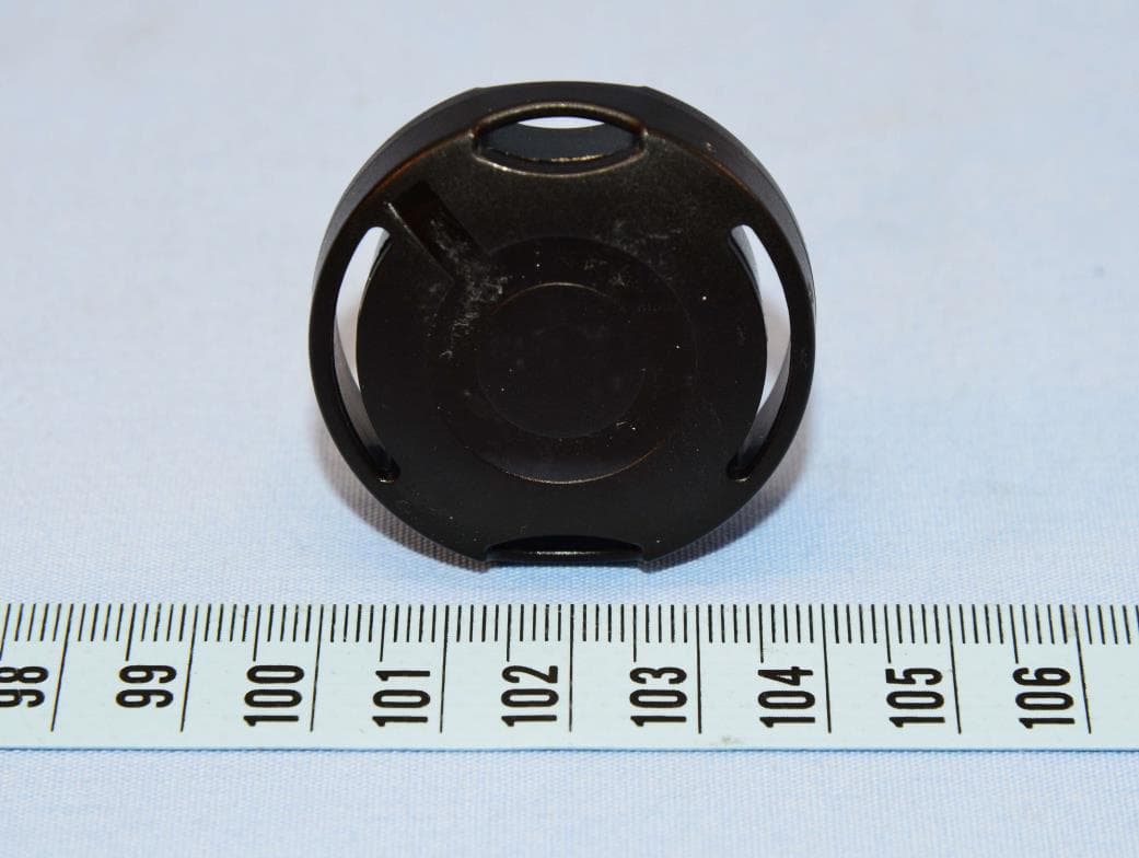
External Photos
Page: 1
Internal Photos
Page: 2 Page: 3 Page: 4 Page: 5 Page: 6
Operational Description
FCC ID: QE9LD-6L Report No.: RF120607D14B Operational Description The transmitter of the EUT (HAIP Locator) is powered by 12Vdc from AC adapter or 48Vdc from POE. The type of antenna is Printed antenna. The output power of this device is very low. Under normal use condition, the transmitter and the receiver are quite close, so high EIRP power is neither necessary nor allowed because of interference.
RF Exposure Info
Report No: SA120607D14B 1 of 6 Report Format Version 5.0.0 Reference No.: 130711D05 RF EXPOSURE REPORT REPORT NO.: SA120607D14B MODEL NO.: LD-6L FCC ID: QE9LD-6L RECEIVED: Jul. 11, 2013 TESTED: Jul. 14 ~ 23, 2013 ISSUED: Jul. 24, 2013 APPLICANT: Quuppa Oy ADDRESS: Otaniementie 19, FI-02150 Espoo, FINLAND ISSUED BY: Bureau Veritas Consumer Products Services (H.K.) Ltd., Taoyuan Branch LAB ADDRESS: No. 47, 14th Ling, Chia Pau Vil., Lin Kou Dist., New Taipei City 244, Taiwan (R.O.C.) This report is for your exclusive use. Any copying or replication of this report to or for any other person or entity, or use of our name or trademark, is permitted only with our prior written permission. This report sets forth our findings solely with respect to the test samples identified herein. The results set forth in this report are not indicative or representative of the quality or characteristics of the lot from which a test sample was taken or any similar or identical product unless specifically and expressly noted. Our report includes all of the tests requested by you and the results thereof based upon the information that you provided to us. You have 60 days from date of issuance of this report to notify us of any material error or omission caused by our negligence, provided, however, that such notice shall be in writing and shall specifically address the issue you wish to raise. A failure to raise such issue within the prescribed time shall constitute your unqualified acceptance of the completeness of this report, the tests conducted and the correctness of the report contents. Unless specific mention, the uncertainty of measurement has been explicitly taken into account to declare the compliance or non-compliance to the specification. Report No: SA120607D14B 2 of 6 Report Format Version 5.0.0 Reference No.: 130711D05 TABLE OF CONTENTS RELEASE CONTROL RECORD .................................................................................... 3 1. CERTIFICATION .............................................................................................. 4 2. EVALUATION RESULT ................................................................................... 5 3. SAR TEST EXCLUSION THRESHOLDS ......................................................... 6 4. CONCLUSION ................................................................................................. 6 Report No: SA120607D14B 3 of 6 Report Format Version 5.0.0 Reference No.: 130711D05 RELEASE CONTROL RECORD ISSUE NO. REASON FOR CHANGE DATE ISSUED SA120607D14B Original release Jul. 24, 2013 Report No: SA120607D14B 4 of 6 Report Format Version 5.0.0 Reference No.: 130711D05 1. CERTIFICATION PRODUCT: HAIP Locator BRAND NAME: Quuppa MODEL NO.: LD-6L APPLICANT: Quuppa Oy TESTED: Jul. 14 ~ 23, 2013 TEST SAMPLE: ENGINEERING SAMPLE STANDARDS: FCC Part 2 (Section 2.1093) FCC OET Bulletin 65, Supplement C (01-01) IEEE C95.1 The above equipment has been tested by Bureau Veritas Consumer Products Services (H.K.) Ltd., Taoyuan Branch, and found compliance with the requirement of the above standards. The test record, data evaluation & Equipment Under Test (EUT) configurations represented herein are true and accurate accounts of the measurements of the sample’s EMC characteristics under the conditions specified in this report. PREPARED BY : , DATE: Jul. 24, 2013 ( Jessica Cheng / Specialist ) APPROVED BY : , DATE: Jul. 24, 2013 ( Ken Liu / Senior Manager) Report No: SA120607D14B 5 of 6 Report Format Version 5.0.0 Reference No.: 130711D05 2. EVALUATION RESULT Following FCC KDB 447498 D01 “General SAR test exclusion guidance” The corresponding SAR Exclusion Threshold condition, listed below: 1) The 1-g and 10-g SAR test exclusion thresholds for 100 MHz to 6 GHz at test separation distances ≤ 50 mm are determined by: [(max. power of channel, including tune-up tolerance, mW)/(min. test separation distance, mm)] ·[√f(GHz)] ≤ 3.0 for 1-g SAR and ≤ 7.5 for 10-g extremity SAR,16 where ÿ f(GHz) is the RF channel transmit frequency in GHz . ÿPower and distance are rounded to the nearest mW and mm before calculation. ÿThe result is rounded to one decimal place for comparison The test exclusions are applicable only when the minimum test separation distance is ≤ 50 mm and for transmission frequencies between 100 MHz and 6 GHz. When the minimum test separation distance is < 5 mm, a distance of 5 mm is applied to determine SAR test exclusion. 2) At 100 MHz to 6 GHz and for test separation distances > 50 mm, the SAR test exclusion threshold is determined according to the following: a) [Threshold at 50 mm in step 1) + (test separation distance - 50mm)·( f(MHz)/150)] mW, at 100MHz to 1500 MHz b) [Threshold at 50 mm in step 1) + (test separation distance - 50 mm)·10] mW at > 1500 MHz and ≤ 6 GHz 3) At frequencies below 100 MHz, the following may be considered for SAR test exclusion. a) The threshold at the corresponding test separation distance at 100 MHz in step 2) is multiplied by [1 + log(100/f(MHz))] for test separation distances > 50 mm and < 200 mm. b) The threshold determined by the equation in a) for 50 mm and 100 MHz is multiplied by ½ for test separation distances ≤ 50 mm. c) SAR measurement procedures are not established below 100 MHz. When SAR test exclusion cannot be applied, a KDB inquiry is required to determine SAR evaluation requirements for any test results to be acceptable. Report No: SA120607D14B 6 of 6 Report Format Version 5.0.0 Reference No.: 130711D05 3. SAR TEST EXCLUSION THRESHOLDS Maximum measured transmitter power: Frequency (GHz) Max. Power (mW) Min. test separation distance (mm) SAR test exclusion calculation value (NOTE 2) 1-g SAR test exclusion thresholds Result 2.401 ~ 2.481 2.1 5 0.651 3 Pass NOTE: 1. The antenna type is Printed antenna with -6 dBi gain. 2. Calculate SAR test exclusion thresholds from condition “1” formulas. 4. CONCLUSION Since Source-base time average power is below SAR test exclusion power thresholds, the SAR evaluation …
Text truncated - open the document above for the full version.
Test Report
Report No.:RF120607D14B 1 of 42 Report Format Version 5.1.0 Reference No.: 130711D05 FCC TEST REPORT REPORT NO.: RF120607D14B MODEL NO.: LD-6L FCC ID: QE9LD-6L RECEIVED: Jul. 11, 2013 TESTED: Jul. 14 ~ 23, 2013 ISSUED: Jul. 24, 2013 APPLICANT: Quuppa Oy ADDRESS: Otaniementie 19, FI-02150 Espoo, FINLAND ISSUED BY: Bureau Veritas Consumer Products Services (H.K.) Ltd., Taoyuan Branch LAB ADDRESS: No. 47, 14th Ling, Chia Pau Vil., Lin Kou Dist., New Taipei City 244, Taiwan (R.O.C.) This report is for your exclusive use. Any copying or replication of this report to or for any other person or entity, or use of our name or trademark, is permitted only with our prior written permission. This report sets forth our findings solely with respect to the test samples identified herein. The results set forth in this report are not indicative or representative of the quality or characteristics of the lot from which a test sample was taken or any similar or identical product unless specifically and expressly noted. Our report includes all of the tests requested by you and the results thereof based upon the information that you provided to us. You have 60 days from date of issuance of this report to notify us of any material error or omission caused by our negligence, provided, however, that such notice shall be in writing and shall specifically address the issue you wish to raise. A failure to raise such issue within the prescribed time shall constitute your unqualified acceptance of the completeness of this report, the tests conducted and the correctness of the report contents. Unless specific mention, the uncertainty of measurement has been explicitly taken into account to declare the compliance or non-compliance to the specification. This report should not be used by the client to claim product certification, approval, or endorsement by TAF or any government agencies. Report No.:RF120607D14B 2 of 42 Report Format Version 5.1.0 Reference No.: 130711D05 TABLE OF CONTENTS RELEASE CONTROL RECORD ................................................................................... 4 1. CERTIFICATION ................................................................................................. 5 2. SUMMARY OF TEST RESULTS ......................................................................... 6 2.1 MEASUREMENT UNCERTAINTY ...................................................................... 6 3. GENERAL INFORMATION ................................................................................. 7 3.1 GENERAL DESCRIPTION OF EUT .................................................................... 7 3.2 DESCRIPTION OF TEST MODES ...................................................................... 8 3.2.1 TEST MODE APPLICABILITY AND TESTED CHANNEL DETAIL ...................... 9 3.3 DESCRIPTION OF SUPPORT UNITS .............................................................. 11 3.3.1 CONFIGURATION OF SYSTEM UNDER TEST ............................................... 12 3.4 GENERAL DESCRIPTION OF APPLIED STANDARDS ................................... 13 4. TEST TYPES AND RESULTS ........................................................................... 14 4.1 CONDUCTED EMISSION MEASUREMENT .................................................... 14 4.1.1 LIMITS OF CONDUCTED EMISSION MEASUREMENT.................................. 14 4.1.2 TEST INSTRUMENTS ...................................................................................... 14 4.1.3 TEST PROCEDURES ....................................................................................... 15 4.1.4 DEVIATION FROM TEST STANDARD ............................................................. 15 4.1.5 TEST SETUP .................................................................................................... 15 4.1.6 EUT OPERATING CONDITIONS ...................................................................... 16 4.1.7 TEST RESULTS ................................................................................................ 17 4.2 RADIATED EMISSION AND BANDEDGE MEASUREMENT ............................ 21 4.2.1 LIMITS OF RADIATED EMISSION AND BANDEDGE MEASUREMENT ......... 21 4.2.2 TEST INSTRUMENTS ...................................................................................... 22 4.2.3 TEST PROCEDURES ....................................................................................... 23 4.2.4 DEVIATION FROM TEST STANDARD ............................................................. 23 4.2.5 TEST SETUP .................................................................................................... 24 4.2.6 EUT OPERATING CONDITIONS ...................................................................... 24 4.2.7 TEST RESULTS ................................................................................................ 25 4.3 6DB BANDWIDTH MEASUREMENT ................................................................ 31 4.3.1 LIMITS OF 6DB BANDWIDTH MEASUREMENT ............................................. 31 4.3.2 TEST SETUP .................................................................................................... 31 4.3.3 TEST INSTRUMENTS ...................................................................................... 31 4.3.4 TEST PROCEDURE ......................................................................................... 31 4.3.5 DEVIATION FROM TEST STANDARD ............................................................. 31 4.3.6 EUT OPERATING CONDITIONS ...................................................................... 31 4.3.7 TEST RESULTS ................................................................................................ 32 4.4 CONDUCTED OUTPUT POWER ..................................................................... 33 4.4.1 LIMITS OF CONDUCTED OUTPUT POWER MEASUREMENT ...................... 33 4.4.2 TEST SETUP ...................................................................................…
Text truncated - open the document above for the full version.
Test Setup Photos
1 of 4 PHOTOGRAPHS OF THE TEST CONFIGURATION CONDUCTED EMISSION TEST – Mode A 2 of 4 CONDUCTED EMISSION TEST – Mode B 3 of 4 RADIATED EMISSION TEST – Mode A 4 of 4 RADIATED EMISSION TEST – Mode B
Contact Information
Applicant
Antti Kainulainen(CTO)
Test Firm
Bureau Veritas CPS (H.K.) Ltd., Taoyuan BranchRichard Chen
Technical Specifications
| # | Rule Parts | Frequency Range | Power Output |
|---|---|---|---|
| 1 | 15C | 2.40 GHz - 2.48 GHz | 2.00 mW |
Other Applications from Quuppa Oy
QE9QT3
Nov 21, 2022Tag
Equipment Class
DTS - Digital Transmission System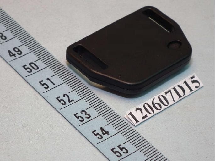
QE9LD-6T
Jul 25, 2013HAIP Tag
Equipment Class
DTS - Digital Transmission System