QE9QT3Tag
Quuppa Oy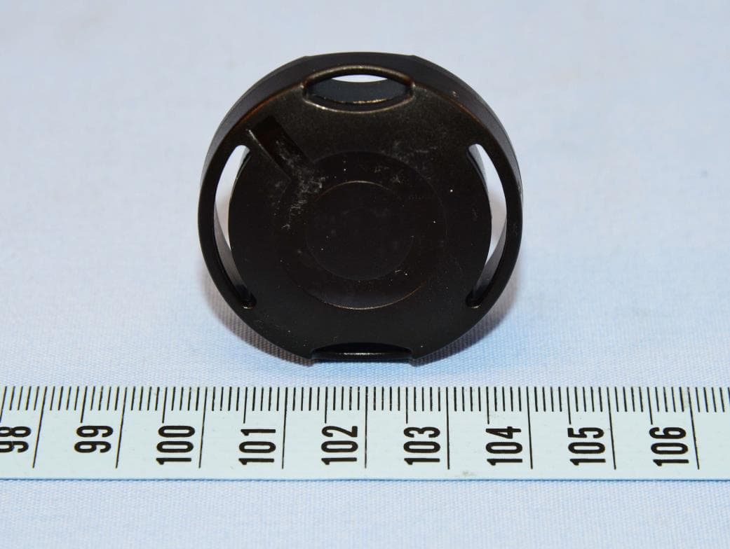
Click to zoom
Application Details
- Equipment Class
- DTS - Digital Transmission System
- Date of Grant
- Nov 21, 2022
- Application Purpose
- Original Equipment
- Date of Application
- Nov 21, 2022
- Equipment Note
- Tag
- Frequency Range
- 2402.00000000 - 2480.00000000
- Company
- Quuppa Oy
- Country
- Finland
Documents & Files
Document Text
Text extracted from the exhibit documents filed with the FCC. Open a document above to read the original.
Users Manual
QT3-1 Tag User Manual Updated: 06.09.2022 Release: DRAFT Contents Introduction......................................................................................................................................................3 QT3-1 Tag Features.........................................................................................................................................4 Using the QT3-1 Tag........................................................................................................................................5 Recycling and Disposal..................................................................................................................................9 QT3-1 Tag Certifications...............................................................................................................................10 FCC and IC Regulatory Statements........................................................................................................11 Copyright and Other Notices.......................................................................................................................13 Introduction The Quuppa QT3-1 (Quuppa Tag) is a tag that is compatible with the Quuppa Intelligent Locating System™. Other parts of the system are the Quuppa Locators and the Quuppa Positioning Engine (QPE) software. The Quuppa system allows you to locate and track any object equipped with a Quuppa Tag, a Quuppa compatible Tag or any Bluetooth enabled device emulating the Quuppa Tag, in an environment equipped with Quuppa Locators. Read this guide carefully and watch the Quuppa Academy videos before starting to use the system. For the latest guides, additional information related to your Quuppa product, go to quuppa.com/documentation. QT3-1 Tag User Manual © 2020-2022 Quuppa Oy. All rights reserved. The content provided is subject to change without notice. For the latest version, go to quuppa.com/documentation. Updated: 06.09.2022 | Release: DRAFT | Type: Highly Confidential 3 QT3-1 Tag Features The Quuppa QT3-1 has the following features: •4 mounting holes (1) •Button (2) •Red LED (3) •Waterproof casing •2.4 GHz radio SoC •Accelerometer •Pre-programmed with Quuppa Firmware QT3-1 Tag User Manual © 2020-2022 Quuppa Oy. All rights reserved. The content provided is subject to change without notice. For the latest version, go to quuppa.com/documentation. Updated: 06.09.2022 | Release: DRAFT | Type: Highly Confidential 4 Using the QT3-1 Tag This section covers how to use the Quuppa QT3-1. Please note that the Quuppa QT3-1 is compatible with Quuppa system release 8.0 or above. General Instructions Activating the QT3-1 Before using the Quuppa QT3-1 you must activate it and configure it for your Quuppa system. To activate the tag, use the Button Press method, i.e. press the button for 1 second to activate the Quuppa QT3-1. With the default configurations set for new QT3-1 tags, the tag will remain activated for 24 seconds after it becomes inactive before entering the storage mode again. Configuring the QT3-1 Tag configurations define the behaviour of the tags in your Quuppa system. For example, you can configure a tag to blink its LED light every time it enters a particular zone within your Quuppa system. Note: The LED blink uses a relatively large amount of power and so we recommend that to conserve the tag's battery, you only use the LED blink when necessary. New tags will be configured to use a default configuration. You can change this configuration to better suit the needs of your use case. To apply a new configuration, make sure that the tag is activated and use one of the following methods to send the new configuration to the tag: •Quuppa Site Planner (QSP) and a Focusing Locator •Quuppa Positioning Engine (QPE) API requests For more information, please refer to our product documentation available at quuppa.com/documentation. Attaching QT3-1 to a Locatable Object Attach the Quuppa QT3-1 to a locatable object. Important: For optimal operation do not attach Quuppa QT3-1 onto a large metallic surface. Warning: Never attach Quuppa QT3-1 onto hot surfaces. QT3-1 Tag User Manual © 2020-2022 Quuppa Oy. All rights reserved. The content provided is subject to change without notice. For the latest version, go to quuppa.com/documentation. Updated: 06.09.2022 | Release: DRAFT | Type: Highly Confidential 5 Important: Do not attach the Quuppa QT3-1 so that the button is permanently pressed down. Reset to Factory Settings To reset the device to factory settings hold the QT3-1 button side up and press the button until the LED turns off (5 seconds). While still pressing the button, turn the QT3-1 button side down. The LED will start blinking. Keep the button pressed for another 10 seconds until the LED stops blinking and turns continuously on. QT3-1 2D Barcode The backside of the QT3-1 includes a 2D barcode which contains the Tags ID number. The 2D barcode can be scanned for example with a separate 2D barcode reader or a suitable mobile phone app. You may need to select the setting “scan white barcode on black background” for optimal performance. Mechanical Details QT1-1 dimensions Dimensions (mm), front view: Dimensions (mm), side view: Waterproof casing Quuppa QT3-1 has IP protection class IP68. This means that it's dust and water resistant and can be immersed in 1.5 meters of freshwater for up to 30 minutes. Battery QT3-1 Tag User Manual © 2020-2022 Quuppa Oy. All rights reserved. The content provided is subject to change without notice. For the latest version, go to quuppa.com/documentation. Updated: 06.09.2022 | Release: DRAFT | Type: Highly Confidential 6 Quuppa QT3-1 has an in-built CR2354 battery. In normal operation the battery will last for several years. The battery voltage level can be monitored using the Quuppa system. Once the battery is discharged, Quuppa QT3-1 has to be recycled properly according to local regulations. Do not attempt to open the casing to replace the batt…
Text truncated - open the document above for the full version.
Cover Letter(s)
AGENCY AUTHORIZATION LETTER Date: 2022-10-04 FCC ID: QE9QT3 We, the undersigned, hereby authorize Andrea Hsia/ Supervisor of Bureau Veritas Consumer Products Services (H.K.) Ltd., Taoyuan Branch (BV CPS Taoyuan) of Taiwan to act on its behalf in all matters relating to the Federal Communication Commission (“FCC”) application for equipment authorization in connection with the FCC ID listed above, including signing of all documents relating to these matters. Any and all acts carried out by Andrea Hsia/ Supervisor of BV CPS Taoyuan on our behalf shall have the same effect as acts of our own. If you have any questions regarding the authorization, please don’t hesitate to contact us. Sincerely yours, ------------------------------------------------------- Antti Kainulainen Chief Technology Officer E-mail: [email protected] Tel.: +358504862746
External Photos
Reference No.:BGRJ-WTW-P22050612_ExtPho Page 1/3 CONSTRUCTION PHOTOS OF EUT Reference No.:BGRJ-WTW-P22050612_ExtPho Page 2/3 Reference No.:BGRJ-WTW-P22050612_ExtPho Page 3/3
ID Label/Location Info
FCC ID: QE9QT3 IC: 10657A-QT3 Label Location Back Side Label Location
ID Label/Location Info
FCC ID: QE9QT3 IC: 10657A-QT3 Label
Internal Photos
Reference No.:BGRJ-WTW-P22050612_IntPho Page 1/4 CONSTRUCTION PHOTOS OF EUT Reference No.:BGRJ-WTW-P22050612_IntPho Page 2/4 Reference No.:BGRJ-WTW-P22050612_IntPho Page 3/4 Reference No.:BGRJ-WTW-P22050612_IntPho Page 4/4
RF Exposure Info
SAR Test Report Report Format Version 5.0.0 Page No. : 1 of 25 Report No. : SFBGRJ-WTW-P22050612 Issued Date : Nov. 16, 2022 SAR Test Report Report No. : SFBGRJ-WTW-P22050612 Applicant : Quuppa Oy Address : Keilaranta 1, 8th floor, 02150 Espoo, Finland Product : Tag FCC ID : QE9QT3 Brand : Quuppa Model No. : QT3-1 FCC Rule Part CFR §2.1093 Standards : IEEE Std 1528:2013, KDB 865664 D01 v01r04, KDB 865664 D02 v01r02, KDB 447498 D01 v06 Sample Received Date : Oct. 18, 2022 Date of Testing : Nov. 15, 2022 Lab Address : No. 47-2, 14th Ling, Chia Pau Vil., Lin Kou Dist., New Taipei City, Taiwan Test Location : No. 19, Hwa Ya 2nd Rd., Wen Hwa Vil., Kwei Shan Dist., Taoyuan City, Taiwan CERTIFICATION: The above equipment have been tested by Bureau Veritas Consumer Products Services (H.K.) Ltd., Taoyuan Branch–Lin Kou Laboratories, and found compliance with the requirement of the above standards. The test record, data evaluation & Equipment Under Test (EUT) configurations represented herein are true and accurate accounts of the measurements of the sample’s SAR characteristics under the conditions specified in this report. It should not be reproduced except in full, without the written approval of our laboratory. The client should not use it to claim product certification, approval, or endorsement by TAF or any government agencies. Prepared By : Gina Liu / Specialist Approved By : Gordon Lin / Manager FCC Accredited No.: TW0003 This report is governed by, and incorporates by reference, the Conditions of Testing as posted at the date of issuance of this report at http://www.bureauveritas.com/home/about-us/our- business/cps/about-us/terms-conditions/ and is intended for your exclusive use. Any copying or replication of this report to or for any other person or entity, or use of our name or trademark, is permitted only with our prior written permission. This report sets forth our findings solely with respect to the test samples identified herein. The results set forth in this report are not indicative or representative of the quality or characteristics of the lot from which a test sample was taken or any similar or identical product unless specifically and expressly noted. Our report includes all of the tests requested by you and the results thereof based upon the information that you provided to us. Measurement uncertainty is only provided upon request for accredited tests. Statements of conformity are based on simple acceptance criteria without taking measurement uncertainty into account, unless otherwise requested in writing. You have 60 days from date of issuance of this report to notify us of any material error or omission caused by our negligence or if you require measurement uncertainty; provided, however, that such notice shall be in writing and shall specifically address the issue you wish to raise. A failure to raise such issue within the prescribed time shall constitute your unqualified acceptance of the completeness of this report, the tests conducted and the correctness of the report contents. SAR Test Report Report Format Version 5.0.0 Page No. : 2 of 25 Report No. : SFBGRJ-WTW-P22050612 Issued Date : Nov. 16, 2022 Table of Contents Release Control Record ............................................................................................................................................................... 3 1. Summary of Maximum SAR Value ....................................................................................................................................... 4 2. Description of Equipment Under Test ................................................................................................................................. 5 3. SAR Measurement System ................................................................................................................................................... 6 3.1 Definition of Specific Absorption Rate (SAR) ............................................................................................................... 6 3.2 SPEAG DASY6 System ............................................................................................................................................... 6 3.2.1 Robot ............................................................................................................................................................... 7 3.2.2 Probes ............................................................................................................................................................. 8 3.2.3 Data Acquisition Electronics (DAE) .................................................................................................................. 8 3.2.4 Phantoms ......................................................................................................................................................... 8 3.2.5 Device Holder .................................................................................................................................................. 9 3.2.6 System Validation Dipoles ............................................................................................................................. 10 3.2.7 Power Source ................................................................................................................................................ 10 3.2.8 Tissue Simulating Liquids .............................................................................................................................. 11 3.3 SAR System Verification ............................................................................................................................................ 13 3.4 SAR Measurement Procedure ................................................................................................................................... 14 3.4.1 Area Scan and Zoom Scan Procedure .............................................................…
Text truncated - open the document above for the full version.
RF Exposure Info
Plots of System Verification Appendix A. Plots of System Verification The plots for system verification are shown as follows. Plots of System Verification Test Laboratory: Bureau Veritas ADT SAR/HAC Testing Lab Date: 2022/11/15 S01 System Check_H2450_221115 DUT: Dipole 2450 MHz; Type: D2450V2; SN: 737 Communication System: UID 0, CW; Frequency: 2450 MHz;Duty Cycle: 1:1 Medium: H19T27N1_1115 Medium parameters used (interpolated): f = 2450 MHz; σ = 1.867 S/m; ε r = 37.958; ρ = 1000 kg/m 3 Ambient Temperature:23.6 °C ; Liquid Temperature:23.1 °C DASY5 Configuration: - Probe: EX3DV4 - SN7472; ConvF(7.89, 7.89, 7.89) @ 2450 MHz; Calibrated: 2022/05/27 - Sensor-Surface: 1.4mm (Mechanical Surface Detection) - Electronics: DAE3 Sn579; Calibrated: 2022/6/1 - Phantom: SAM Phantom_1982; Type: QD 000 P41 Ax; - Measurement SW: DASY52, Version 52.10 (4); SEMCAD X Version 14.6.14 (7501) Pin=50mW/Area Scan (81x81x1): Interpolated grid: dx=1.200 mm, dy=1.200 mm Maximum value of SAR (interpolated) = 4.44 W/kg Pin=50mW/Zoom Scan (7x7x7)/Cube 0: Measurement grid: dx=5mm, dy=5mm, dz=5mm Reference Value = 49.91 V/m; Power Drift = -0.01 dB Peak SAR (extrapolated) = 5.43 W/kg SAR(1 g) = 2.65 W/kg; SAR(10 g) = 1.29 W/kg (SAR corrected for target medium) Maximum value of SAR (measured) = 4.46 W/kg Plots of Measurement Appendix B. Plots of Measurement The SAR plots for highest measured SAR in each exposure configuration, wireless mode and frequency band combination are shown as follows. Plots of Measurement Test Laboratory: Bureau Veritas ADT SAR/HAC Testing Lab Date: 2022/11/15 P01 BT_Proprietary GFSK_Front Face_0mm_Ch80 DUT: BGRJ-WTW-P22050612 Communication System: UID 10032 - CAA, IEEE 802.15.1 Bluetooth (GFSK, DH5); Frequency: 2481 MHz;Duty Cycle: 1:1.31 Medium: H19T27N1_1115 Medium parameters used (interpolated): f = 2481 MHz; σ = 1.899 S/m; ε r = 37.887; ρ = 1000 kg/m 3 Ambient Temperature:23.6 °C ; Liquid Temperature:23.1 °C DASY5 Configuration: - Probe: EX3DV4 - SN7472; ConvF(7.89, 7.89, 7.89) @ 2481 MHz; Calibrated: 2022/5/27 - Sensor-Surface: 1.4mm (Mechanical Surface Detection) - Electronics: DAE3 Sn579; Calibrated: 2022/6/1 - Phantom: SAM Phantom_1982; Type: QD 000 P41 Ax; - Measurement SW: DASY52, Version 52.10 (4); SEMCAD X Version 14.6.14 (7501) Area Scan (71x71x1): Interpolated grid: dx=1.200 mm, dy=1.200 mm Maximum value of SAR (interpolated) = 0 W/kg Appendix Z. Calibration Certificate for Probe and Dipole The SPEAG calibration certificates are shown as follows. Model:D2450V2S/N:737Measurement Date:2022/8/25 Frequency (MHz) Type Item Previous Measurement Annual Check Deviation Accepted Tolerance Result Real Impedance 53.98951.387-2.602±5ΩPASS Imaginary Impedance 4.29265.36051.07±5ΩPASS Return Loss -24.989-24.145-3.38%±20%PASS 2450 Free Space 2450 MHz,Free Space Annual Confirmation of SAR Reference Dipole
Test Report
QT3-1 antenna measurement report Revision History2 Measurement description3 Measurement setup3 Measurement method3 Results4 Gain4 Max gain4 Antenna design5 Document name QT3-1 antenna measurement report Document number Creation date 2022-09-15 Last edit date 2022-11-18 Created by Niko Lindvall Approved by Ilari Teikari Classification PUBLIC Status PUBLISHED Version number 1.2 Page 1/5 Revision History Version number ChangesDatePerson 1.0First release15.9.2022NL 1.1Updated the correct dates to the footer7.10.2022IT 1.2Added measurement information14.11.2022IT Document name QT3-1 antenna measurement report Document number Creation date 2022-09-15 Last edit date 2022-11-18 Created by Niko Lindvall Approved by Ilari Teikari Classification PUBLIC Status PUBLISHED Version number 1.2 Page 2/5 1.Measurement description 1.1 Measurement setup The tag measurements are done using MVG SG 64, previously known as Satimo Stargate 64 (details). The system consists of an Anechoic chamber, where there are 64 measurement probes fed for both polarizations separately. The device under test is rotated 180 degrees on the rotator, so almost 360 degree 3d-pattern can be measured. Due to short measurement distance, the measurement result includes some near field term. MVG measurement software includes proprietary near field to far field conversion. This is optimized for the measurement setup and the system is calibrated according to the manufacturer instructions. 1.2 Measurement method Active measurement type is used. The tag under test is commanded to transmit sine wave (cw-test mode) on the measurement frequency on full power (ideally +6 dBm) and then the measurement cycle of Stargate is started. Frequency analyzer is used to receive the signal. The conductive CW power is then deducted from the measured equivalent power to extract the plain antenna gain. Document name QT3-1 antenna measurement report Document number Creation date 2022-09-15 Last edit date 2022-11-18 Created by Niko Lindvall Approved by Ilari Teikari Classification PUBLIC Status PUBLISHED Version number 1.2 Page 3/5 1.3 Measurement information Test engineer: Henry Sand Result analysis: Niko Lindvall Measurement equipment: MVG SG 64, Software: Satimo SMM 1.7.3 , Calibrated: 4.4.2022 2.Results 2.1 Gain 2.2 Max gain Maximum gain over full space is 2.5dBi Document name QT3-1 antenna measurement report Document number Creation date 2022-09-15 Last edit date 2022-11-18 Created by Niko Lindvall Approved by Ilari Teikari Classification PUBLIC Status PUBLISHED Version number 1.2 Page 4/5 3.Antenna design Antenna type: PIFA Antenna connector: None Document name QT3-1 antenna measurement report Document number Creation date 2022-09-15 Last edit date 2022-11-18 Created by Niko Lindvall Approved by Ilari Teikari Classification PUBLIC Status PUBLISHED Version number 1.2 Page 5/5
Test Report
Report No.: RFBGRJ-WTW-P22050612 Page No. 1 / 42 Report Format Version: 7.1.0 Reference No.: BGRJ-WTW-P22050612 TEST REPORT CERTIFICATE OF CONFORMITY Standard: 47 CFR FCC Part 15, Subpart C (Section 15.247) Report No.: RFBGRJ-WTW-P22050612 FCC ID: QE9QT3 Model No.: QT3-1 Received Date: 2022/5/11 Test Date: 2022/7/29 ~ 2022/8/3 Issued Date: 2022/9/30 Applicant: Quuppa Oy Address: Keilaranta 1, 8th floor, 02150 Espoo, Finland Issued By: Bureau Veritas Consumer Products Services (H.K.) Ltd., Taoyuan Branch Lin Kou Laboratories Lab Address: No. 47-2, 14th Ling, Chia Pau Vil., Lin Kou Dist., New Taipei City, Taiwan Test Location: No. 47-2, 14th Ling, Chia Pau Vil., Lin Kou Dist., New Taipei City, Taiwan FCC Registration / Designation Number: 198487 / TW2021 Approved by: , Date: 2022/9/30 Jeremy Lin / Project Engineer This test report consists of 42 pages in total. It may be duplicated completely for legal use with the approval of the applicant. It should not be reproduced except in full, without the written approval of our laboratory. The test results in the report only apply to the tested sample. The test results in this report are traceable to the national or international standards. Prepared by : Annie Chang / Senior Specialist This report is governed by, and incorporates by reference, the Conditions of Testing as posted at the date of issuance of this report at http://www.bureauveritas.com/home/about-us/our- business/cps/about-us/terms-conditions/ and is intended for your exclusive use. Any copying or replication of this report to or for any other person or entity, or use of our name or trademark, is permitted only with our prior written permission. This report sets forth our findings solely with respect to the test samples identified herein. The results set forth in this report are not indicative or representative of the quality or characteristics of the lot from which a test sample was taken or any similar or identical product unless specifically and expressly noted. Our report includes all of the tests requested by you and the results thereof based upon the information that you provided to us. Measurement uncertainty is only provided upon request for accredited tests. Statements of conformity are based on simple acceptance criteria without taking measurement uncertainty into account, unless otherwise requested in writing. You have 60 days from date of issuance of this report to notify us of any material error or omission caused by our negligence or if you require measurement uncertainty; provided, however, that such notice shall be in writing and shall specifically address the issue you wish to raise. A failure to raise such issue within the prescribed time shall constitute your unqualified acceptance of the completeness of this report, the tests conducted and the correctness of the report contents. Report No.: RFBGRJ-WTW-P22050612 Page No. 2 / 42 Report Format Version: 7.1.0 Reference No.: BGRJ-WTW-P22050612 Table of Contents Release Control Record ....................................................................................................................................................... 4 1 Certificate .................................................................................................................................................................... 5 2 Summary of Test Results .......................................................................................................................................... 6 2.1 Measurement Uncertainty ........................................................................................................................................ 6 2.2 Supplementary Information ...................................................................................................................................... 6 3 General Information ................................................................................................................................................... 7 3.1 General Description .................................................................................................................................................. 7 3.2 Antenna Description of EUT ..................................................................................................................................... 7 3.3 Channel List .............................................................................................................................................................. 7 3.4 Test Mode Applicability and Tested Channel Detail .................................................................................................. 8 3.5 Duty Cycle of Test Signal.......................................................................................................................................... 8 3.6 Test Program Used and Operation Descriptions ...................................................................................................... 9 3.7 Connection Diagram of EUT and Peripheral Devices .............................................................................................. 9 3.8 Configuration of Peripheral Devices and Cable Connections .................................................................................. 9 4 Test Instruments ...................................................................................................................................................... 10 4.1 RF Output Power .................................................................................................................................................... 10 4.2 Power Spectral Density .......................................................................................................................................... 10 4.3 6 dB Bandwidth ...................................................................................................................................................... 10 4.4 C…
Text truncated - open the document above for the full version.
Test Report
Report No.: RFBGRJ-WTW-P22050612-1 Page No. 1 / 35 Report Format Version: 7.1.0 Reference No.: BGRJ-WTW-P22050612 TEST REPORT CERTIFICATE OF CONFORMITY Standard: 47 CFR FCC Part 15, Subpart C (Section 15.247) Report No.: RFBGRJ-WTW-P22050612-1 FCC ID: QE9QT3 Model No.: QT3-1 Received Date: 2022/5/11 Test Date: 2022/7/29 ~ 2022/8/3 Issued Date: 2022/9/30 Applicant: Quuppa Oy Address: Keilaranta 1, 8th floor, 02150 Espoo, Finland Issued By: Bureau Veritas Consumer Products Services (H.K.) Ltd., Taoyuan Branch Lin Kou Laboratories Lab Address: No. 47-2, 14th Ling, Chia Pau Vil., Lin Kou Dist., New Taipei City, Taiwan Test Location: No. 47-2, 14th Ling, Chia Pau Vil., Lin Kou Dist., New Taipei City, Taiwan FCC Registration / Designation Number: 198487 / TW2021 Approved by: , Date: 2022/9/30 Jeremy Lin / Project Engineer This test report consists of 35 pages in total. It may be duplicated completely for legal use with the approval of the applicant. It should not be reproduced except in full, without the written approval of our laboratory. The test results in the report only apply to the tested sample. The test results in this report are traceable to the national or international standards. Prepared by : Annie Chang / Senior Specialist This report is governed by, and incorporates by reference, the Conditions of Testing as posted at the date of issuance of this report at http://www.bureauveritas.com/home/about-us/our- business/cps/about-us/terms-conditions/ and is intended for your exclusive use. Any copying or replication of this report to or for any other person or entity, or use of our name or trademark, is permitted only with our prior written permission. This report sets forth our findings solely with respect to the test samples identified herein. The results set forth in this report are not indicative or representative of the quality or characteristics of the lot from which a test sample was taken or any similar or identical product unless specifically and expressly noted. Our report includes all of the tests requested by you and the results thereof based upon the information that you provided to us. Measurement uncertainty is only provided upon request for accredited tests. Statements of conformity are based on simple acceptance criteria without taking measurement uncertainty into account, unless otherwise requested in writing. You have 60 days from date of issuance of this report to notify us of any material error or omission caused by our negligence or if you require measurement uncertainty; provided, however, that such notice shall be in writing and shall specifically address the issue you wish to raise. A failure to raise such issue within the prescribed time shall constitute your unqualified acceptance of the completeness of this report, the tests conducted and the correctness of the report contents. Report No.: RFBGRJ-WTW-P22050612-1 Page No. 2 / 35 Report Format Version: 7.1.0 Reference No.: BGRJ-WTW-P22050612 Table of Contents Release Control Record ....................................................................................................................................................... 4 1 Certificate .................................................................................................................................................................... 5 2 Summary of Test Results .......................................................................................................................................... 6 2.1 Measurement Uncertainty ........................................................................................................................................ 6 2.2 Supplementary Information ...................................................................................................................................... 6 3 General Information ................................................................................................................................................... 7 3.1 General Description .................................................................................................................................................. 7 3.2 Antenna Description of EUT ..................................................................................................................................... 7 3.3 Channel List .............................................................................................................................................................. 8 3.4 Test Mode Applicability and Tested Channel Detail .................................................................................................. 9 3.5 Duty Cycle of Test Signal.......................................................................................................................................... 9 3.6 Test Program Used and Operation Descriptions ..........................…
Text truncated - open the document above for the full version.
Contact Information
Applicant
Antti Kainulainen(CTO)
Test Firm
Bureau Veritas CPS(H.K.) Ltd., Taoyuan BranchLiu Ken
Technical Specifications
| # | Rule Parts | Frequency Range | Power Output |
|---|---|---|---|
| 2 | 15C | 2.40 GHz - 2.48 GHz | 4.00 mW |
Other Applications from Quuppa Oy

QE9LD-6L
Jul 25, 2013HAIP Locator
Equipment Class
DTS - Digital Transmission System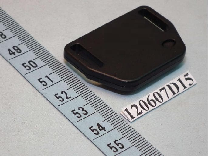
QE9LD-6T
Jul 25, 2013HAIP Tag
Equipment Class
DTS - Digital Transmission System