QHY800002-1Licensed Base Station
CommScope Technologies LLC
Click to zoom
Application Details
- Equipment Class
- PCB - PCS Licensed Transmitter
- Date of Grant
- Sep 25, 2003
- Application Purpose
- Original Equipment
- Date of Application
- Sep 25, 2003
- Equipment Note
- Licensed Base Station
- Frequency Range
- 1931.25000000 - 1988.75000000
- Company
- CommScope Technologies LLC
- Country
- United States
Documents & Files
Document Text
Text extracted from the exhibit documents filed with the FCC. Open a document above to read the original.
Users Manual
® Cover IP-RN 8000 Installation and Commissioning Guide Release 2.0 910056 Rev01d IP-RN 8000 Installation & Commissioning Guideiii IP-RN 8000 Installation and Commissioning Guide ivRelease 2.0, 910056 Rev01d Copyright 2002 and 2003 Airvana, Inc. All rights reserved. A irvana is a registered trademark of Airvana. AirVista is a trademark of Airvana. All other trademarks are t rademarks of their respective owners. This document contains information that is the property of Airvana, Inc. This document may not be copied, reproduced, reduced to any electronic medium or machine readable form, or otherwise duplicated, a nd the information herein may not be used, disseminated or otherwise disclosed, except with the prior written consent of Airvana, Inc. THE SPECIFICATIONS AND INFORMATION REGARDING THE PRODUCTS IN THIS MANUAL A RE SUBJECT TO CHANGE WITHOUT NOTICE. ALL STATEMENTS, INFORMATION, AND RECOMMENDATIONS IN THIS MANUAL ARE BELIEVED TO BE ACCURATE BUT ARE PRESENTED WITHOUT WARRANTY OF ANY KIND, EXPRESS OR IMPLIED. USERS MUST TAKE FULL RESPONSIBILITY FOR THEIR APPLICATION OF ANY PRODUCTS. THE SOFTWARE LICENSE AND LIMITED WARRANTY FOR THE ACCOMPANYING PRODUCT A RE SET FORTH IN THE INFORMATION PACKET THAT SHIPPED WITH THE PRODUCT AND A RE INCORPORATED HEREIN BY REFERENCE. IF YOU ARE UNABLE TO LOCATE THE SOFTWARE LICENSE OR LIMITED WARRANTY, CONTACT YOUR AIRVANA SALES REPRESENTATIVE FOR A COPY. IP-RN 8000 Installation & Commissioning Guidev Contents About this guide About this chapter ........................................................................................................................................... xiii Purpose............................................................................................................................................................. xiv Audience .......................................................................................................................................................... xiv Conventions ...................................................................................................................................................... xv Text conventions....................................................................................................................................... xv Icon conventions ..................................................................................................................................... xvii Related documentation ................................................................................................................................. xviii Release 2.0 document set...................................................................................................................... xviii Documentation CD-ROM......................................................................................................................... xx Release 2.0 online documentation ............................................................................................................ xx Airvana contact information ............................................................................................................................. xx Chapter 1 Introducing the IP-Radio Node 8000 Understanding the network ................................................................................................................................. 2 Understanding IP-RN 8000 front, side and back views...................................................................................... 3 Understanding the cabinet font view ......................................................................................................... 3 Understanding cabinet right side view........................................................................................................ 5 Understanding the cabinet back view ......................................................................................................... 7 Understanding access panels ...................................................................................................................... 9 Understanding module slot numbering............................................................................................................. 11 Understanding replaceability terms .................................................................................................................. 12 Understanding the Sector Radio Kit and the Antenna Interface Unit............................................................... 13 Understanding radio sectors...................................................................................................................... 13 Understanding the Sector Radio Kit ......................................................................................................... 14 Understanding the Radio Module ............................................................................................................. 14 Understanding the Power Amplifier module ............................................................................................ 16 Understanding the Antenna Interface Unit module.................................................................................. 17 Understanding the Digital Module Kit ............................................................................................................. 19 Understanding Digital Module Kit modules............................................................................................. 19 Understanding Digital Module Kit redundancy........................................................................................ 20 Understanding the Timing Frequency Unit module ................................................................................. 21 Understanding the Base Input Output/System Controller module ........................................................... 22 Understanding the 1xDOM module...........…
Text truncated - open the document above for the full version.
Users Manual
IP-RN 8000 Installation & Commissioning Guide103 Chapter 7 Installing modules About this chapter This chapter describes how to install all modules and contains these sections: •Understanding the module installation process on page 104 •Installing a Power Amplifier on page 105 •Installing a Radio Module on page 108 •Connecting the RM to the PA with the RF cable on page 111 •Connecting the Sector Radio Kit to the Antenna Interface Unit on page 113 •Installing a Timing Frequency Unit on page 116 •Installing a Base Input Output/System Controller on page 119 •Installing a 1xDOM on page 122 WRIST STRAP Wear an ESD strap when handling IP-RN 8000 modules. Chapter 7 ● Installing modules 104Release 2.0, 910056 Rev01d Understanding the module installation process This process explains all steps and procedures to follow when installing modules into the cabinet. 1.Installing Sector Radio Kit(s) These procedures explain how to install the two modules in a Sector Radio Kit. Repeat the procedures in this section for each sector in your installation. Typical installations support three sectors, but one or two sector installations are possible. In addition, several cable connections need to be made involving the Radio Module, the Power Amplifier module and the Antenna Interface Unit for each sector. Follow these steps for each Sector Radio Kit you install: a.See Installing a Power Amplifier on page 105. b.See Installing a Radio Module on page 108. c.See Connecting the RM to the PA with the RF cable on page 111. d.See Connecting the Sector Radio Kit to the Antenna Interface Unit on page 113. 2.Installing Digital Module Kit(s) These procedures explain how to install the three modules in a Digital Module Kit. •If you are installing a non-redundant node, follow these procedures once for the primary Digital Module Kit. •For redundant installations, follow these procedures twice, once for the primary Digital Module Kit and once for the redundant Digital Module Kit. a.See Installing a Timing Frequency Unit on page 116. b.See Installing a Base Input Output/System Controller on page 119. c.See Installing a 1xDOM on page 122. This procedure is complete. You must power the system on. Go to Powering the node on page 126. Installing a Power Amplifier IP-RN 8000 Installation & Commissioning Guide105 Installing a Power Amplifier This procedure explains how to install a Power Amplifier (PA) module. Be sure you have read and understood Understanding the module installation process on page 104 before continuing. Requirements •ESD wrist strap •Slotted screwdriver WARNING The PA weighs 22 pounds (10 kg). To avoid injury, use both hands when handling. Hold the module handle with one hand and place the other hand under the bottom module slide. WRIST STRAP Wear an ESD strap and plug it into the ESD jack in the AIU when handling modules or equipment damage can occur. See Figure 9 on page 18. CAUTION Ensure that you install the PA module into the proper slot (either slot 1 top part, slot 5 top part, or slot 9 top part). Installation into a slot reserved for a different module type can cause equipment damage. Chapter 7 ● Installing modules 106Release 2.0, 910056 Rev01d Procedure 1.Locate the slot into which you will install the PA module. The PA installs in the top part of slots 1, 5, and 9. See Understanding module slot numbering on page 11 for more information. 2.Align the PA with the module guides in the top and bottom of the slot of the appropriate sector. 3.Use the module handle to push the PA through the module guides and into the slot until you feel it touch the backplane. NOTE PA modules and RM modules pairs are installed in the top and bottom of the same vertical module slot. Top module guide Bottom module guide Installing a Power Amplifier IP-RN 8000 Installation & Commissioning Guide107 4.Hand tighten the top and bottom captive screws. 5.Use a slotted screwdriver to tighten the two captive screws to secure the PA into the chassis. Tighten screws snugly, but do not overtighten them or you might strip the threads. This procedure is complete. Go to Installing a Radio Module on page 108. Chapter 7 ● Installing modules 108Release 2.0, 910056 Rev01d Installing a Radio Module This procedure explains how to install a Radio Module (RM). Be sure you have read and understood Understanding the module installation process on page 104 before continuing. Requirements •ESD wrist strap •Slotted screwdriver Procedure 1.Locate the slot into which you will install the RM module. The RM installs in the bottom part of slots 1, 5, and 9. See Understanding module slot numbering on page 11 for more information. WRIST STRAP Wear an ESD strap and plug it into the ESD jack in the AIU when handling modules or equipment damage can occur. See Figure 9 on page 18. CAUTION Ensure that you install the RM module into the proper slot (either slot 1 bottom part, slot 5 bottom part, or slot 9 bottom part). Installation into a slot reserved for a different module type can cause equipment damage. Installing a Radio Module IP-RN 8000 Installation & Commissioning Guide109 2.Open the top and bottom latches on the RM module faceplate. 3.Align the RM with the module guides in the top and bottom of the slot of the appropriate sector. 4.Push the RM into the slot until you feel it touch the backplane. Chapter 7 ● Installing modules 110Release 2.0, 910056 Rev01d 5.Simultaneously, slowly close the top and bottom latches. As you close the latches, the RM module is drawn snugly into the chassis. Be sure the RM faceplate does not overlap the PA module. An overlap prevents proper module seating. 6.Hand tighten the top and bottom captive screws. 7.Use a slotted screwdriver to tighten the two captive screws to secure the RM into the chassis. Tighten screws snugly, but do not overtighten them or you might strip the threads. This procedure is complete. Go to Connecting the RM to the PA with the RF cable on page 111. Connecting the RM to the PA with the RF cable IP-RN 8000 Inst…
Text truncated - open the document above for the full version.
External Photos
REPORT: ED0658-1 FCC ID: QHY800002-1 EXHIBIT: “External” Photos MODEL: 800002 _____________________________________________________________ _____________________________________________________________ Curtis-Straus LLC • 527 Great Road • Littleton, MA • TEL (978) 486-8880 • FAX (978) 486-8828 Page 1 of 2 REPORT: ED0658-1 FCC ID: QHY800002-1 EXHIBIT: “External” Photos MODEL: 800002 _____________________________________________________________ _____________________________________________________________ Curtis-Straus LLC • 527 Great Road • Littleton, MA • TEL (978) 486-8880 • FAX (978) 486-8828 Page 2 of 2
Internal Photos
REPORT: ED0658-1 FCC ID: QHY800002-1 EXHIBIT: Internal Photos 1 MODEL: 800002 _____________________________________________________________ _____________________________________________________________ Curtis-Straus LLC • 527 Great Road • Littleton, MA • TEL (978) 486-8880 • FAX (978) 486-8828 Page 1 of 4 REPORT: ED0658-1 FCC ID: QHY800002-1 EXHIBIT: Internal Photos 1 MODEL: 800002 _____________________________________________________________ _____________________________________________________________ Curtis-Straus LLC • 527 Great Road • Littleton, MA • TEL (978) 486-8880 • FAX (978) 486-8828 Page 2 of 4 REPORT: ED0658-1 FCC ID: QHY800002-1 EXHIBIT: Internal Photos 1 MODEL: 800002 _____________________________________________________________ _____________________________________________________________ Curtis-Straus LLC • 527 Great Road • Littleton, MA • TEL (978) 486-8880 • FAX (978) 486-8828 Page 3 of 4 REPORT: ED0658-1 FCC ID: QHY800002-1 EXHIBIT: Internal Photos 1 MODEL: 800002 _____________________________________________________________ _____________________________________________________________ Curtis-Straus LLC • 527 Great Road • Littleton, MA • TEL (978) 486-8880 • FAX (978) 486-8828 Page 4 of 4
Internal Photos
REPORT: ED0658-1 FCC ID: QHY800002-1 EXHIBIT: Internal Photos 2 MODEL: 800002 _____________________________________________________________ _____________________________________________________________ Curtis-Straus LLC • 527 Great Road • Littleton, MA • TEL (978) 486-8880 • FAX (978) 486-8828 Page 1 of 4 REPORT: ED0658-1 FCC ID: QHY800002-1 EXHIBIT: Internal Photos 2 MODEL: 800002 _____________________________________________________________ _____________________________________________________________ Curtis-Straus LLC • 527 Great Road • Littleton, MA • TEL (978) 486-8880 • FAX (978) 486-8828 Page 2 of 4 REPORT: ED0658-1 FCC ID: QHY800002-1 EXHIBIT: Internal Photos 2 MODEL: 800002 _____________________________________________________________ _____________________________________________________________ Curtis-Straus LLC • 527 Great Road • Littleton, MA • TEL (978) 486-8880 • FAX (978) 486-8828 Page 3 of 4 REPORT: ED0658-1 FCC ID: QHY800002-1 EXHIBIT: Internal Photos 2 MODEL: 800002 _____________________________________________________________ _____________________________________________________________ Curtis-Straus LLC • 527 Great Road • Littleton, MA • TEL (978) 486-8880 • FAX (978) 486-8828 Page 4 of 4
Internal Photos
REPORT: ED0658-1 FCC ID: QHY800002-1 EXHIBIT: Internal Photos 3 MODEL: 800002 _____________________________________________________________ _____________________________________________________________ Curtis-Straus LLC • 527 Great Road • Littleton, MA • TEL (978) 486-8880 • FAX (978) 486-8828 Page 1 of 6 REPORT: ED0658-1 FCC ID: QHY800002-1 EXHIBIT: Internal Photos 3 MODEL: 800002 _____________________________________________________________ _____________________________________________________________ Curtis-Straus LLC • 527 Great Road • Littleton, MA • TEL (978) 486-8880 • FAX (978) 486-8828 Page 2 of 6 REPORT: ED0658-1 FCC ID: QHY800002-1 EXHIBIT: Internal Photos 3 MODEL: 800002 _____________________________________________________________ _____________________________________________________________ Curtis-Straus LLC • 527 Great Road • Littleton, MA • TEL (978) 486-8880 • FAX (978) 486-8828 Page 3 of 6 REPORT: ED0658-1 FCC ID: QHY800002-1 EXHIBIT: Internal Photos 3 MODEL: 800002 _____________________________________________________________ _____________________________________________________________ Curtis-Straus LLC • 527 Great Road • Littleton, MA • TEL (978) 486-8880 • FAX (978) 486-8828 Page 4 of 6 REPORT: ED0658-1 FCC ID: QHY800002-1 EXHIBIT: Internal Photos 3 MODEL: 800002 _____________________________________________________________ _____________________________________________________________ Curtis-Straus LLC • 527 Great Road • Littleton, MA • TEL (978) 486-8880 • FAX (978) 486-8828 Page 5 of 6 REPORT: ED0658-1 FCC ID: QHY800002-1 EXHIBIT: Internal Photos 3 MODEL: 800002 _____________________________________________________________ _____________________________________________________________ Curtis-Straus LLC • 527 Great Road • Littleton, MA • TEL (978) 486-8880 • FAX (978) 486-8828 Page 6 of 6
Internal Photos
REPORT: ED0658-1 FCC ID: QHY800002-1 EXHIBIT: Internal Photos 4 MODEL: 800002 _____________________________________________________________ _____________________________________________________________ Curtis-Straus LLC • 527 Great Road • Littleton, MA • TEL (978) 486-8880 • FAX (978) 486-8828 Page 1 of 6 REPORT: ED0658-1 FCC ID: QHY800002-1 EXHIBIT: Internal Photos 4 MODEL: 800002 _____________________________________________________________ _____________________________________________________________ Curtis-Straus LLC • 527 Great Road • Littleton, MA • TEL (978) 486-8880 • FAX (978) 486-8828 Page 2 of 6 REPORT: ED0658-1 FCC ID: QHY800002-1 EXHIBIT: Internal Photos 4 MODEL: 800002 _____________________________________________________________ _____________________________________________________________ Curtis-Straus LLC • 527 Great Road • Littleton, MA • TEL (978) 486-8880 • FAX (978) 486-8828 Page 3 of 6 REPORT: ED0658-1 FCC ID: QHY800002-1 EXHIBIT: Internal Photos 4 MODEL: 800002 _____________________________________________________________ _____________________________________________________________ Curtis-Straus LLC • 527 Great Road • Littleton, MA • TEL (978) 486-8880 • FAX (978) 486-8828 Page 4 of 6 REPORT: ED0658-1 FCC ID: QHY800002-1 EXHIBIT: Internal Photos 4 MODEL: 800002 _____________________________________________________________ _____________________________________________________________ Curtis-Straus LLC • 527 Great Road • Littleton, MA • TEL (978) 486-8880 • FAX (978) 486-8828 Page 5 of 6 REPORT: ED0658-1 FCC ID: QHY800002-1 EXHIBIT: Internal Photos 4 MODEL: 800002 _____________________________________________________________ _____________________________________________________________ Curtis-Straus LLC • 527 Great Road • Littleton, MA • TEL (978) 486-8880 • FAX (978) 486-8828 Page 6 of 6
Parts List/Tune Up Info
Part DescriptionQtyRef Des MODULE; RMC-1900 ASSY PCB; RDS WITH IF 1 RES; 360 OHM 5% 1/16W 0603 2 R329, R330 RES; 332 OHM 1% 1/16W 0603 5 R47, R50, R53, R63, R66 RES; 619 OHM 1% 1/16W 0603 1 R57 RES; 3.01 OHM 1% 1/16W 0603 12 R7, R8, R104-R106, R108, R109, R111, R351, R364-R366 RES; 2K OHM 1% 1/16W 0603 2 R150, R154 RES; 82 OHM 1% 1/16W 0603 1 R181 RES; 10K OHM 1% 1/16W 0603 4 R51, R74, R176, R177 RES; 150 OHM 1% 1/16W 0603 3 R178-R180 RES; 2.7K OHM 1% 1/16W 0603 1 R119 RES; 453 OHM 1% 1/16W 0603 6 R9, R107, R110, R112, R367, R368 RES; 221 OHM 1% 1/16W 0603 1 R62 RES; 22K OHM 5% 1/10W 0805 1 R309 RES; 1K OHM 1% 1/16W 0603 12 R30, R48, R49, R52, R54, R56, R61, R64, R65, R73, R149, R152 RES; 0 OHM; 5%; 1/16W; 0603 16 R29, R59, R97, R190, R191, R299, R302, R304, R311, R314, R349, R350, R370, R373, R375, R379 RES; 100 OHM 5% 1/16W 0603 33 R26, R159, R225-R244, R249-R254, R263, R294-R297 RES; 1K OHM; 5%; 1/16W; 0603 14 R55, R101, R102, R188, R193, R245, R255-R258, R260, R266, R289, R298 RES; 11K OHM 5% 1/16W 0603 4 R91-R94 RES; 1.3K OHM 5% 1/16W 0603 1 R60 RES; 16 OHM 5% 1/16W 0603 2 R103, R113 RES; 200 OHM 5% 1/16W 0603 5 R96, R114, R116, R182, R183 RES; 2.2K OHM 5% 1/16W 0603 7 R16, R21, R82, R87, R88, R171, R371 RES; 24K OHM 5% 1/16W 0603 2 R135, R136 RES; 2.7K OHM 5% 1/16W 0603 4 R316, R318, R319, R343 RES; 3K OHM 5% 1/16W 0603 2 R89, R90 RES; 33 OHM; 5%; 1/16W; 0603 33 R195, R223, R224, R246-R248, R267-R287, R290, R291, R293, R306, R307, R317 RES; 3.6K OHM 5% 1/16W 0603 2 R155, R156 RES; 4.7K OHM; 5%; 1/16W; 0603 18 R27, R35, R115, R137-R140, R151, R153, R172, R300, R301, R337, R338, R362, R363, R378, R381 RES; 51 OHM; 5%; 1/16W; 0603 3 R95, R141, R142 RES; 510 OHM; 5%; 1/16W; 0603 16 R36, R43, R58, R81, R128, R129, R143-R148, R170, R184, R376, R377 RES; 100.0 1% 0805(125mW) +/-100PPM CHIP THK F 1 R352 RES; 1M OHM 1% 1/10W 0805 2 R344, R345 RES; 301 OHM 1% 1/10W 0805 3 R346-R348 RES; 0 OHM; 5%; 0805; (125mW) +/- 200 PPM; CHIP THK F 8 R331-R334, R336, R339-R341 RES; 1.5K; 5%; 0805; (125mW) +/- 200PPM; CHIP THK F 3 R325-R327 RES; 160 5% 0805(125mW) +/-200PPM CHIP THK F 9 R353-R361 RES; 4.7K 5% 0805(125mW) +/-200PPM CHIP THK F 37 R14, R15, R17-R20, R37, R40-R42, R44-R46, R67-R72, R75-R80, R100, R157, R158, R167-R169, R173, R192, R196, R197, R259, R261 RES; 510 5% 0805(125mW) +/-200PPM CHIP THK F 43 R1-R5, R83-R86, R98, R99, R174, R185-R187, R189, R194, R198-R222, R315 RES; 24 OHM 5% 1/4W 1210 15 R120-R127, R130-R133, R160, R175, R313 RES; 13 OHM 5% 1/2W 2010 2 R262, R264 RES NTWK; THIN FILM 10K 2% +/-100PPM 23-RES BUSS THIN FILM 6 RN1-RN6 RES NTWK; 4 RES 33 OHM 5% 63mW PER RES ISOLATED 39 RN7, RN9-RN12, RN14-RN23, RN26, RN28-RN30, RN34, RN37-RN52, RN75-RN77 RES NTWK; 4 RES 510 OHM 5% 63mW PER RES ISOLATED 10 RN8, RN13, RN24, RN25, RN53-RN55, RN57, RN67, RN68 RES NTWK; 4 RES 1K OHM 5% 63mW PER RES ISOLATED 13 RN31-RN33, RN56, RN58-RN66 RES NTWK; 4 RES 4.7K OHM 5% 63mW PER RES ISOLATED 7 RN27, RN69-RN74 CAP; CER 10PF 5% COG/NP0 50V 4 C378-C380, C383 CAP; CER .010UF 10% X7R 50V 63 C11, C48, C209-C225, C227-C254, C261-C272, C283, C375-C377 CAP; CER 470PF 10% X7R 50V 9 C15-C21, C273, C274 CAP; CER 0.1UF 10% X7R 25V 0603 198 C9, C10, C12-C14, C22-C47, C49-C95, C97-C99, C106, C109-C122, C124-C128, C130, C131, C150, C171, C195, C196, C203, C226, C258, C275-C282, C284, C285, C290-C303, C305-C364, C366, C381, C382, C384 CAP; CER 1000PF NPO 5% 25V 0603 13 C100-C105, C107, C108, C185, C186, C197-C199 CAP; CER 220PF NPO 5% 50V 0603 2 C370, C371 CAP; CER 3.9PF NPO +/-.25pF 50V 0603 2 C172, C173 CAP; CER 22PF NPO 5% 50V 0603 1 C123 CAP; CER 30PF NPO 1% 50V 0603 2 C96, C179 CAP; CER 68PF NPO 1% 50V 0603 1 C169 CAP; CER 18PF NPO 1% 50V 0603 5 C132-C135, C187 CAP; CER 27PF NPO 1% 50V 0603 3 C2, C4, C170 CAP; CER 8200PF X7R 5% 16V 0603 2 C174, C175 CAP; TANT 22UF 20% 35V LOW ESR 7343H 1 C129 CAP; CER 22PF NPO +/-.25PF 50V 0603 6 C1, C168, C200-C202, C287 CAP; CER 10PF NPO +/-.25pF 50V 0603 6 C5-C8, C206, C207 CAP; CER 12PF NPO +/-.25pF 50V 0603 1 C176 CAP; CER 100PF NPO 1% 50V 0603 2 C183, C184 CAP; CER 20PF NPO 2% 50V 0603 1 C205 CAP; CER 82PF NPO 2% 50V 0603 2 C3, C190 CAP; CER 0.1uF X7R 5% 25V 0805 1 C204 CAP; CER 1uF X7R 10% 50V 1812 2 C372, C373 CAP; TANT 1.0UF 10% 16V,3216 2 C182, C255 CAP; TANT 10UF 10% 16V 26 C136-C140, C142-C146, C149, C151, C153-C155, C160-C164, C181, C191-C194, C365 CAP; TANT 10UF 10% 20V 6032 9 C141, C147, C148, C152, C156, C159, C165, C188, C189 CAP; TANT 15UF 10% 16V 6032 4 C157, C158, C166, C167 CAP; TANT 22UF 10% 10V 6032 3 C177, C178, C180 CAP; TANT 220UF 10% 6V 7343H 4 C208, C367-C369 IC; LVC 2 INPUT OR GATE; -40 TO 85 C 5-PIN SC70 1 U68 IC; FPGA EP1K50 ACEX1K SERIES; -40+85C 144TQFP 1 U80 IC; DUAL HDLC; -40 TO +85C 100TQFP 1 U66 IC; SRAM; 64KX16 3.3V 15NS -40 TO +85C 44TSOP 2 U33, U34 IC; ZERO DELAY BUFFER DIV; 2 3.3V -40+85C 8SOIC 2 U44, U82 IC; LVC SINGLE BUFFER 3STATE; -40+85C 5PIN SSOP 1 U87 IC; ZERO DELAY BUFFER NINE OUTPUTS; -40 TO 85C 16 TSSOP 1 U32 IC; ZERO DELAY BUFFER; 3.3V -40+85C 8SOIC 3 U45, U47, U64 IC; RS485 1TX 1RX 3.3V IND TEMP SO8 4 U25, U29, U42, U43 IC; DUAL MONOSTABLE; -40+70C 16TSSOP 2 U89, U90 IC; PWR MONITOR 1 U65 IC; MICROCONTROLLER; 3V 33MHZ -40 TO 85C 144 LQFP 1 U67 IC; PLD; EP1K10 ACEX1K FAMILY 144 TQFP 1 U79 IC; TTL TO DIFFERENTIAL LVDS QUAD DRIVER 3 U48-U50 IC; TTL TO DIFFERENTIAL LVDS QUAD RECEIVER 9 U51-U59 IC; DIGITAL DOWN CONV; 3.3V -40 TO 85C 196LBGA 1 U78 IC; XSTR; 160V 6000MA SOT-23 3 Q1-Q3 IC; COMPARATOR DUAL LOW POWER LOW OFFSET 8 SOIC 1 U22 IC; OP AMP; 25 MHZ BW -40 TO 85C 8 SOIC 1 U23 SWITCH; PUSH BUTTON RT ANG PC THRU-HOLE 1 SW1 SWITCH; SPST 4 SWITCH POSITION 8 PIN SMT 1 SW4 IC; VREG; 500MA LDO ADJ OUT -40 TO 125C TO-263-5 1 U35 IC; VREG; 800MA LDO ADJ OUT 8 SOIC 8 U1-U7, U36 IC; PHASE DETECTOR; 800 MHZ BW -40 TO 70C 8 SOIC 1 U9 IC; PLL CLOCK DRIVER; 25-110MHZ 0 TO 70C 32 LQFP 1 U17 IC; 2:1 MUX 1 U39 IC; LV SINGLE LVDS DRIV/REC; 3.3V OR 5V -40 TO 85C 14 SOIC 2 U40, U41 IC; LVC OCTAL D REGISTER; 3 STATE OUTPUT 20 SOIC 1 U70 IC; ALVCH …
Text truncated - open the document above for the full version.
Test Report
Test Report Report No ED0658-1 Client Airvana 25 Industrial Ave. Chelmsford, MA 01824 Phone 978-250-3028 Fax 978-250-3910 FRN 0007380173 Model 800002 FCC ID QHY800002-1 Equipment Type Licensed base station for Part 24 Equipment Code PCB Results As detailed within this report Prepared by _____________________ Evan Gould – Test Engineer Authorized by __________________________ Michael Buchholz – EMC Manager Issue Date 9/5/03 Conditions of issue This Test Report is issued subject to the conditions stated in ‘terms and conditions’ section of this report. Curtis-Straus LLC is accredited by the American Association for Laboratory Accreditation for the specific scope of accreditation under Certificate Number 1627-01. This report may contain data which is not covered by the A2LA accreditation. _____________________________________________________________ Curtis-Straus LLC • 527 Great Road • Littleton, MA • TEL (978) 486-8880 • FAX (978) 486-8828 REPORT: ED0658-1 FCC ID: QHY800002-1 _____________________________________________________________ Table Of Contents Summary..............................................................................................................3 Test Methodology.................................................................................................3 Statement of Conformity.......................................................................................4 Conducted Peak Output Power............................................................................5 Conducted Spurious and Band Edges..................................................................6 Radiated Spurious Emissions...............................................................................7 Frequency Stability...............................................................................................8 Bandwidth Measurements....................................................................................9 Test Equipment Used.........................................................................................12 Terms And Conditions........................................................................................13 A2LA Accreditation.............................................................................................15 _____________________________________________________________ Curtis-Straus LLC • 527 Great Road • Littleton, MA • TEL (978) 486-8880 • FAX (978) 486-8828 Page 2 of 17 REPORT: ED0658-1 FCC ID: QHY800002-1 _____________________________________________________________ Summary This technical report supports an application for certification of a transmitter operating pursuant to 47 CFR 24 Subpart E – Broadband PCS. The product is the RM-1900 Radio Module card (model #: 800002), which is used in conjunction with the RN 8000 base station. This product has been certified before under the FCC ID: QHY800002. The product was modified as follows: The local oscillator (synthesizer) that provides the final upconversion to the RF transmit frequency was modified to improve (decrease) close-in phase noise. This was done by adding/changing component values in the synthesizer loop filter to decrease its bandwidth and reduce its self-noise generation. The new proposed FCC ID is QHY800002-1 Test Methodology Radiated emissions testing is performed according to the procedures specified in ANSI C63.4 (2000). Frequency Range Investigated Measurement Distance 30-1000MHz 3m 1-18GHz 3m 18-20GHz 1m The EUT’s power level was set to it’s maximum value of 43dBm. Radiated spurious emissions was performed with the (male N-type) antenna port terminated. The product was rotated around the vertical axis with the door closed. _____________________________________________________________ Curtis-Straus LLC • 527 Great Road • Littleton, MA • TEL (978) 486-8880 • FAX (978) 486-8828 Page 3 of 17 REPORT: ED0658-1 FCC ID: QHY800002-1 _____________________________________________________________ Statement of Conformity Part 2 Part 15 Comments 2.925 The label is shown in the label exhibit. It is attached to the side of the Radio Module and is visible during installation. 2.1033(c)(5) EUT operates in the frequency range 1931.25-1988.75MHz (Channels 25-1175; See attached Channel Plan) 2.1033(c)(8) The power into the RF power amplifier is in the range 24Vdc - 30Vdc and should not exceed 16A. 2.1033(c)(9) Output level is set via software up to the value at which the report data was taken. Airvana indicates this device has no tune-up procedure but output is verified after installation via a PA offset calibration. 2.1046 24.232 The EUT meets the peak output power limit specified in 24.232. 2.1049 Measurements were taken of the Occupied (99%) Bandwidth. 2.1055 24.235 Frequency stability with regard to temperature and voltage variations is sufficient to ensure that the fundamental emission will stay within the authorized frequency block. 2.1051 24.238 All spurious emissions outside the authorized frequency block meet the limit specified in 24.238. See the attached manual exhibit with RF exposure warnings on pages 45 and 87. _____________________________________________________________ Curtis-Straus LLC • 527 Great Road • Littleton, MA • TEL (978) 486-8880 • FAX …
Text truncated - open the document above for the full version.
Contact Information
Applicant
Zac Johnson(Regulatory Engineer)
Test Firm
Curtis-Straus LLCJonathan Stewart
Technical Specifications
| # | Rule Parts | Frequency Range | Power Output | Emission | Tolerance |
|---|---|---|---|---|---|
| 1 | 24E | 1.93 GHz - 1.99 GHz | 10 W | 1M43D7D | 8400.0000000000 Hz |
Other Applications from CommScope Technologies LLC
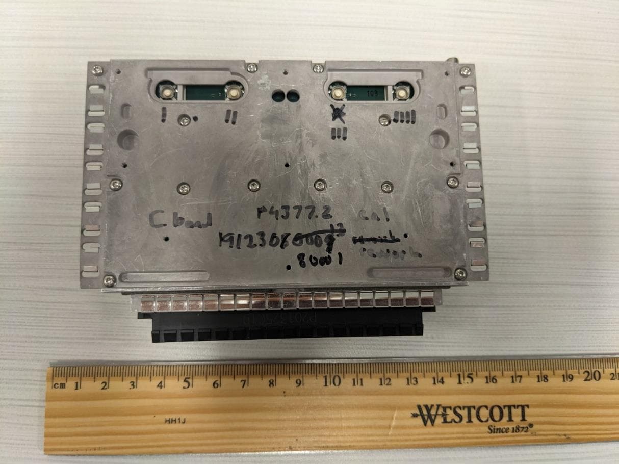
QHYRPM-A5A11-N77
May 01, 2023The OneCell RP5200 5G Band n77, BW, P3 rev
Equipment Class
TNB - Licensed Non-Broadcast Station Transmitter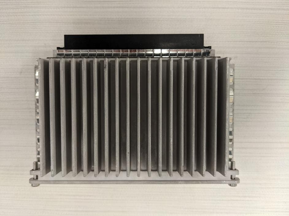
QHYRPM-A5A11-N77C
Aug 30, 2022The OneCell RP5200 5G Band n77, 40MHz BW
Equipment Class
TNB - Licensed Non-Broadcast Station Transmitter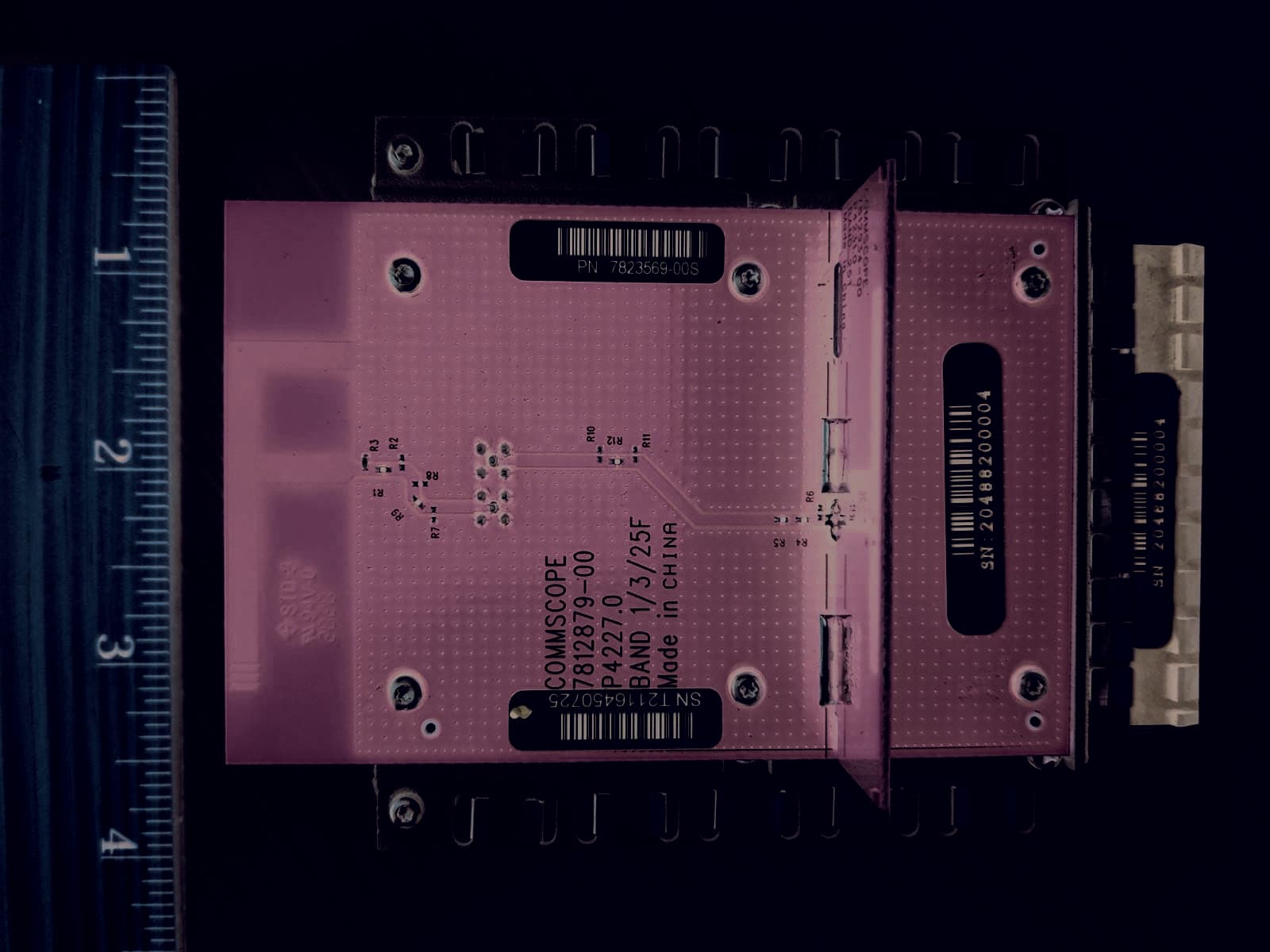
QHYRPM-A5A11-B25
Apr 04, 2022The OneCell RP5200 B25 / B2 Radio.
Equipment Class
PCB - PCS Licensed Transmitter
QHYRPM-A5A11-B30
Dec 15, 2020The OneCell RP5100 LTE Band 30
Equipment Class
TNB - Licensed Non-Broadcast Station Transmitter
QHYRPM-A5A11-B05
Dec 02, 2020The OneCell RP5100 LTE Band 5
Equipment Class
TNB - Licensed Non-Broadcast Station Transmitter