QITBT01Bluetrek Bluetooth Wireless Headset
ConnecteDevice Limited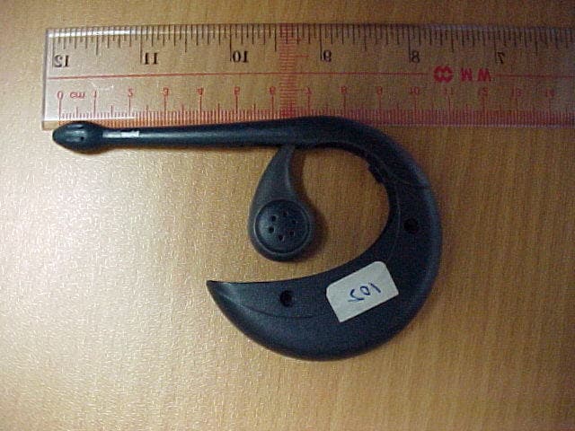
Click to zoom
Application Details
- Equipment Class
- DSS - Part 15 Spread Spectrum Transmitter
- Date of Grant
- Oct 08, 2002
- Application Purpose
- Original Equipment
- Date of Application
- Oct 08, 2002
- Equipment Note
- Bluetrek Bluetooth Wireless Headset
- Frequency Range
- 2402.00000000 - 2480.00000000
- Company
- ConnecteDevice Limited
- Country
- Hong Kong
Documents & Files
Document Text
Text extracted from the exhibit documents filed with the FCC. Open a document above to read the original.
Users Manual
Bluetrek Bluetooth Wireless Headset for mobile phones User Guide FCC Statement This device complies with Part 15 of the FCC Rules. Operation is subject to the following two conditions : (1) This device may not cause harmful interference, and (2) This device must accept any interference received, including interference that may cause undesired operation. Caution : Changes or modifications to this Bluetooth headset not expressly approved by the manufacturer could void the user's authority to operate the equipment. 1. Introduction BlueTrek is a wireless Headset for mobile phones. It uses the Bluetooth Technology, a new standard for wireless short distance radio communications. Devices like a headset and a mobile phone can communicate with each other without wires within approximately 10 meters. BlueTrek Headset is a qualified Bluetooth headset that complies with the Bluetooth 1.1 protocol. Bluetrek can be used with: - A qualified BlueTooth Mobile Phone; - A non-Bluetooth mobile Phone when used with the BT07 adaptor (optional). To check the list of qualified Bluetooth Mobile Phones working with Bluetrek, please consult: www.bluetrek.com Your package includes: - Bluetrek Headset - Headset charger - Headset carrying case with belt clip (optional) 2. BlueTrek Headset FIGURE 1 Dual colour light - Switch on - Pairing mode - Take a call - Volume Up - End a call - Switch off (together with button2) - Take a call - Volume Down - End a call - Switch off (together with button 1) Charging plug 1 2 3. Charging BlueTrek Your Headset is delivered uncharged. So before you start to use Bluetrek, you must fully recharge it for about 2 hours. It is mandatory to use the charger provided with your product. The use of any other charger will automatically suspend the warranty. Plug the charger jack into the Headset. Because the jack is new, it is harder to plug when you start to use it. So please make sure you push it completely. During the charge (about 2 hours), the Headset light will be red and continuously on. Once the charge is completed, the light with turn to green. You can now use your headset. When you hear a beep in your Headset at regular intervals or approximately 1 minute, your Headset needs to be recharged. It is recommended to recharge your headset to full capacity once a day, until the light turns to green. During the charge you still can use your headset. The Headset is using a rechargeable battery that has a life of about 500 charging cycles. Once the talk-time of your Headset is reduced significantly, contact your vendor for battery replacement. The battery must be disposed of properly and may need to be recycled. Please contact your local recycling for proper disposal. Do not dispose of batteries in fire as they may explode. Microphone Adjustable speaker 4. Pairing Bluetrek headset to a Bluetooth mobile phone Before using the BlueTrek Headset, you must pair it with your BlueTooth mobile phone. Pairing is the process of linking two BlueTooth devices, so that they can communicate. The pairing only needs to be done once. Afterwards, every time you switch on your Headset, it will automatically connect to your mobile phone. If you pair your Bluetooth mobile phone with another Bluetooth device, you will have to pair the Bluetrek Headset with your phone again before use. IMPORTANT: before pairing, all Bluetooth devices have to be switched off. To initiate a pairing, put both the Headset and the mobile phone within 1 meter (3 feet) from each other. 1- Switch on your phone and select the BlueTooth discover mode (or sniff mode) on the Mobile Phone (See the BlueTooth Mobile Phone user’s manual) 2- Press the ON button (See Button 1 on Figure 1) on the Headset and keep it pressed for about 8 seconds. (Remark: After 3 seconds, the light with flash green and red and you will hear a music tone in the speaker; Do not release the button at that time! Only after 8 seconds, when the light flashes only in red and you can hear a lighter tone, can you release the button). 3- Once the mobile phone detects the headset, a message is displayed with the following information: Bluetrek 01. 4- Follow the phone instructions to accept the Pairing; PIN code (or passkey) is 0000. 5- When the pairing has been completed, the light switches from red to green, and flashes slowly. Now you can make calls and receive calls from your BlueTrek headset. Example: How to pair your headset with the Sony Ericsson T68i. 1. Take your Sony Ericsson T68i and go to the main menu. From there select the “CONNECT” option 2. Select option 3, “Bluetooth” 3. Select option 2, “Paired devices” and if you had previously paired your phone with another headset, you will see it in the list. To cancel a pairing, highlight the device and press on “C” to delete it. 4. Switch off completely your headset by pressing simultaneously button 1 and button 2 until you hear a music tone. 5. Press button 1 and keep your finger pressed: the headset will be switched on 6. Keeps on pressing button 1 until you hear a second music tone and you see a red light flashing quickly. You can now release button 1. 7. From your T68i, go back to the previous screen and select option 3, “Discover”: The T68i is now searching for the Bluetrek. 8. Once it has found it, press the “Yes” key to confirm it. 9. Press again the “Yes” key to confirm the option 1: “Add to paired” 10. Type your passkey: 0000 (four zeros) and then press “Yes” 11. The pairing is then in process and you should read under the title Nametag: BlueTrek 1. 12. Press “Yes” to confirm again. 13. Your mobile phone is now paired and ready to use. 5. Wearing the headset Please refer to Figure 2. FIGURE 2 The headset can be used in both ears. Hold the headset with the opposite hand while holding your ear with the other hand. For instance, if you want to place the headset on your left ear, hold the headset with your right hand while holding your ear with your left hand. While holding the headset, pull slightly th…
Text truncated - open the document above for the full version.
External Photos
TÜV Rheinland Product Safety GmbH Am Grauen Stein D - 51105 Köln External Photos Prüfbericht - Nr.: Test Report No. 14001814 001 Seite 1 von 1 Page 1 of 1
ID Label/Location Info
TÜV Rheinland Product Safety GmbH Am Grauen Stein D - 51105 Köln FCC ID Label Prüfbericht - Nr.: Test Report No. 14001814 001 Seite 1 von 1 Page 1 of 1 FCC ID : QITBT01
Internal Photos
TÜV Rheinland Product Safety GmbH Am Grauen Stein D - 51105 Köln Internal Photos Prüfbericht - Nr.: Test Report No. 14001814 001 Seite 1 von 1 Page 1 of 1
Operational Description
TÜV Rheinland Product Safety GmbH Am Grauen Stein D - 51105 Köln Description of Circuit Functions Prüfbericht - Nr.: Test Report No. 14001814 001 Seite 1 von 1 Page 1 of 1 General Description Bluetooth operates in the unlicensed ISM band at 2.4 GHz. A frequency hop transceiver is applied to combat interference and fading. A shaped, binary FM modulation is applied to minimize transceiver complexity. The symbol rate is 1 Ms/s. A slotted channel is applied with a nominal slot length of 625 μs. For full duplex transmission, a Time-Division Duplex (TDD) scheme is used. On the channel, information is exchanged through packets. Each packet is transmitted on a different hop frequency. A packet nominally covers a single slot, but can be extended to cover up to five slots. The Bluetooth protocol uses a combination of circuit and packet switching. Slots can be reserved for synchronous packets. Bluetooth can support an asynchronous data channel, up to three simultaneous synchronous voice channels, or a channel which simultaneously supports asynchronous data and synchronous voice. Each voice channel supports a 64 kb/s synchronous (voice) channel in each direction. The asynchronous channel can support maximal 723.2 kb/s asymmetric (and still up to 57.6 kb/s in the return direction), or 433.9 kb/s symmetric. The Bluetooth system consists of a radio unit, a link control unit, and a support unit for link management and host terminal interface functions. Specific Information about the RF module The implemented hardware is a true single chip radio and baseband IC for Bluetooth, 2.4GHz radios, implemented in CMOS technology. Together with an external Flash ROM containing the Bluetooth software stack, it provides a fully compliant Bluetooth system for data and voice communications. A low receiver IF is utilised to allow on-chip channel filtering. A novel synthesiser technique removes the requirement for external varactor diodes and resonator capacitors. The use of digital techniques allows a higher performance to be achieved in the demodulator and modulator as well as providing improved immunity to interference and easier Interoperability with other Bluetooth systems. The on-chip 16 bit microcontroller is powerful enough to support full rate Bluetooth data communications (723.2/57.6Kbps). The device works from a regulated supply in the range 2.7V to 3.6V.
Test Report
TÜV Rheinland Product Safety GmbH Am Grauen Stein D - 51105 Köln Prüfbericht - Nr.: Test Report No. 14001814 001 Seite 2 von 18 Page 2 of 18 1 Test Summary 7.1.1 ANTENNA CONNECTOR SUBCLAUSE 15.203 7.1.2 ANTENNA TYPE SUBCLAUSE 15.204 7.1.3 DISTURBANCE VOLTAGE ON AC MAINS SUBCLAUSE 15.207 RESULT: Pass Limit Subclause 15.207(a) 7.1.4 CARRIER FREQUENCY SEPERATION SUBCLAUSE 15.247(A) Limit Subclause 15.247(a)(1)(ii) 7.1.5 DWELL TIME SUBCLAUSE 15.247(A) RESULT: Pass Limit Subclause 15.247(a)(1)(ii) 7.1.6 20DB BANDWIDTH SUBCLAUSE 15.247(A)(1) RESULT: Pass Limit Subclause 15.247(a)(1)(ii) 7.1.7 HOPPING SEQUENCE SUBCLAUSE 15.247(A)(1) 7.1.8 RECEIVER INPUT BANDWIDTH SUBCLAUSE 15.247(A)(1) 7.1.9 PEAK OUTPUT POWER SUBCLAUSE 15.247(B)(1) RESULT: Pass Limit Subclause 15.247(c) 7.1.10 BAND EDGE COMPLIANCE SUBCLAUSE 15.247(C) RESULT: Pass Limit Subclause 15.247(c) 7.1.11 SPURIOUS CONDUCTED SUBCLAUSE 15.247(C) RESULT: Pass Limit Subclause 15.247(c) 7.1.12 SPURIOUS RADIATED SUBCLAUSE 15.247(C) RESULT: Pass Limit Subclause 15.247(c) TÜV Rheinland Product Safety GmbH Am Grauen Stein D - 51105 Köln Prüfbericht - Nr.: Test Report No. 14001814 001 Seite 3 von 18 Page 3 of 18 2 Contents 1 TEST SUMMARY.............................................................................................................2 2 CONTENTS......................................................................................................................3 3 GENERAL REMARKS.......................................................................................................4 3.1 COMPLEMENTARY MATERIALS.....................................................................................4 4 TEST SITES.....................................................................................................................4 4.1 TEST FACILITIES............................................................................................................4 4.2 LIST OF TEST AND MEASUREMENT INSTRUMENTS........................................................5 5 GENERAL PRODUCT INFORMATION...............................................................................6 5.1 PRODUCT FUNCTION AND INTENDED USE......................................................................6 5.2 RATINGS AND SYSTEM DETAILS.....................................................................................6 5.3 INDEPENDENT OPERATION MODES................................................................................6 5.4 SUBMITTED DOCUMENTS...............................................................................................7 6 TEST SET-UP AND OPERATION MODE............................................................................7 6.1 PRINCIPLE OF CONFIGURATION SELECTION.................................................................7 6.2 TEST OPERATION AND TEST SOFTWARE.......................................................................7 6.3 SPECIAL ACCESSORIES AND AUXILIARY EQUIPMENT...................................................7 7 TEST RESULTS................................................................................................................8 7.1.1 Antenna connector Subclause 15.203...................................................................................................8 7.1.2 Antenna type Subclause 15.204............................................................................................................8 7.1.3 Disturbance voltage on AC mains Subclause 15.207............................................................................9 7.1.4 Carrier frequency seperation Subclause 15.247(a).............................................................................10 7.1.5 Dwell time Subclause 15.247(a).........................................................................................................11 7.1.6 20dB bandwidth Subclause 15.247(a)(1)............................................................................................12 7.1.7 Hopping sequence Subclause 15.247(a)(1).........................................................................................13 7.1.8 Receiver input bandwidth Subclause 15.247(a)(1)..............................................................................14 7.1.9 Peak output power Subclause 15.247(b)(1).........................................................................................15 7.1.10 Band edge compliance Subclause 15.247(c)..................................................................................16 7.1.11 Spurious conducted Subclause 15.247(c).......................................................................................17 7.1.12 Spurious radiated Subclause 15.247(c)..........................................................................................18 TÜV Rheinland Product Safety GmbH Am Grauen Stein D - 51105 Köln Prüfbericht - Nr.: Test Report No. 14001814 001 Seite 4 von 18 Page 4 of 18 3 General Remarks 3.1 Complementary Materials All attachments are integral parts of this test report. This applies especially to the following appendix: Appendix 1: Test Result Appendix 2: Test Setup Appendix 3: Construction Photographs Appendix 4: Test Result and test set-up conducted emission 4 Test Sites 4.1 Test Facilities Hong Kong Productivity Council HKPC Building 78 Tat Chee Avenue Kowloon Hong Kong TÜV Rheinland Product Safety GmbH Am Grauen Stein D - 51105 Köln Prüfbericht - Nr.: Test Report No. 14001814 001 Seite 5 von 18 Page 5 of 18 4.2 List of Test and Measurement Instruments Table 1: List of Test and Measurement Equipment Kind of Equipment Manufacturer Type S/N Test Receiver Rohde & Schwarz ESH-3 890173/033 L/I/S/N Rohde & Schwarz ESH 3-Z5 849876/026 Oscilloscope HP 54713B US34510455 Test Receiver Rohde & Schwarz ESVP 882402/033 Absorbing Clamp Rohde & Schwarz MDS-21 979 3/4 Test Receiver Rohde & Schwarz ESVS30 842807/009 Biconical Antenna Rohde & Schwarz HK116 841489/015 Log.-Periodic Antenna Rohde & Schwarz HL223 841516/0…
Text truncated - open the document above for the full version.
Test Report
TÜV Rheinland Product Safety GmbH Am Grauen Stein D - 51105 Köln Appendix 1 Prüfbericht - Nr.: Test Report No. 14001814 001 Seite 1 von 15 Page 1 of 15 20dB bandwidth – 2402MHz TÜV Rheinland Product Safety GmbH Am Grauen Stein D - 51105 Köln Appendix 1 Prüfbericht - Nr.: Test Report No. 14001814 001 Seite 2 von 15 Page 2 of 15 20dB bandwidth – 2441MHz TÜV Rheinland Product Safety GmbH Am Grauen Stein D - 51105 Köln Appendix 1 Prüfbericht - Nr.: Test Report No. 14001814 001 Seite 3 von 15 Page 3 of 15 20dB bandwidth – 2480MHz TÜV Rheinland Product Safety GmbH Am Grauen Stein D - 51105 Köln Appendix 1 Prüfbericht - Nr.: Test Report No. 14001814 001 Seite 4 von 15 Page 4 of 15 Peak power output – 2402MHz TÜV Rheinland Product Safety GmbH Am Grauen Stein D - 51105 Köln Appendix 1 Prüfbericht - Nr.: Test Report No. 14001814 001 Seite 5 von 15 Page 5 of 15 Peak power output – 2441MHz TÜV Rheinland Product Safety GmbH Am Grauen Stein D - 51105 Köln Appendix 1 Prüfbericht - Nr.: Test Report No. 14001814 001 Seite 6 von 15 Page 6 of 15 Peak power output – 2480MHz TÜV Rheinland Product Safety GmbH Am Grauen Stein D - 51105 Köln Appendix 1 Prüfbericht - Nr.: Test Report No. 14001814 001 Seite 7 von 15 Page 7 of 15 Spurious emission, conducted – 2402MHz TÜV Rheinland Product Safety GmbH Am Grauen Stein D - 51105 Köln Appendix 1 Prüfbericht - Nr.: Test Report No. 14001814 001 Seite 8 von 15 Page 8 of 15 Spurious emission, conducted – 2441MHz TÜV Rheinland Product Safety GmbH Am Grauen Stein D - 51105 Köln Appendix 1 Prüfbericht - Nr.: Test Report No. 14001814 001 Seite 9 von 15 Page 9 of 15 Spurious emission, conducted – 2480MHz TÜV Rheinland Product Safety GmbH Am Grauen Stein D - 51105 Köln Appendix 1 Prüfbericht - Nr.: Test Report No. 14001814 001 Seite 10 von 15 Page 10 of 15 Spurious emissions, conducted – 2402MHz Band-edge compliance TÜV Rheinland Product Safety GmbH Am Grauen Stein D - 51105 Köln Appendix 1 Prüfbericht - Nr.: Test Report No. 14001814 001 Seite 11 von 15 Page 11 of 15 Spurious emissions, conducted – 2441MHz Band-edge compliance TÜV Rheinland Product Safety GmbH Am Grauen Stein D - 51105 Köln Appendix 1 Prüfbericht - Nr.: Test Report No. 14001814 001 Seite 12 von 15 Page 12 of 15 Spurious emissions, conducted – 2480MHz Band-edge compliance TÜV Rheinland Product Safety GmbH Am Grauen Stein D - 51105 Köln Appendix 1 Prüfbericht - Nr.: Test Report No. 14001814 001 Seite 13 von 15 Page 13 of 15 Dwell time Repetition frequency TÜV Rheinland Product Safety GmbH Am Grauen Stein D - 51105 Köln Appendix 1 Prüfbericht - Nr.: Test Report No. 14001814 001 Seite 14 von 15 Page 14 of 15 Dwell time Burst duration DH5 packet TÜV Rheinland Product Safety GmbH Am Grauen Stein D - 51105 Köln Appendix 1 Prüfbericht - Nr.: Test Report No. 14001814 001 Seite 15 von 15 Page 15 of 15 Channel separation
Test Report
TÜV Rheinland Product Safety GmbH Am Grauen Stein D - 51105 Köln Amendment Prüfbericht - Nr.: Test Report No. 14001814 001 Seite 1 von 3 Page 1 of 3 1. Test procedure (i.e. ANSI C63.4, EIA/TIA603, etc) not specified 2.1033(b)(6) Reply: The tests were performed in compliance with ANSI C63.4 1992 2. Sample calculations (i.e. For radiated emissions FS (field strength) = measured data + cable loss + antenna factor) for measurements where calculations were made (even by a computer or analyzer). 2.1033(b)(6) Reply: The following calculations were employed. For conducted measurements: Frequency (MHz) Measured Value (dBm) Antenna Factor (dB/m) Cable Attenuation (dB) Corrected Value (dBm) Limit: 20dB below highest level: Delta to Limit (dB) 1,178.62 -28.01 N/A 0.56 -27.45 -6,29dBm 1.16 For radiated measurements: Frequency (MHz) Measured Value (dBμV) Antenna Factor (dB/m) Cable Attenuation (dB) Corrected Value (dBμV/m) Limit (dBμV/m) Delta to Limit (dB) 700.0 18.17 21.1 2.3 41.57 46.02 4.45 3. Conducted emissions data. If it is possible to operate the headset while connected to the charger, then conducted emissions data should be included. If the headset cannot operate while connected to the charger, then a statement should be made. Reply: Test has been conducted with headset connected to appropriate charger (please refer to report no.: 14001814 001) TÜV Rheinland Product Safety GmbH Am Grauen Stein D - 51105 Köln Amendment Prüfbericht - Nr.: Test Report No. 14001814 001 Seite 2 von 3 Page 2 of 3 4. Photos should show location of antenna in device or on circuit board. Reply: The antenna is printed on the circuit board (area marked with red circle) 5. Specify if an OATS was used for radiated measurements. 15.31(d) Reply: Radiated tests have been conducted in a 10m semi anechoic chamber. 6. Measurement distance used and frequency range investigated for radiated and conducted spurious measurements. Reply: Measurement distance for radiated measurements was 3m. The investigated frequency range was 30MHz up to 25GHz, both radiated and conducted. No emissions have been detected in the restricted bands of operation as specified in section 15.205 (a). TÜV Rheinland Product Safety GmbH Am Grauen Stein D - 51105 Köln Amendment Prüfbericht - Nr.: Test Report No. 14001814 001 Seite 3 von 3 Page 3 of 3 7. Specify the type of detector that was used (QP, AVG, PK) Reply: For measurements from 30MHz to 1GHz a peak detector has been used for pre-scan. A final measurement was conducted by employing a quasi-peak detector. For conducted measurements in the frequency range 1GHz to 25GHz a peak detector was used. For radiated measurement in the frequency range 1GHz to 25 GHz an average detector was used. 8. Page 11 of test report shows units of kHz, results appear to be in MHz. Refer also to Appendix 1 test data. Reply: The unit should be MHz. This error has been corrected.
Test Report
TÜV Rheinland Product Safety GmbH Am Grauen Stein D - 51105 Köln Appendix 4 Prüfbericht - Nr.: Test Report No. 14001814 001 Seite 1 von 4 Page 1 of 4 Conducted Emission Photo of test set-up TÜV Rheinland Product Safety GmbH Am Grauen Stein D - 51105 Köln Appendix 4 Prüfbericht - Nr.: Test Report No. 14001814 001 Seite 2 von 4 Page 2 of 4 Test Result Test Specification : ANSI C63.4-1992 Mode of operation : Tx mode (hopping on) Port of testing : AC power port of charger Supply voltage : AC 110V Temperature : 20°C Humidity : 52% Result on Neutral Frequency QPK Limit AVG Limit 0.514 MHz 48.0 dBμV 56.0 dBμV 39.9 dBμV 46.0 dBμV Result on Live Frequency QPK Limit AVG Limit 0.516 MHz 49.4 dBV 56.0 dBμV 38.8 dBμV 46.0 dBμV TÜV Rheinland Product Safety GmbH Am Grauen Stein D - 51105 Köln Appendix 4 Prüfbericht - Nr.: Test Report No. 14001814 001 Seite 3 von 4 Page 3 of 4 TÜV Rheinland Product Safety GmbH Am Grauen Stein D - 51105 Köln Appendix 4 Prüfbericht - Nr.: Test Report No. 14001814 001 Seite 4 von 4 Page 4 of 4
Test Setup Photos
TÜV Rheinland Product Safety GmbH Am Grauen Stein D - 51105 Köln Test Set-Up Prüfbericht - Nr.: Test Report No. 14001814 001 Seite 1 von 1 Page 1 of 1
Contact Information
Applicant
Henri-Nicolas Olivier(CEO)
Technical Contact
T�V Rheinland Hong Kong Ltd.Stephan Wald
[email protected]+852 2779 3181
Room 405, Tech Centre · Kowloon · Hong Kong
Non-Technical Contact
Innovi Technologies Ltd.Guillaume Ponticelli
[email protected]+852 2882 2296
Test Firm
Hong Kong Productivity CouncilIr Angel Wong Yuen-yee
Technical Specifications
| # | Rule Parts | Frequency Range | Power Output |
|---|---|---|---|
| 1 | 15C | 2.40 GHz - 2.48 GHz | 1.00 mW |
Other Applications from ConnecteDevice Limited
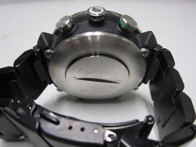
QITCD002
Mar 25, 2014Bluetooth Low Energy Smart Watch
Equipment Class
DTS - Digital Transmission System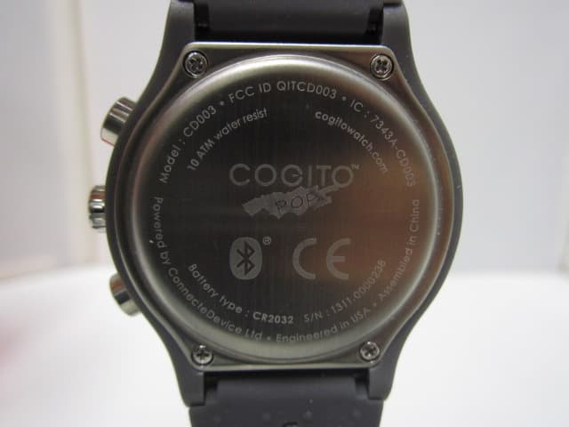
QITCD003
Feb 26, 2014Bluetooth Low Energy Smart Watch
Equipment Class
DTS - Digital Transmission System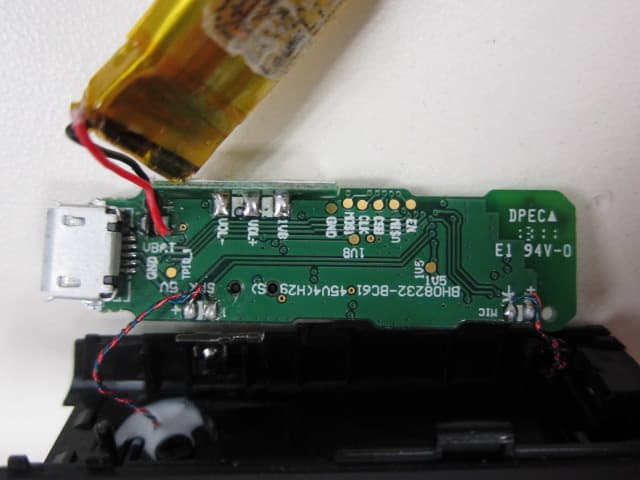
QITC45M
May 13, 2013Bluetooth Headset
Equipment Class
DSS - Part 15 Spread Spectrum Transmitter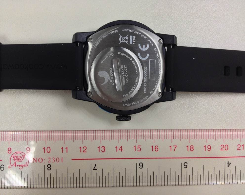
QITCOKO
Jan 08, 2013Bluetooth Low Energy Smart Watch
Equipment Class
DTS - Digital Transmission System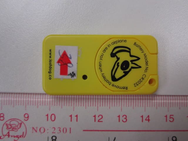
QIT2541
Oct 29, 2012BT Low Energy Device - LostDog smart keyfob
Equipment Class
DSS - Part 15 Spread Spectrum Transmitter