QITBTG2Bluetooth Headset
ConnecteDevice Limited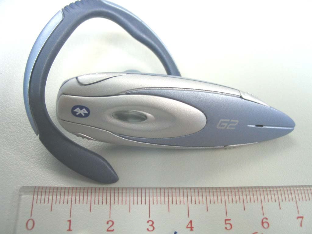
Click to zoom
Application Details
- Equipment Class
- DSS - Part 15 Spread Spectrum Transmitter
- Date of Grant
- Nov 30, 2003
- Application Purpose
- Original Equipment
- Date of Application
- Nov 30, 2003
- Equipment Note
- Bluetooth Headset
- Frequency Range
- 2402.00000000 - 2480.00000000
- Company
- ConnecteDevice Limited
- Country
- Hong Kong
Documents & Files
Document Text
Text extracted from the exhibit documents filed with the FCC. Open a document above to read the original.
Users Manual
PAGE 1 / 7 BlueTrek G2 user guide (page 1) IMPORTANT Before using your Bluetrek® G2 headset for the first time, you must charge it continuously for about 2 hours, until the blue indicator light turns on. Please refer to the “Charging Bluetrek® G2” section of this manual. FCC Statement This device complies with Part 15 of the FCC rules. Operation is subject to the following two conditions: (1) This device may not cause harmful interference, and (2) This device must accept any interference received, including interference that may cause undesired operation. Caution: Changes or modifications to this Bluetooth® headset not expressly approved by the Manufacturer could void the user’s authority to operate the equipment. Industry Canada notice to users and product statements To prevent radio interference to the licensed service, this device is intended to be operated indoors and away from windows to provide maximum shielding. Equipment (or its transmit antenna) that is installed outdoors is subject to licensing. Compliance to Industry Canada, technical specifications have been made in a declaration of conformity. It does not imply that Industry Canada approved the equipment. (page 2) (product picture) (page 3) 1. Introduction The Bluetrek G2 headset is a wireless headset based on the Bluetooth ® technology. The Bluetooth ® technology is a standard for wireless short distance radio communications. Devices like a headset and a mobile phone can communicate with each other without wires within approximately 10 meters. PAGE 2 / 7 Bluetrek® G2 is a qualified Bluetooth ® headset that complies with the Bluetooth ® 1.1 protocol. It supports two profiles: Headset Profiles and Hands-free profile. It will work with any qualified Bluetooth® device that supports the Headset profile or the Hands-free profile. To check the list of qualified Bluetooth® mobile phones working with Bluetrek® G2, please consult: www.bluetrek.com Bluetrek® G2 headset can be used with: - a qualified Bluetooth® mobile phone (*); - A non-Bluetooth® mobile phone (*) connected to the Bluetooth® adaptor BT07 (optional); (*) or another Bluetooth device supporting the Headset or Hands-free profile. This user guide is focusing on the use of this Bluetooth® headset with a Bluetooth® mobile phone, which is the most common application. Your Bluetrek® G2 will allow you to take a call, initiate a call (if your phone has voice controls), and adjust volume directly on your headset, without the need to touch your mobile phone. The Bluetrek® G2 headset has 5 buttons: • “TALK “Button (central button), • 2 “VOL+ “buttons, • 2 “VOL- “buttons. Please refer to the picture on page 2. Before using Bluetrek® G2 headset, you must: . Charge the headset; please refer to the “Charging Bluetrek® G2” section of this user guide. . Pair the headset with a mobile phone. Please refer to the “Pairing Bluetrek® G2” section of this manual. 1. Charging Bluetrek® G2 Your headset is delivered uncharged. So before the first use, you must fully recharge it for about 2 hours with the supplied charger, until the blue indicator light turns on. The use of any other charger will automatically suspend the warranty. During subsequent charges, the charging should take approximately 1 hour 45 minutes. Please connect the charger to the headset and to the mains. During the charge, the indicator light is either red if your headset battery was excessively discharged, or purple during a normal charge. The indicator light will turn to blue when the charge is complete. When you hear a light beep in your headset at regular intervals, and the indicator light flashes in red, your headset needs to be recharged. PAGE 3 / 7 To maximize battery lifetime, it is recommended to recharge your headset to full capacity only when the battery is low, since a battery has a lifetime of about 500 charging cycles. If you leave your headset battery empty for an extended period of time, it could excessively discharge the battery. In this case, you may have to charge your headset for 10 hours or more until the battery recovers and recharges completely. The indicator light will be red at the beginning of the charge to recover the battery capacity, then it will turn to purple for the normal charging process. Only switch on the headset once the blue indicator light turns on, indicating the battery has fully recovered. Do not let the battery charger plugged in the headset for more than 24h. 2. Pairing Bluetrek® G2 Before using the Bluetrek® G2 headset, you must pair it with your Bluetooth® mobile phone. Pairing is the process of linking 2 Bluetooth® devices, so that they can communicate. The pairing only needs to be done once. Afterwards, every time you switch on your headset, it will automatically connect to your mobile phone. If you pair your Bluetooth® mobile phone with another Bluetooth® device, you will have to pair the Bluetrek® G2 with your phone again before use. The profile (Headset or Hands-Free) is automatically selected by the Mobile phone during the Pairing stage. IMPORTANT : Before pairing, all Bluetooth® devices must be switched off. To initiate the pairing, put both the headset and the mobile phone within 0.3 meter (1 foot) from each other. Make sure there is no Wi-Fi equipment operating in the vicinity. 1. Switch on your phone and select the Bluetooth® discover mode on the Mobile phone (See the Bluetooth® mobile phone user guide). 2. Press and hold (do not release it) the TALK button (see button 1 on page 2) for about 7 seconds until the indicator light flashes red and blue alternatively. Then release the TALK Button. A beep can be heard in the speaker. 3.Once the mobile phone detects the headset, a message is displayed with the following information : “Bluetrek g2”. 4. Follow the phone instructions to accept the pairing. The PIN code (or passkey) is 0000. 5. When the pairing is completed, the indicator light will switch to blue, and flashes slowly. If you haven’t started the discovery mode within 5 …
Text truncated - open the document above for the full version.
Block Diagram
TÜV Rheinland Product Safety GmbH Am Grauen Stein D - 51105 Köln Appendix 4 Prüfbericht - Nr.: Test Report No. 14004841 001 Seite 3 von 6 Page 3 of 6 1.3 Block Diagram 1.3.1 Block Diagram of Bluetrek G2 Oscillator 16Mhz
External Photos
TÜV Rheinland Product Safety GmbH Am Grauen Stein D - 51105 Köln Appendix 3 Prüfbericht - Nr.: Test Report No. 14004841 001 Seite 1 von 4 Page 1 of 4 1.1 External view 1.1.1 Front view 1.1.2 Rear view TÜV Rheinland Product Safety GmbH Am Grauen Stein D - 51105 Köln Appendix 3 Prüfbericht - Nr.: Test Report No. 14004841 001 Seite 2 von 4 Page 2 of 4 1.1.3 Top view 1.1.4 Bottom view
ID Label/Location Info
TÜV Rheinland Product Safety GmbH Am Grauen Stein D - 51105 Köln Appendix 4 Prüfbericht - Nr.: Test Report No. 14004841 001 Seite 1 von 6 Page 1 of 6 1.1 FCCID Label Artwork
Internal Photos
TÜV Rheinland Product Safety GmbH Am Grauen Stein D - 51105 Köln Appendix 3 Prüfbericht - Nr.: Test Report No. 14004841 001 Seite 3 von 4 Page 3 of 4 1.2 Internal view 1.2.1 Front side 1 The yellow circle indicates the location of the antenna. TÜV Rheinland Product Safety GmbH Am Grauen Stein D - 51105 Köln Appendix 3 Prüfbericht - Nr.: Test Report No. 14004841 001 Seite 4 von 4 Page 4 of 4 1.2.2 Rear side 1 1.2.3 Rear side 2
Operational Description
TÜV Rheinland Product Safety GmbH Am Grauen Stein D - 51105 Köln Appendix 4 Prüfbericht - Nr.: Test Report No. 14004841 001 Seite 2 von 6 Page 2 of 6 1.2 Description of Circuit Function 1.2.1 General Description Bluetooth operates in the unlicensed ISM band at 2.4 GHz. A frequency hop transceiver is applied to combat interference and fading. A shaped, binary FM modulation is applied to minimize transceiver complexity. The symbol rate is 1 Ms/s. A slotted channel is applied with a nominal slot length of 625 μs. For full duplex transmission, a Time-Division Duplex (TDD) scheme is used. On the channel, information is exchanged through packets. Each packet is transmitted on a different hop frequency. A packet nominally covers a single slot, but can be extended to cover up to five slots. The Bluetooth protocol uses a combination of circuit and packet switching. Slots can be reserved for synchronous packets. Bluetooth can support an asynchronous data channel, up to three simultaneous synchronous voice channels, or a channel which simultaneously supports asynchronous data and synchronous voice. Each voice channel supports a 64 kb/s synchronous (voice) channel in each direction. The asynchronous channel can support maximal 723.2 kb/s asymmetric (and still up to 57.6 kb/s in the return direction), or 433.9 kb/s symmetric. The Bluetooth system consists of a radio unit, a link control unit, and a support unit for link management and host terminal interface functions.
Parts List/Tune Up Info
TÜV Rheinland Product Safety GmbH Am Grauen Stein D - 51105 Köln Appendix 4 Prüfbericht - Nr.: Test Report No. 14004841 001 Seite 5 von 6 Page 5 of 6 1.5 PCB Layout - Bottom silk TÜV Rheinland Product Safety GmbH Am Grauen Stein D - 51105 Köln Appendix 4 Prüfbericht - Nr.: Test Report No. 14004841 001 Seite 6 von 6 Page 6 of 6 - Top silk
Test Report
TÜV Rheinland Product Safety GmbH Am Grauen Stein D - 51105 Köln Prüfbericht - Nr.: Test Report No. 14004841 001 Seite 2 von 20 Page 2 of 20 1 Test Summary 7.1.1 ANTENNA CONNECTOR SUBCLAUSE 15.203 7.1.2 A NTENNA TYPE SUBCLAUSE 15.204 7.1.3 DISTURBANCE VOLTAGE ON AC MAINS SUBCLAUSE 15.207(A) RESULT: Pass Limit Subclause 15.207(a) 7.1.4 C ARRIER FREQUENCY SEPERATION SUBCLAUSE 15.247(A)(1) RESULT: Pass Limit Subclause 15.247(a)(1) 7.1.5 DWELL TIME SUBCLAUSE 15.247(A)(1)(III) RESULT: Pass Limit Subclause 15.247(a)(1)(iii) 7.1.6 20DB BANDWIDTH SUBCLAUSE 15.247(A)(1) 7.1.7 HOPPING SEQUENCE SUBCLAUSE 15.247(A)(1) 7.1.8 R ECEIVER INPUT BANDWIDTH SUBCLAUSE 15.247(A)(1) 7.1.9 PEAK OUTPUT POWER SUBCLAUSE 15.247(B)(1) RESULT: Pass Limit Subclause 15.247(b)(1) 7.1.10 BAND EDGE COMPLIANCE SUBCLAUSE 15.247(C) RESULT: Pass Limit Subclause 15.247(c) 7.1.11 SPURIOUS CONDUCTED EMISSIONS SUBCLAUSE 15.247(C) RESULT: Pass Limit Subclause 15.247(c) 7.1.12 SPURIOUS RADIATED EMISSIONS SUBCLAUSE 15.247(C) RESULT: Pass Limit Subclause 15.247(c) TÜV Rheinland Product Safety GmbH Am Grauen Stein D - 51105 Köln Prüfbericht - Nr.: Test Report No. 14004841 001 Seite 3 von 20 Page 3 of 20 2 Contents 1 TEST SUMMARY..................................................................................................................2 2 C ONTENTS...........................................................................................................................3 3 GENERAL REMARKS...........................................................................................................4 3.1 COMPLEMENTARY MATERIALS..........................................................................................4 4 TEST SITES..........................................................................................................................4 4.1 TEST FACILITIES.................................................................................................................4 4.2 L IST OF TEST AND MEASUREMENT INSTRUMENTS............................................................5 5 GENERAL PRODUCT INFORMATION...................................................................................6 5.1 PRODUCT FUNCTION AND INTENDED USE..........................................................................6 5.2 R ATINGS AND SYSTEM DETAILS.........................................................................................6 5.3 INDEPENDENT OPERATION MODES....................................................................................6 5.4 SUBMITTED DOCUMENTS....................................................................................................7 6 T EST SET-UP AND OPERATION MODE................................................................................7 6.1 P RINCIPLE OF CONFIGURATION SELECTION.....................................................................7 6.2 T EST OPERATION AND TEST SOFTWARE............................................................................7 6.3 S PECIAL ACCESSORIES AND AUXILIARY EQUIPMENT.......................................................7 7 T EST RESULTS.....................................................................................................................8 7.1.1 Antenna connector Subclause 15.203 ........................................................................................................ 8 7.1.2 Antenna type Subclause 15.204.................................................................................................................. 8 7.1.3 Disturbance voltage on AC mains Subclause 15.207(a) ............................................................................9 7.1.4 Carrier frequency seperation Subclause 15.247(a)(1).............................................................................11 7.1.5 Dwell time Subclause 15.247(a)(1)(iii) .................................................................................................... 12 7.1.6 20dB bandwidth Subclause 15.247(a)(1) ................................................................................................. 13 7.1.7 Hopping sequence Subclause 15.247(a)(1).............................................................................................. 14 7.1.8 Receiver input bandwidth Subclause 15.247(a)(1) .................................................................................. 15 7.1.9 Peak output power Subclause 15.247(b)(1) ............................................................................................. 16 7.1.10 Band edge compliance Subclause 15.247(c) .......................................................................................17 7.1.11 Spurious conducted emissions Subclause 15.247(c) ........................................................................... 18 7.1.12 Spurious radiated emissions Subclause 15.247(c) .............................................................................. 19 TÜV Rheinland Product Safety GmbH Am Grauen Stein D - 51105 Köln Prüfbericht - Nr.: Test Report No. 14004841 001 Seite 4 von 20 Page 4 of 20 3 General Remarks 3.1 Complementary Materials All attachments are integral parts of this test report. This applies especially to the following appendix: Appendix 1: Test Results Appendix 2: Test Setup Appendix 3: EUT Photos Appendix 4: FCCID Label, Block Diagram and Schematics 4 Test Sites 4.1 Test Facilities Hong Kong Productivity Council HKPC Building 78 Tat Chee Avenue Kowloon Hong Kong TÜV Rheinland Product Safety GmbH Am Grauen Stein D - 51105 Köln Prüfbericht - Nr.: Test Report No. 14004841 001 Seite 5 von 20 Page 5 of 20 4.2 List of Test and Measurement Instruments Table 1: List of Test and Measurement Equipment Kind of Equipment Manufacturer Type S/N Test Receiver Rohde & Schwarz ESHS30 847115/005 L/I/S/N Rohde & Schwarz ESH 3-Z5 849876/026 Oscilloscope HP 54713B US34510455 Test Receiver Rohde & Schwarz ESVP 882402/033 Absorbing Clamp Rohde & Schwarz MDS-21 979 3/4 Test Receiver Rohde & S…
Text truncated - open the document above for the full version.
Test Setup Photos
TÜV Rheinland Product Safety GmbH Am Grauen Stein D - 51105 Köln Appendix 2 Prüfbericht - Nr.: Test Report No. 14004841 001 Seite 1 von 3 Page 1 of 3 1.1 Test set-up 1.1.1 Spurious Radiated Emissions TÜV Rheinland Product Safety GmbH Am Grauen Stein D - 51105 Köln Appendix 2 Prüfbericht - Nr.: Test Report No. 14004841 001 Seite 2 von 3 Page 2 of 3 TÜV Rheinland Product Safety GmbH Am Grauen Stein D - 51105 Köln Appendix 2 Prüfbericht - Nr.: Test Report No. 14004841 001 Seite 3 von 3 Page 3 of 3 1.1.2 Disturbance voltage on AC mains
Contact Information
Applicant
Henri-Nicolas Olivier(CEO)
Technical Contact
T�V Rheinland Hong Kong Ltd.Stephan Wald
[email protected]+852 2192 1000
Room 405, Tech Centre · Hong Kong · Hong Kong
Non-Technical Contact
Innovi Technologies Ltd.Guillaume Ponticelli
[email protected]+852 2915 6139
Test Firm
Hong Kong Productivity CouncilIr Angel Wong Yuen-yee
Technical Specifications
| # | Rule Parts | Frequency Range | Power Output |
|---|---|---|---|
| 1 | 15C | 2.40 GHz - 2.48 GHz | 1.48 mW |
Other Applications from ConnecteDevice Limited
QITCD002
Mar 25, 2014Bluetooth Low Energy Smart Watch
Equipment Class
DTS - Digital Transmission System
QITCD003
Feb 26, 2014Bluetooth Low Energy Smart Watch
Equipment Class
DTS - Digital Transmission System
QITC45M
May 13, 2013Bluetooth Headset
Equipment Class
DSS - Part 15 Spread Spectrum Transmitter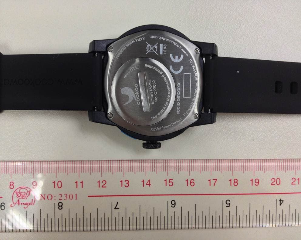
QITCOKO
Jan 08, 2013Bluetooth Low Energy Smart Watch
Equipment Class
DTS - Digital Transmission System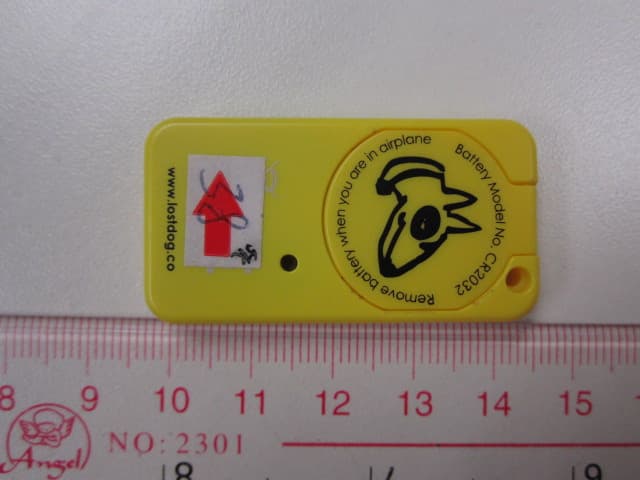
QIT2541
Oct 29, 2012BT Low Energy Device - LostDog smart keyfob
Equipment Class
DSS - Part 15 Spread Spectrum Transmitter