QIU-CXP-MVA-GNRGateway
Corinex Communication Corp.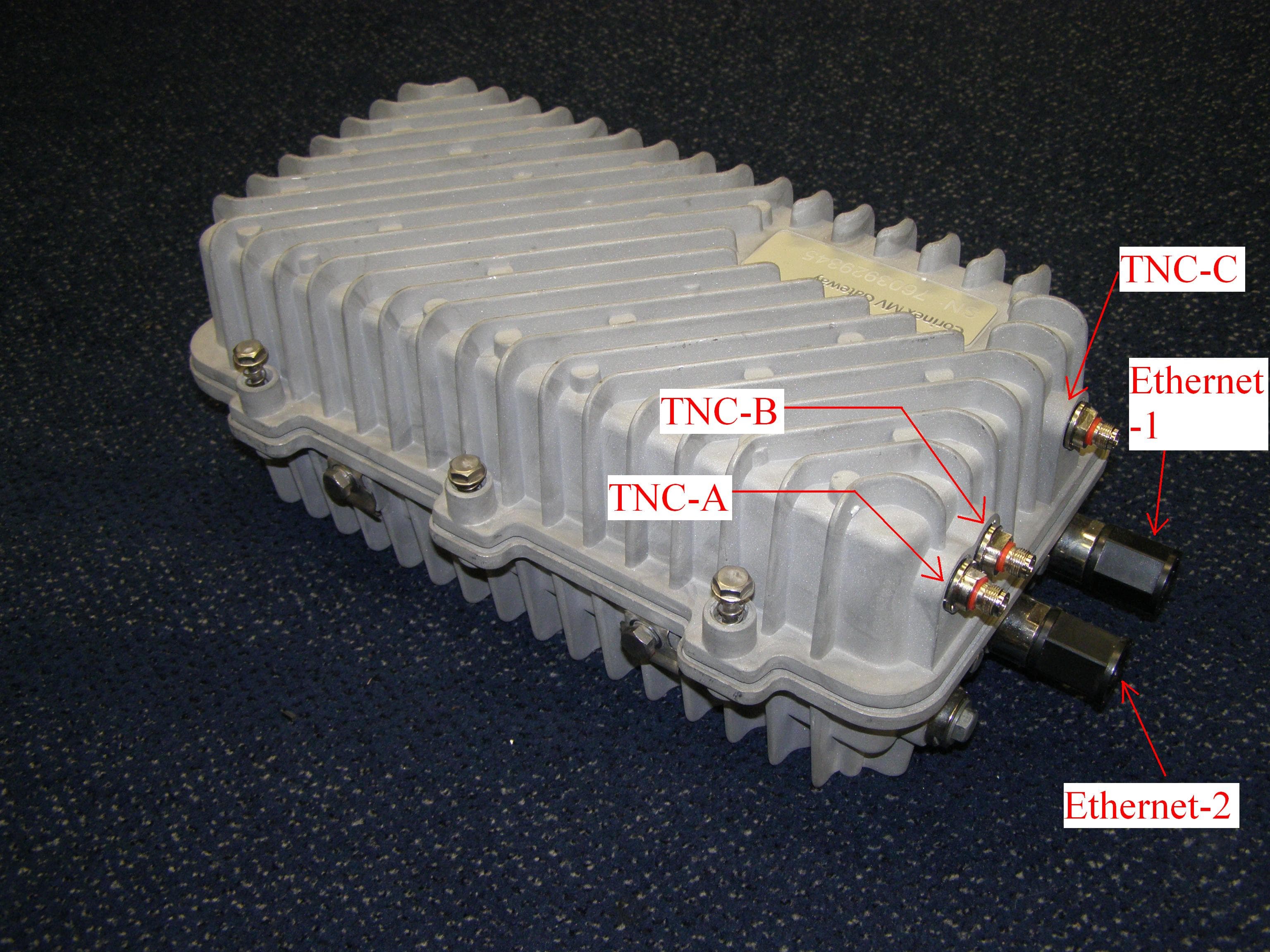
Click to zoom
Application Details
- Equipment Class
- BPL - Access Broadband Over Powerline System
- Date of Grant
- Mar 04, 2008
- Application Purpose
- Original Equipment
- Date of Application
- Dec 19, 2007
- Equipment Note
- Gateway
- Frequency Range
- 2.00000000 - 32.00000000
- Company
- Corinex Communication Corp.
- Country
- Canada
Documents & Files
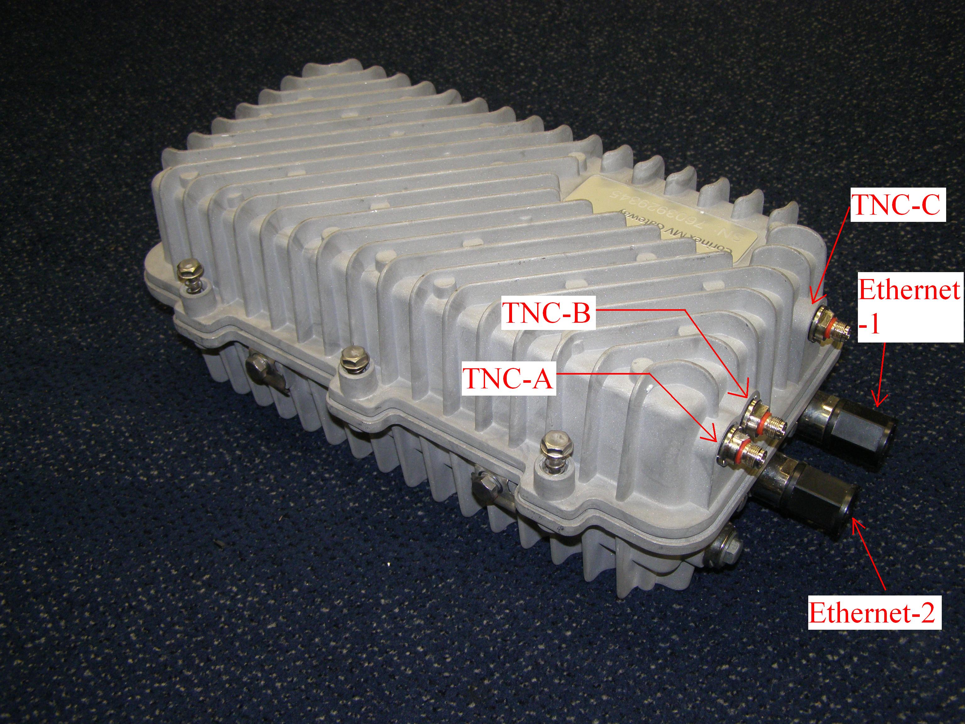
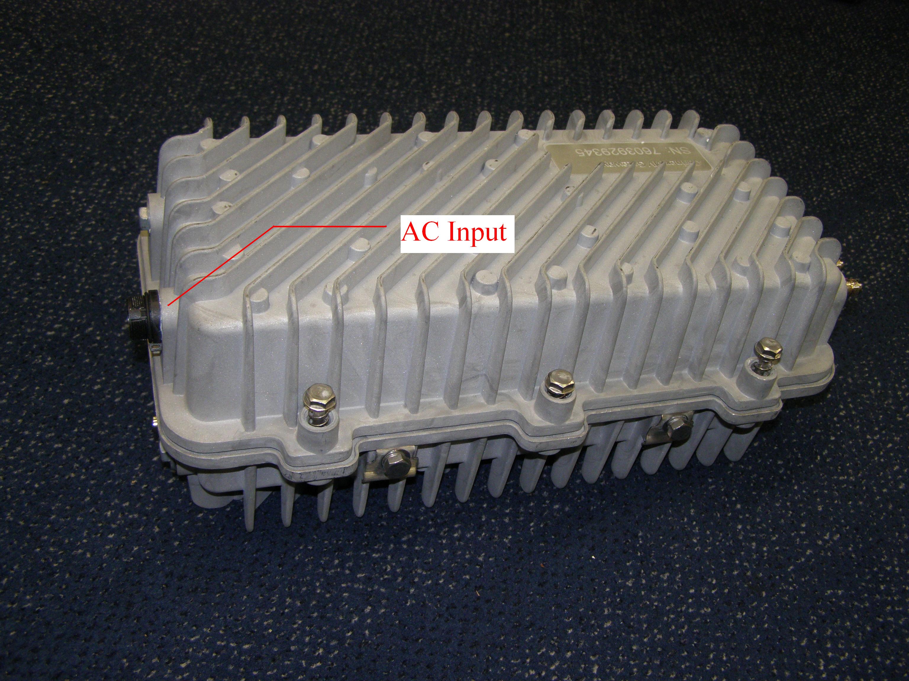
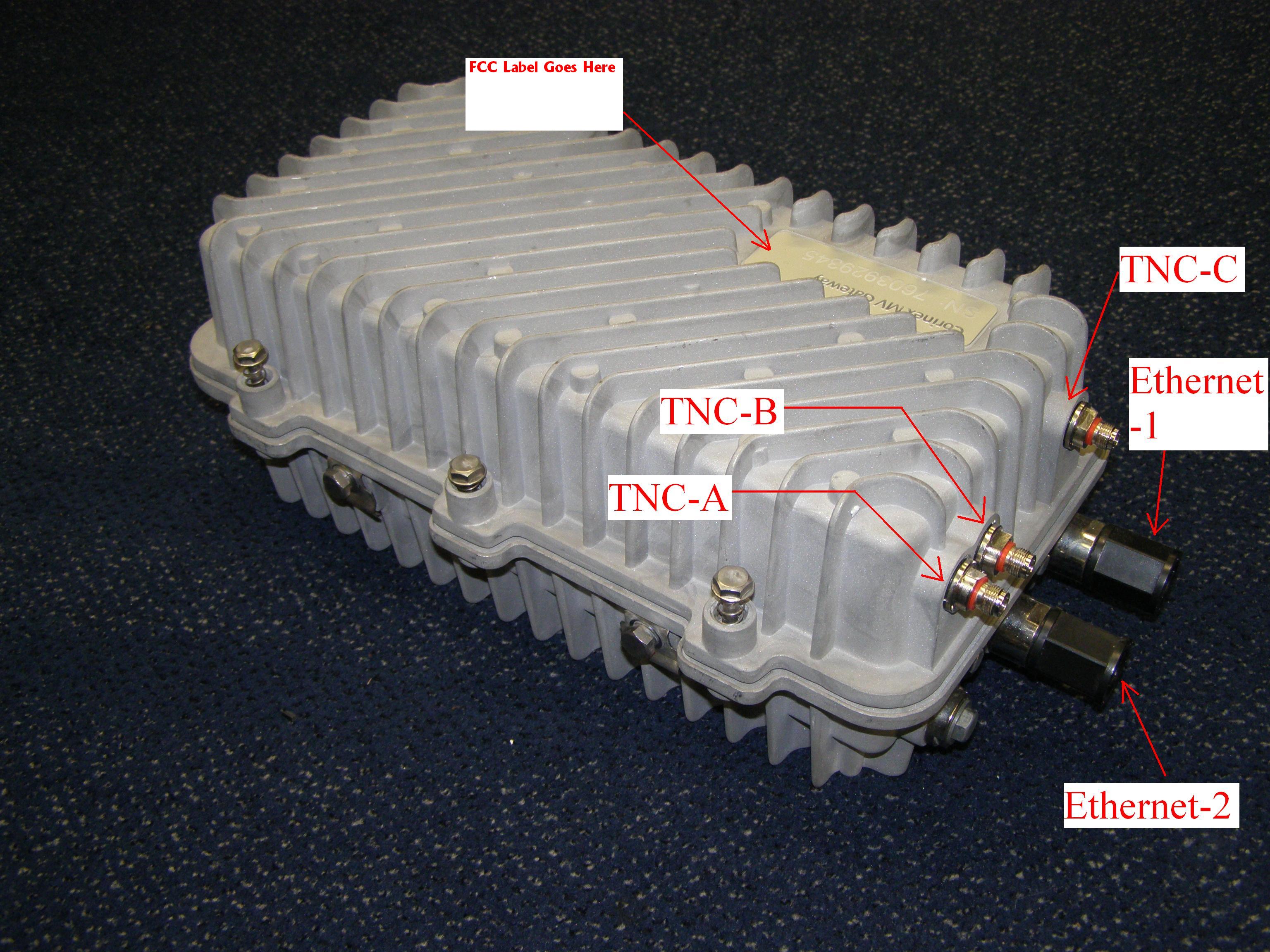
Document Text
Text extracted from the exhibit documents filed with the FCC. Open a document above to read the original.
Attestation Statements
Corinex Communications Corp. 601 – 905 W. Pender Street Vancouver, BC V6C 1L6 Canada 604 692 0520 www.corinex.com 20 November 2007 To whom it may concern: We the undersigned, hereby authorize Professional Testing (EMI), Inc. to act on our behalf in all manners relating to application for equipment authorization, including signing of all documents relating to these matters. Any and all acts carried out by Professional Testing (EMI), Inc., on our behalf shall have the same affect as acts of our own with the sole exception of any potential matters requiring extra fees beyond the normal filing fee for the product to be certified. This authorization is valid until December 31, 2007 from Corinex Communications Corp. Sincerely, Brian Donnelly VP, Marketing and Business Development
Cover Letter(s)
To: Federal Communications Commission Re: Confidentiality of exibits FCC ID: UIU-CXP-MVA-GNR From: Professional Testing, Mike Royer Dear Sir or Madam, Please hold Block Diagrams and internal photographs for the product application reference above in confidence. Disclosing this information publicly would be a disadvantage to Corinex Communications. Sincerely, Mike Royer, Professional Testing
ID Label/Location Info
This device complies with Part 15 of the FCC Rules. Operation is subject to the following two conditions: (1) this device may not cause harmful interference, and (2) this device must accept any interference received, including interference that may cause undesired operation. FCC ID: QIU-CXP-MVA-GNR Serial Number
Test Report
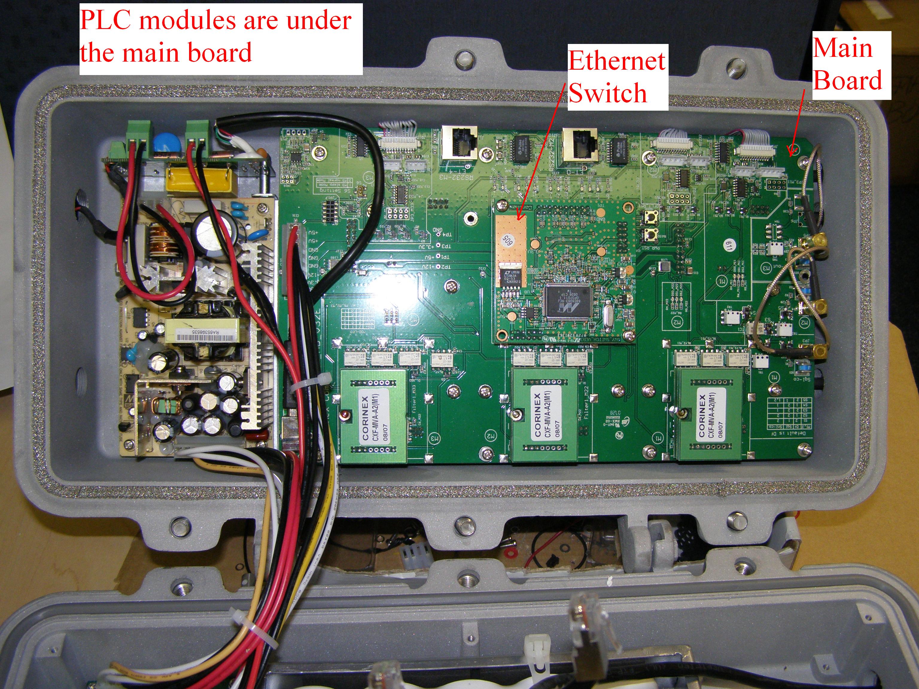
Buried Site 1 Low Voltage Professional Testing 12/20/2007 1 Broadband over Power Lines (BPL) FCC Emissions Compliance Guidelines Access-Underground Emissions testing to FCC Report & Order 04-245 (FCC Method) Access-Underground BPL component being tested: Repeater Applicable Standards for this test: STANDARD TITLE ANSI C63.4 - 2003 American National Standard for Methods of Measurement of Radio-Noise Emissions from Low-Voltage Electrical and Electronic Equipment in the Range of 9 kHz to 40 GHz EUT CONFIGURATION Product Type BPL medium voltage (MV) Access Gateway Serial Number 7353125931/6401625558/6938020727/6284826266 Model Number CXP-MVA-GWY (T3B) Marketing Designation Corinex NR – MV Gateway Chassis Revision Number MV-Gateway V1 Firmware Revision Number ac_CXP_GNR_GWY_A2_hv1_0_0_sv3_4_8_2_0_0 ECO Number (if applicable) ID # QIU-CXP-MVA-GNR EUT OPERATING PARAMETERS Modulation type OFDM Number of carriers 1536 Carrier spacing Medium Voltage, mode 1, Spacing 6.51 kHz Medium Voltage, mode 2, Spacing 4.56 kHz Medium Voltage, mode 3, Spacing 6.51 kHz Low Voltage, Spacing 18.23 kHz Channel bandwidth Mode 1:10MHz; Mode 2 :7MHz; Mode 3 :10MHz Lowest external frequency used 3MHz Highest external frequency used 32MHz Notching depth capability (dB) 30dB by default; 40dB maximum Carrier On-Off remotely? (yes/no) Yes Power Setting mechanism Default is power setting mask and notches active. Maximum power setting 50mW/mode, 150mW total. Range of duty factors (rep rates) 95% Highest internal frequency Crystal: 80MHz Description of operation The Corinex MV Access Gateway has 3 Powerline modules, an Ethernet switch between the modules, a power supply, and an industrial case that acts as a heat sink to the environment. The Gateway is attached to a utility pole via a bracket, typically located 20’ or higher on the pole. Two of the 3 outputs of the device used for Medium Voltage communications with one being used for Low Voltage Communications. The MV outputs are connected to an MV Capacitive and Inductive Coupler and then attached to the MV line, the connector on the MV Gateway is an TNC type coaxial connector. The 2 MV outputs allow for connection to additional MV Gateway devices either “before” or “after” the device. The power cord for the device is also used for signal transmission on the Low Voltage lines and is internally coupled. The Ethernet switch within the device allows for inter-module communications. Finally, a grounding lug is Buried Site 1 Low Voltage Professional Testing 12/20/2007 2 provided on the device that is attached to the grounding wire on the pole. The MV Access Gateway uses orthogonal frequency-division multiplexing for modulation, which is a complex modulation technique for transmission based upon the idea of frequency-division multiplexing (FDM) where each frequency channel is modulated with a simpler modulation. We use 1536 carriers in our transmission. In each transmission, its normal operation mode will result in 20- 25 pulse per second. Signaling type used is RF signals transmitted on MV powerlines with a frequency of 3-32 MHz. Unlike some MV Access devices, Corinex only uses Frequency Division Duplexing to communicate. The device is IP based and as such any IP packet can be transmitted over the network. Typical applications of the device include broadband internet access and the transmission of utility asset information. Rationale for selection of test site: This site was chosen as one of three representative installations for this component because the area was free of obstructions, and had low ambient. OBJECT This test procedure outlines the specific electromagnetic compatibility (EMC) emissions testing requirements applicable to Access BPL Underground installations. This procedure will be used for the testing and comparison of results from various locations and system architectures. EUT PASS CRITERIA Location Test Frequency Range Limits 9 kHz – 30 MHz 29.5 dB(μV/m) measured at 30 meters 1 30 MHz - 88 MHz 39.1 dB(μV/m) measured at 10 meters 1 88 MHz – 216 MHz 43.5 dB(μV/m) measured at 10 meters 1 216 MHz – 960 MHz 56.4 dB(μV/m) measured at 10 meters 1 “In situ” Radiated Emissions Above 960 MHz 49.5 dB(μV/m) measured at 10 meters 1 Note 1: Installations will be measured at slant-range distances other than those listed above. The formulas to find the dB value to subtract from the measured values when data are taken at distances other than those indicated are: 40log 10 30m/d n for frequencies below 30MHz 20log 10 10m/d n for frequencies above 30MHz RADIATED EMISSIONS LIMITS (above 30 MHz) Buried Site 1 Low Voltage Professional Testing 12/20/2007 3 FCC Radiated Emissions Limits for CLASS A Equipment 30 32 34 36 38 40 42 44 46 48 50 101001000 FREQUENCY (MHz) EMI S S I O N L I MI T ( d Bμ V/ m ) dBμV/m @ 10 m Unintentional Radiator Upper Frequency Range of Measurement Highest frequency used in the device (MHz) Upper Frequency of Measurement (MHz) 1.705-108MHz 1,000MHz 108-500MHz 2,000MHz 500-1,000MHz 5,000MHz Above 1,000MHz 5 th Harmonic <40GHz The upper frequency of measurement for this test is 1000 MHz. Antennas are specific to the frequency range being measured, and are summarized in this table. Typical antennas for BPL Certification testing Frequency Range Antenna 9kHz-30MHz Active Loop (corrected to E-field by adding 51.2dB) 30-1000MHz Bilog Enter the correct equipment information into the Equipment List. (Samples are shown below, replace with actual data) EQUIPMENT LIST Buried Site 1 Low Voltage Professional Testing 12/20/2007 4 Manufacturer Description Model Number Serial Number Asset number Cal Due PTI 1.9 MHz High Pass Filter 1182 15 Aug. 2008 Hewlett Packard EMC Spectrum Analyzer 8591EM 3322A09711 0410 7 Dec. 2007 Hewlett Packard Preamplifier 8447A 2439A09711 1260 9 April 2008 Miteq Preamplifier 4888 1453 1 May 2008 Tektronix Preselector 2706 B010106 0746 29 Nov. 07 ETS Passive loop antenna 6512 Prototype 0351 22 Dec. 2007 AH Systems Bilog Antenna SAS-521-2 2662436 15 A…
Text truncated - open the document above for the full version.
Test Report
Buried Site 1 Medium Voltage Professional Testing 12/20/2007 1 Broadband over Power Lines (BPL) FCC Emissions Compliance Guidelines Access-Underground Emissions testing to FCC Report & Order 04-245 (FCC Method) Indicate type of Access-Underground BPL component being tested, such as injector, repeater, extractor, etc. Access-Underground BPL component being tested: Repeater Applicable Standards for this test: STANDARD TITLE ANSI C63.4 - 2003 American National Standard for Methods of Measurement of Radio-Noise Emissions from Low-Voltage Electrical and Electronic Equipment in the Range of 9 kHz to 40 GHz EUT CONFIGURATION Product Type BPL medium voltage (MV) Access Gateway Serial Number 7353125931/6401625558/6938020727/6284826266 Model Number CXP-MVA-GWY (T3B) Marketing Designation Corinex NR – MV Gateway Chassis Revision Number MV-Gateway V1 Firmware Revision Number ac_CXP_GNR_GWY_A2_hv1_0_0_sv3_4_8_2_0_0 ECO Number (if applicable) ID # QIU-CXP-MVA-GNR EUT OPERATING PARAMETERS Modulation type OFDM Number of carriers 1536 Carrier spacing Medium Voltage, mode 1, Spacing 6.51 kHz Medium Voltage, mode 2, Spacing 4.56 kHz Medium Voltage, mode 3, Spacing 6.51 kHz Low Voltage, Spacing 18.23 kHz Channel bandwidth Mode 1:10MHz; Mode 2 :7MHz; Mode 3 :10MHz Lowest external frequency used 3MHz Highest external frequency used 32MHz Notching depth capability (dB) 30dB by default; 40dB maximum Carrier On-Off remotely? (yes/no) Yes Power Setting mechanism Default is power setting mask and notches active. Maximum power setting 50mW/mode, 150mW total. Range of duty factors (rep rates) 95% Highest internal frequency Crystal: 80MHz Description of operation The Corinex MV Access Gateway has 3 Powerline modules, an Ethernet switch between the modules, a power supply, and an industrial case that acts as a heat sink to the environment. The Gateway is attached to a utility pole via a bracket, typically located 20’ or higher on the pole. Two of the 3 outputs of the device used for Medium Voltage communications with one being used for Low Voltage Communications. The MV outputs are connected to an MV Capacitive and Inductive Coupler and then attached to the MV line, the connector on the MV Gateway is an TNC type coaxial connector. The 2 MV outputs allow for connection to additional MV Gateway devices either “before” or “after” the device. The power cord for the device is also used for signal transmission on the Low Voltage lines and is internally coupled. The Ethernet switch within the Buried Site 1 Medium Voltage Professional Testing 12/20/2007 2 device allows for inter-module communications. Finally, a grounding lug is provided on the device that is attached to the grounding wire on the pole. The MV Access Gateway uses orthogonal frequency-division multiplexing for modulation, which is a complex modulation technique for transmission based upon the idea of frequency-division multiplexing (FDM) where each frequency channel is modulated with a simpler modulation. We use 1536 carriers in our transmission. In each transmission, its normal operation mode will result in 20- 25 pulse per second. Signaling type used is RF signals transmitted on MV powerlines with a frequency of 3-32 MHz. Unlike some MV Access devices, Corinex only uses Frequency Division Duplexing to communicate. The device is IP based and as such any IP packet can be transmitted over the network. Typical applications of the device include broadband internet access and the transmission of utility asset information. Rationale for selection of test site: This site was chosen as one of three representative installations for this component because the area was free of obstructions and had low ambient. OBJECT This test procedure outlines the specific electromagnetic compatibility (EMC) emissions testing requirements applicable to Access BPL Underground installations. This procedure will be used for the testing and comparison of results from various locations and system architectures. EUT PASS CRITERIA Location Test Frequency Range Limits 9 kHz – 30 MHz 29.5 dB(μV/m) measured at 30 meters 1 30 MHz - 88 MHz 39.1 dB(μV/m) measured at 10 meters 1 88 MHz – 216 MHz 43.5 dB(μV/m) measured at 10 meters 1 216 MHz – 960 MHz 56.4 dB(μV/m) measured at 10 meters 1 “In situ” Radiated Emissions Above 960 MHz 49.5 dB(μV/m) measured at 10 meters 1 Note 1: Installations will be measured at slant-range distances other than those listed above. The formulas to find the dB value to subtract from the measured values when data are taken at distances other than those indicated are: 40log 10 30m/d n for frequencies below 30MHz 20log 10 10m/d n for frequencies above 30MHz RADIATED EMISSIONS LIMITS (above 30 MHz) Buried Site 1 Medium Voltage Professional Testing 12/20/2007 3 FCC Radiated Emissions Limits for CLASS A Equipment 30 32 34 36 38 40 42 44 46 48 50 101001000 FREQUENCY (MHz) E M IS S I ON LIM I T (dBμ V / m) dBμV/m @ 10 m Unintentional Radiator Upper Frequency Range of Measurement Highest frequency used in the device (MHz) Upper Frequency of Measurement (MHz) 1.705-108MHz 1,000MHz 108-500MHz 2,000MHz 500-1,000MHz 5,000MHz Above 1,000MHz 5 th Harmonic <40GHz The upper frequency of measurement for this test is 1000 MHz. Antennas are specific to the frequency range being measured, and are summarized in this table. Typical antennas for BPL Certification testing Frequency Range Antenna 9kHz-30MHz Active Loop (corrected to E-field by adding 51.2dB) 30-1000MHz Bilog Enter the correct equipment information into the Equipment List. (Samples are shown below, replace with actual data) EQUIPMENT LIST Buried Site 1 Medium Voltage Professional Testing 12/20/2007 4 Manufacturer Description Model Number Serial Number Asset Number Cal Due PTI 1.9 MHz High Pass Filter 1182 15 Aug. 2008 Hewlett Packard EMC Spectrum Analyzer 8591EM 3322A09711 0410 7 Dec. 2007 Hewlett Packard Preamplifier 8447A 2439A09711 1260 9 April 2008 Miteq Preamplifier 4888 1453 1 May 2008 Tektronix Preselector 2706 B010106 0746 …
Text truncated - open the document above for the full version.
Test Report
Buried Site 2 Low Voltage Professional Testing 12/20/2007 1 Broadband over Power Lines (BPL) FCC Emissions Compliance Guidelines Access-Underground Emissions testing to FCC Report & Order 04-245 (FCC Method) Access-Underground BPL component being tested: Repeater Applicable Standards for this test: STANDARD TITLE ANSI C63.4 - 2003 American National Standard for Methods of Measurement of Radio-Noise Emissions from Low-Voltage Electrical and Electronic Equipment in the Range of 9 kHz to 40 GHz EUT CONFIGURATION Product Type BPL medium voltage (MV) Access Gateway Serial Number 7353125931/6401625558/6938020727/6284826266 Model Number CXP-MVA-GWY (T3B) Marketing Designation Corinex NR – MV Gateway Chassis Revision Number MV-Gateway V1 Firmware Revision Number ac_CXP_GNR_GWY_A2_hv1_0_0_sv3_4_8_2_0_0 ECO Number (if applicable) ID # QIU-CXP-MVA-GNR EUT OPERATING PARAMETERS Modulation type OFDM Number of carriers 1536 Carrier spacing Medium Voltage, mode 1, Spacing 6.51 kHz Medium Voltage, mode 2, Spacing 4.56 kHz Medium Voltage, mode 3, Spacing 6.51 kHz Low Voltage, Spacing 18.23 kHz Channel bandwidth Mode 1:10MHz; Mode 2 :7MHz; Mode 3 :10MHz Lowest external frequency used 3MHz Highest external frequency used 32MHz Notching depth capability (dB) 30dB by default; 40dB maximum Carrier On-Off remotely? (yes/no) Yes Power Setting mechanism Default is power setting mask and notches active. Maximum power setting 50mW/mode, 150mW total. Range of duty factors (rep rates) 95% Highest internal frequency Crystal: 80MHz Description of operation The Corinex MV Access Gateway has 3 Powerline modules, an Ethernet switch between the modules, a power supply, and an industrial case that acts as a heat sink to the environment. The Gateway is attached to a utility pole via a bracket, typically located 20’ or higher on the pole. Two of the 3 outputs of the device used for Medium Voltage communications with one being used for Low Voltage Communications. The MV outputs are connected to an MV Capacitive and Inductive Coupler and then attached to the MV line, the connector on the MV Gateway is an TNC type coaxial connector. The 2 MV outputs allow for connection to additional MV Gateway devices either “before” or “after” the device. The power cord for the device is also used for signal transmission on the Low Voltage lines and is internally coupled. The Ethernet switch within the device allows for inter-module communications. Finally, a grounding lug is Buried Site 2 Low Voltage Professional Testing 12/20/2007 2 provided on the device that is attached to the grounding wire on the pole. The MV Access Gateway uses orthogonal frequency-division multiplexing for modulation, which is a complex modulation technique for transmission based upon the idea of frequency-division multiplexing (FDM) where each frequency channel is modulated with a simpler modulation. We use 1536 carriers in our transmission. In each transmission, its normal operation mode will result in 20- 25 pulse per second. Signaling type used is RF signals transmitted on MV powerlines with a frequency of 3-32 MHz. Unlike some MV Access devices, Corinex only uses Frequency Division Duplexing to communicate. The device is IP based and as such any IP packet can be transmitted over the network. Typical applications of the device include broadband internet access and the transmission of utility asset information. Rationale for selection of test site: This site was chosen as one of three representative installations for this component because it is free of obstructions and has a low ambient. OBJECT This test procedure outlines the specific electromagnetic compatibility (EMC) emissions testing requirements applicable to Access BPL Underground installations. This procedure will be used for the testing and comparison of results from various locations and system architectures. EUT PASS CRITERIA Location Test Frequency Range Limits 9 kHz – 30 MHz 29.5 dB(μV/m) measured at 30 meters 1 30 MHz - 88 MHz 39.1 dB(μV/m) measured at 10 meters 1 88 MHz – 216 MHz 43.5 dB(μV/m) measured at 10 meters 1 216 MHz – 960 MHz 56.4 dB(μV/m) measured at 10 meters 1 “In situ” Radiated Emissions Above 960 MHz 49.5 dB(μV/m) measured at 10 meters 1 Note 1: Installations will be measured at slant-range distances other than those listed above. The formulas to find the dB value to subtract from the measured values when data are taken at distances other than those indicated are: 40log 10 30m/d n for frequencies below 30MHz 20log 10 10m/d n for frequencies above 30MHz RADIATED EMISSIONS LIMITS (above 30 MHz) Buried Site 2 Low Voltage Professional Testing 12/20/2007 3 FCC Radiated Emissions Limits for CLASS A Equipment 30 32 34 36 38 40 42 44 46 48 50 101001000 FREQUENCY (MHz) E M IS S I ON LIM I T (dBμ V / m) dBμV/m @ 10 m Unintentional Radiator Upper Frequency Range of Measurement Highest frequency used in the device (MHz) Upper Frequency of Measurement (MHz) 1.705-108MHz 1,000MHz 108-500MHz 2,000MHz 500-1,000MHz 5,000MHz Above 1,000MHz 5 th Harmonic <40GHz The upper frequency of measurement for this test is 1000 MHz. Typical antennas for BPL Certification testing Frequency Range Antenna 9kHz-30MHz Active Loop (corrected to E-field by adding 51.2dB) 30-1000MHz Bilog EQUIPMENT LIST Buried Site 2 Low Voltage Professional Testing 12/20/2007 4 Manufacturer Description Model Number Serial Number Cal Due PTI 1.9 MHz High Pass Filter 1182 15 Aug. 2008 Hewlett Packard EMC Spectrum Analyzer 8591EM 3322A09711 0410 7 Dec. 2007 Hewlett Packard Preamplifier 8447A 2439A09711 1260 9 April 2008 Miteq Preamplifier 4888 1453 1 May 2008 Tektronix Preselector 2706 B010106 0746 29 Nov. 07 ETS Passive loop antenna 6512 Prototype 0351 22 Dec. 2007 AH Systems Bilog Antenna SAS-521-2 2662436 15 Aug. 2008 ETS Non-metallic tripod 4-TR N/A 0944 N/A Pasternak RG-214, 150 ft. 28 Oct. 2008 Lufkin Tape measure 30’ N/A N/A SUPPORTING EQUIPMENT DOCUMENTATION CHECKLIST 9 Preamplifier gain VS frequency curve Attached to test report 9 Ty…
Text truncated - open the document above for the full version.
Test Report
Buried Site 2 Medium Voltage Professional Testing 12/20/2007 1 Broadband over Power Lines (BPL) FCC Emissions Compliance Guidelines Access-Underground Emissions testing to FCC Report & Order 04-245 (FCC Method) Access-Underground BPL component being tested: Repeater Applicable Standards for this test: STANDARD TITLE ANSI C63.4 - 2003 American National Standard for Methods of Measurement of Radio-Noise Emissions from Low-Voltage Electrical and Electronic Equipment in the Range of 9 kHz to 40 GHz EUT CONFIGURATION Product Type BPL medium voltage (MV) Access Gateway Serial Number 7353125931/6401625558/6938020727/6284826266 Model Number CXP-MVA-GWY (T3B) Marketing Designation Corinex NR – MV Gateway Chassis Revision Number MV-Gateway V1 Firmware Revision Number ac_CXP_GNR_GWY_A2_hv1_0_0_sv3_4_8_2_0_0 ECO Number (if applicable) ID # QIU-CXP-MVA-GNR EUT OPERATING PARAMETERS Modulation type OFDM Number of carriers 1536 Carrier spacing Medium Voltage, mode 1, Spacing 6.51 kHz Medium Voltage, mode 2, Spacing 4.56 kHz Medium Voltage, mode 3, Spacing 6.51 kHz Low Voltage, Spacing 18.23 kHz Channel bandwidth Mode 1:10MHz; Mode 2 :7MHz; Mode 3 :10MHz Lowest external frequency used 3MHz Highest external frequency used 32MHz Notching depth capability (dB) 30dB by default; 40dB maximum Carrier On-Off remotely? (yes/no) Yes Power Setting mechanism Default is power setting mask and notches active. Maximum power setting 50mW/mode, 150mW total. Range of duty factors (rep rates) 95% Highest internal frequency Crystal: 80MHz Description of operation The Corinex MV Access Gateway has 3 Powerline modules, an Ethernet switch between the modules, a power supply, and an industrial case that acts as a heat sink to the environment. The Gateway is attached to a utility pole via a bracket, typically located 20’ or higher on the pole. Two of the 3 outputs of the device used for Medium Voltage communications with one being used for Low Voltage Communications. The MV outputs are connected to an MV Capacitive and Inductive Coupler and then attached to the MV line, the connector on the MV Gateway is an TNC type coaxial connector. The 2 MV outputs allow for connection to additional MV Gateway devices either “before” or “after” the device. The power cord for the device is also used for signal transmission on the Low Voltage lines and is internally coupled. The Ethernet switch within the device allows for inter-module communications. Finally, a grounding lug is Buried Site 2 Medium Voltage Professional Testing 12/20/2007 2 provided on the device that is attached to the grounding wire on the pole. The MV Access Gateway uses orthogonal frequency-division multiplexing for modulation, which is a complex modulation technique for transmission based upon the idea of frequency-division multiplexing (FDM) where each frequency channel is modulated with a simpler modulation. We use 1536 carriers in our transmission. In each transmission, its normal operation mode will result in 20- 25 pulse per second. Signaling type used is RF signals transmitted on MV powerlines with a frequency of 3-32 MHz. Unlike some MV Access devices, Corinex only uses Frequency Division Duplexing to communicate. The device is IP based and as such any IP packet can be transmitted over the network. Typical applications of the device include broadband internet access and the transmission of utility asset information. Rationale for selection of test site: This site was chosen as one of three representative installations for this component because it is free of obstructions and has a low ambient. OBJECT This test procedure outlines the specific electromagnetic compatibility (EMC) emissions testing requirements applicable to Access BPL Underground installations. This procedure will be used for the testing and comparison of results from various locations and system architectures. EUT PASS CRITERIA Location Test Frequency Range Limits 9 kHz – 30 MHz 29.5 dB(μV/m) measured at 30 meters 1 30 MHz - 88 MHz 39.1 dB(μV/m) measured at 10 meters 1 88 MHz – 216 MHz 43.5 dB(μV/m) measured at 10 meters 1 216 MHz – 960 MHz 56.4 dB(μV/m) measured at 10 meters 1 “In situ” Radiated Emissions Above 960 MHz 49.5 dB(μV/m) measured at 10 meters 1 Note 1: Installations will be measured at slant-range distances other than those listed above. The formulas to find the dB value to subtract from the measured values when data are taken at distances other than those indicated are: 40log 10 30m/d n for frequencies below 30MHz 20log 10 10m/d n for frequencies above 30MHz RADIATED EMISSIONS LIMITS (above 30 MHz) Buried Site 2 Medium Voltage Professional Testing 12/20/2007 3 FCC Radiated Emissions Limits for CLASS A Equipment 30 32 34 36 38 40 42 44 46 48 50 101001000 FREQUENCY (MHz) E M IS S I ON LIM I T (dBμ V / m) dBμV/m @ 10 m Unintentional Radiator Upper Frequency Range of Measurement Highest frequency used in the device (MHz) Upper Frequency of Measurement (MHz) 1.705-108MHz 1,000MHz 108-500MHz 2,000MHz 500-1,000MHz 5,000MHz Above 1,000MHz 5 th Harmonic <40GHz The upper frequency of measurement for this test is 1000 MHz. Antennas are specific to the frequency range being measured, and are summarized in this table. Typical antennas for BPL Certification testing Frequency Range Antenna 9kHz-30MHz Active Loop (corrected to E-field by adding 51.2dB) 30-1000MHz Bilog Enter the correct equipment information into the Equipment List. (Samples are shown below, replace with actual data) EQUIPMENT LIST Buried Site 2 Medium Voltage Professional Testing 12/20/2007 4 Manufacturer Description Model Number Serial Number Cal Due PTI 1.9 MHz High Pass Filter 1182 15 Aug. 2008 Hewlett Packard EMC Spectrum Analyzer 8591EM 3322A09711 0410 7 Dec. 2007 Hewlett Packard Preamplifier 8447A 2439A09711 1260 9 April 2008 Miteq Preamplifier 4888 1453 1 May 2008 Tektronix Preselector 2706 B010106 0746 29 Nov. 07 ETS Passive loop antenna 6512 Prototype 0351 22 Dec. 2007 AH Systems Bilog Antenna SAS-521-2 2662436 15 Aug. 2008 E…
Text truncated - open the document above for the full version.
Test Report
Buried Site 3 Low Voltage Professional Testing 12/20/2007 1 Broadband over Power Lines (BPL) FCC Emissions Compliance Guidelines Access-Underground Emissions testing to FCC Report & Order 04-245 (FCC Method) Access-Underground BPL component being tested: Repeater Applicable Standards for this test: STANDARD TITLE ANSI C63.4 - 2003 American National Standard for Methods of Measurement of Radio-Noise Emissions from Low-Voltage Electrical and Electronic Equipment in the Range of 9 kHz to 40 GHz EUT CONFIGURATION Product Type BPL medium voltage (MV) Access Gateway Serial Number 7353125931/6401625558/6938020727/6284826266 Model Number CXP-MVA-GWY (T3B) Marketing Designation Corinex NR – MV Gateway Chassis Revision Number MV-Gateway V1 Firmware Revision Number ac_CXP_GNR_GWY_A2_hv1_0_0_sv3_4_8_2_0_0 ECO Number (if applicable) ID # QIU-CXP-MVA-GNR EUT OPERATING PARAMETERS Modulation type OFDM Number of carriers 1536 Carrier spacing Medium Voltage, mode 1, Spacing 6.51 kHz Medium Voltage, mode 2, Spacing 4.56 kHz Medium Voltage, mode 3, Spacing 6.51 kHz Low Voltage, Spacing 18.23 kHz Channel bandwidth Mode 1:10MHz; Mode 2 :7MHz; Mode 3 :10MHz Lowest external frequency used 3MHz Highest external frequency used 32MHz Notching depth capability (dB) 30dB by default; 40dB maximum Carrier On-Off remotely? (yes/no) Yes Power Setting mechanism Default is power setting mask and notches active. Maximum power setting 50mW/mode, 150mW total. Range of duty factors (rep rates) 95% Highest internal frequency Crystal: 80MHz Description of operation The Corinex MV Access Gateway has 3 Powerline modules, an Ethernet switch between the modules, a power supply, and an industrial case that acts as a heat sink to the environment. The Gateway is attached to a utility pole via a bracket, typically located 20’ or higher on the pole. Two of the 3 outputs of the device used for Medium Voltage communications with one being used for Low Voltage Communications. The MV outputs are connected to an MV Capacitive and Inductive Coupler and then attached to the MV line, the connector on the MV Gateway is an TNC type coaxial connector. The 2 MV outputs allow for connection to additional MV Gateway devices either “before” or “after” the device. The power cord for the device is also used for signal transmission on the Low Voltage lines and is internally coupled. The Ethernet switch within the device allows for inter-module communications. Finally, a grounding lug is Buried Site 3 Low Voltage Professional Testing 12/20/2007 2 provided on the device that is attached to the grounding wire on the pole. The MV Access Gateway uses orthogonal frequency-division multiplexing for modulation, which is a complex modulation technique for transmission based upon the idea of frequency-division multiplexing (FDM) where each frequency channel is modulated with a simpler modulation. We use 1536 carriers in our transmission. In each transmission, its normal operation mode will result in 20- 25 pulse per second. Signaling type used is RF signals transmitted on MV powerlines with a frequency of 3-32 MHz. Unlike some MV Access devices, Corinex only uses Frequency Division Duplexing to communicate. The device is IP based and as such any IP packet can be transmitted over the network. Typical applications of the device include broadband internet access and the transmission of utility asset information. Rationale for selection of test site: This site was chosen as one of three representative installations for this component because it is free of obstructions and has a low ambient. OBJECT This test procedure outlines the specific electromagnetic compatibility (EMC) emissions testing requirements applicable to Access BPL Underground installations. This procedure will be used for the testing and comparison of results from various locations and system architectures. EUT PASS CRITERIA Location Test Frequency Range Limits 9 kHz – 30 MHz 29.5 dB(μV/m) measured at 30 meters 1 30 MHz - 88 MHz 39.1 dB(μV/m) measured at 10 meters 1 88 MHz – 216 MHz 43.5 dB(μV/m) measured at 10 meters 1 216 MHz – 960 MHz 56.4 dB(μV/m) measured at 10 meters 1 “In situ” Radiated Emissions Above 960 MHz 49.5 dB(μV/m) measured at 10 meters 1 Note 1: Installations will be measured at slant-range distances other than those listed above. The formulas to find the dB value to subtract from the measured values when data are taken at distances other than those indicated are: 40log 10 30m/d n for frequencies below 30MHz 20log 10 10m/d n …
Text truncated - open the document above for the full version.
Contact Information
Applicant
Peter Sobotka(CEO)
Technical Contact
Professional TestingMichael A Royer
[email protected]512-244-3371
1601 North A.W. Grimes Boulevard · Round Rock, Texas · United States
Non-Technical Contact
Professional TestingJason Anderson
[email protected]512-244-3371
Test Firm
Professional TestingRobert McCollough Lenk
Technical Specifications
| # | Rule Parts | Frequency Range | Power Output |
|---|---|---|---|
| 1 | 15G | 2 MHz - 32 MHz | - |
Other Applications from Corinex Communication Corp.
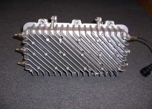
QIUCXP-MVA-GWY
Sep 27, 2006Corinex Medium Voltage Access Gateway
Equipment Class
BPL - Access Broadband Over Powerline System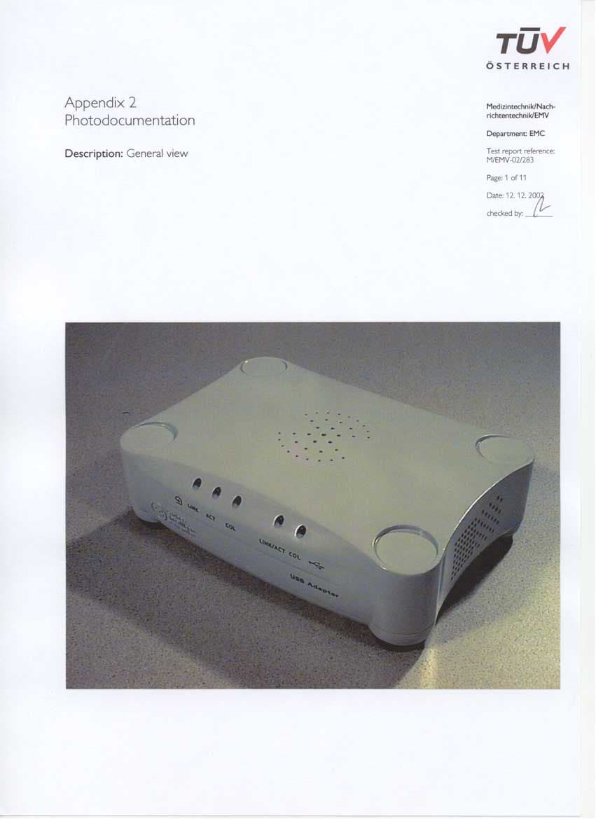
QIUPOWERNET-USB
Jan 30, 2003Powerline Telecommunication Modem for USB
Equipment Class
JBP - Part 15 Class B Computing Device Peripheral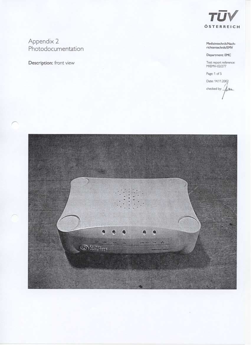
QIUPOWERNET-ETH
Jan 02, 2003Powerline Telecommunication Modem for Ethernet-LAN
Equipment Class
JBP - Part 15 Class B Computing Device Peripheral