QKRRAD255-256Doppler Effect Motion Detector
Agtatec Ag
Click to zoom
Application Details
- Equipment Class
- FDS - Part 15 Field Disturbance Sensor
- Date of Grant
- Aug 20, 2002
- Application Purpose
- Original Equipment
- Date of Application
- Aug 20, 2002
- Equipment Note
- Doppler Effect Motion Detector
- Frequency Range
- 24160.00000000 - 24160.00000000
- Company
- Agtatec Ag
- Country
- Switzerland
Documents & Files
Document Text
Text extracted from the exhibit documents filed with the FCC. Open a document above to read the original.
Users Manual
Montage- und Einstell- anleitung Mounting and adjustment instructions Instructions pour montage et réglages Istruzioni di montaggio e regolazione 16.863 C Radar 255: standard Radar 256: richtungs- erkennend Radar 255: standard Radar 256: direction- detection Radar 255: standard Radar 256: reconnaissance de la direction RADAR 255: standard RADAR 256: identificazione della direzione 1 Teilebezeichnung 1 Description 1 Description 1 Descrizione dettagliata 1 Gehäuseboden 2 Haube 3 Radarprint 4 Antenne 5 Antennenhalterung 6 Befestigungsschraube für Antenne 7 Anschlusskabel 8 Kontroll-LED 9 DIP-Schalter für Modus- einstellung 10 Poti für Empfindlichkeit 1 Bottom of housing 2 Cover 3 Printed board of radar 4 Antenna 5 Antenna fixture 6 Fixing screw for antenna 7 Connection wire 8 Controlling LED 9 DIP-switch for mode- configuration 10 Sensitivity potentiometer 1 Support 2 Couvercle 3 Circuit imprimé radar 4 Antenne 5 Fixation de l’antenne 6 Vis pour fixation de l’antenne 7 Raccordement 8 LED de contrôle 9 Interrupteur DIP pour le réglage du mode 10 Potentiomètre de sensibilité 1 Cassa 2 Coperchio 3 Print del RADAR 4 Antenna 5 Supporto dell'antenna 6 Vite di fissaggio per antenna 7 Cavo d'allacciamento 8 Lampadina LED di controllo 9 Interruttore DIP per il riponimento del modo 10 Potenziometro per la regola- zione della sensibilità 2 Technische Daten 2 Technical data 2 Caractéristiques techniques 2 Dati tecnici Speisespannung: 16...26 VDC Anschlussleistung: ca. 1.8 W Max. Anschlussabsicherung bei Fremdspeisung: 2.5 A Temp. Bereich: –20...+50 °C Betriebsfrequenz: 24.125 GHz (K-Band) Ausgangsleistung: 5 mW Anschlusskabellänge: 2.5 m Supply voltage: 16...26 VDC Connected load: 1.8 W approx. Max. fuse protection if separately supplied : 2.5 A Temp. range: –20...+ 50 °C Frequency: 24.125 GHz (K-band) Power output: 5 mW Wire length: 2.5 m Tension d’alimentation: 16...26 VDC Consommation: 1.8 W environ Protection de raccordement max. lors d'une alimentation externe: 2.5 A Température.: –20...+50 °C Fréquence: 24.125 GHz (bande K) Puissance de sortie: 5 mW Longueur du câble: 2.5 m Tensione di alimentazione: 16...26 VDC Potenza: ca. 1.8 W Protezione di collegamento massimo in occasione di un' alimentazione esterna: 2.5 A Campo di temp.: –20...+50 °C Frequenza: 24.125 GHz (banda K) Potenza di uscita: 5 mW Lunghezza del cavo d'allaccia- mento: 2.5 m 3 Zubehör 3 Accessories 3 Accessoires 3 Accessori A Montagekonsole für Befestigung an der Decke. A Bracket for mounting to ceiling. A Console pour fixation au plafond. A Mensola per fissaggio al soffitto. B Wetterhaube für Wetterschutz des Radars. B Weather shield. B Protection pour protéger le radar contre les intempéries. B Calotta meteorologica. C Montageplatte für Befestigung an gewölbten oder rauhen Oberflächen. C Mounting plate for fixing to circular or rough surfaces. C Plaque de montage pour fixation aux surfaces courbes ou rugueuses. C Piastra di montaggio per montaggio su superfici non piane o sferiche. C B Radar 255/256 Standard Erfassung aller Bewegungen im Bereich der Antennenkeule. Radar 255 standard Detects all movements in the range of the antenna cone. Radar 255 standard Détection de tous les mouvements dans la zone de déclenchement de l’antenne. RADAR 255 standard Rilevamento di tutti i movimenti nel settore dell'antenna. Radar 255/256 Querverkehrsausblendung Verhindert die Erfassung von parallel zur Türe verlaufenden Bewegungen. Radar 255/256 mask of cross traffic Movements parallel to the radar are not detected. Radar 255/256 Suppression du trafic transversal Des mouvements parallèles au radar ne sont pas détectés. RADAR 255/256 Soppres- sione del traffico trans- versale Impediscé l’afferrata del movimento parallelo della porta Radar 256 richtungserkennend (ohne Automode) Erfassung nur Bewegungen zum Radar hin im Bereich der Antennenkeule. Bewegungen vom Radar weg werden nicht erfasst. Radar 256 direction- detection (without automode) Detects only movements towards the radar in the range of the antenna cone. Movements away from the radar are not detected. Radar 256 reconnaissance de la direction (sans automode). Les mouvements sont détectés uniquement lorsqu’ils sont en direction du radar dans la zone de déclenchement de l'antenne. Les mouvements dans la direction opposée du radar ne sont pas détectés. RADAR 256 identificazione della direzione (senza automode) Rilevamento dei movimenti nel settore dell'antenna, ma solamente dei movimenti verso l'antenna e non nella direzione contraria. Radar 256 richtungser- kennend (mit Automode) Automode: Zusatzfunktion bei Radar 256 für höhere Sicherheit im Tür-Nahbereich, da sie die Vorteile des richtungserkennen- den Radars 256 mit denen des Radars 255 kombiniert. Radar 256 direction- detection (with automode) Automode: Supplementary function with radar 256 for better security in the door vicinity since it combines the advantages of the direction-detecting radar 256 with those of the radar 255. Radar 256 reconnaissance de la direction (avec automode). Automode: fonction supplémentaire pour le radar 256 uniquement sécurité plus importante dans la zone de proximité de la porte, puisqu’elle combine les avantages du radar 256 unidirectionnel avec ceux du radar 255. RADAR 256 identificazione della direzione (con automode). Automode: Funzione supplementare del RADAR 256 per maggiore sicurezza nel set- tore più vicino alla porta, per combinare le proprietà di identi- ficazione della direzione del RADAR 256 a quelle del RADAR 255. 4 Montageanleitung 4 Mounting instructions 4 Instructions pour montage 4 Istruzioni di montaggio Hinweise: Stabile Befestigung, keine vibrierenden Unterlagen verwenden. Vor Witterungs- einflüssen (Regen, Schnee etc.) schützen. Notice: Do not mount onto vibrating base. Protect against influences of weather (rain, snow, etc.). Recommandation d’utilisation: Fixation stable, ne pas utiliser des supports vibrants. Protéger contre les intempéries (pluie, neige, etc.) Indicazioni: Non utiliz…
Text truncated - open the document above for the full version.
Cover Letter(s)
August 21, 2002 CONFIDENTIALITY REQUEST Federal Communications Commission Authorization and Evaluation Division 7435 Oakland Mills Road Columbia, MD 21046 Re: agtatec ag, FCC ID: QKRRAD255-256 Gentlemen: Agtatec ag., herein submits a request for Confidentiality for the specified attachments that are filed for FCC ID:QKRRAD255-256. Certification is sought under the TCB certification program pursuant to the requirements of the Federal Communications Commission under FCC Rules Part 15. agtatec ag, requests, pursuant to 47CFR 0.459, post grant confidentiality for portions of the material contained in this application such that the identified material will be withheld from public inspection by the Commission following the grant of this authorization. This material, as indicated by request for confidentiality of the item during the electronic submission process and further identified below, includes: 1.Circuit diagrams and PCB submitted as Equipment Authorization Electronic Filing attachment: "schematics”. 2.Block diagram and operational description submitted as Equipment Authorization Electronic Filing attachment: “blockdiagram”. If you have any questions, please feel free to contact me at the address shown below. Regards, (signed) Gerald Schmidt, Cetecom ICT GmbH, Untertürkheimer Strasse 6-10 D-66117 Saarbrücken Germany Email: [email protected] Phone: +49 681 598 8723
ID Label/Location Info
LABEL: LABEL POSITION:
Internal Photos
RAD255TOPview RAD255Bottomview RAD256Bottomview
Operational Description
Emitter Antenna GUN- Receiver 24.150 GHz Amplifier & Bandpass (30Hz ... 400Hz) Moving Target uP Detection Algorithm RAD 255 / RAD256 Block diagram RAD255 / 256 Description : A fix installed motion detector, short range device with an internal, integral horn antenna, placed on a pc-board, emitting continuously at 24.050 .... 24.250 GHz at a power of less than 20 dBm (less than 100mW). The reflected waves from a moving target (Doppler effect) are detected by a gun diode, are electronically filtered, amplified and evaluated by a microprocessor. If detection is evaluated, either a relais output or an electronically output is activated. Gun Oscillator 24.050 ... 24.250 GHz Power Supply activation of contact
Test Report
CETECOM ICT Services GmbH Radio Satellite Communication Untertürkheimer Straße 6-10 . D-66117 SaarbrückenTelefon: +49 (0)681 598-0Telefax: -9075 RSC11issue test report consist of26 Pages Page 1 (26) Accredited Bluetooth Test Facility (BQTF) Test report no.: 2_2941-01-01/02 FCC Part 15.245 RAD 255 / RAD 256 FCC ID: QKRRAD255-256 CETECOM – ICT Services GmbH Untertürkheimerstr. 6-10 66117 Saarbrücken, Germany Telephone: +49 (0) 681 / 598-0 Fax: +49 (0) 681 / 9075 TTI-P-G166/98 CETECOM ICT Services GmbH Test report nr.:2_2941-01-01/02Issue date: 2002-08-13 Page 2 (26) Table of Contents 1 General information 1.1 Notes 1.2 Testing laboratory 1.3 Details of applicant 1.4 Application details 1.5 Test item 1.6 Test standards 2 Technical test 2.1 Summary of test results 2.2 Test report 1 General information 1.1 Notes The test results of this test report relate exclusively to the test item specified in 1.5. The CETECOM ICT Services GmbH does not assume responsibility for any conclusions and generalisations drawn from the test results with regard to other specimens or samples of the type of the equipment represented by the test item. The test report may only be reproduced or published in full. Reproduction or publication of extracts from the report requires the prior written approval of the CETECOM ICT Services GmbH. 1.2 Testing laboratory CETECOM ICT Services GmbH Untertürkheimer Straße 6 - 10 66117 Saarbrücken Germany Telefone: +49 681 598 - 9100 Telefax: +49 681 598 - 9075 E-mail: [email protected] Internet:www.cetecom.de Accredited testing laboratory The Test laboratory (area of testing) is accredited according to DIN EN ISO/IEC 17025. DAR registration number: TTI-P-G-166/98 Accredited Bluetooth™ Test Facility (BQTF) BLUETOOTH is a trademark owned by Bluetooth SIG, Inc. and licensed to CETECOM CETECOM ICT Services GmbH Test report no.:2_2941-01-01/02Issue date:2002-08-13 Page 3 (26) 1.3 Details of applicant Name :Agtatec AG Street :Allmendstrasse 24 City :8320 Fehraltorf Country : Switzerland Telephone: +41 1 954 92 50 Telefax :+41 1 995 60 14 Contact : Mr. Beat Kuster Telephone: +41 1 954 92 50 1.4 Application details Date of receipt of application : 2002-08-08 Date of receipt of test item: 2002-08-08 Date of test: 2002-08-08 1.5 Test item Type of equipment: Field disturbance sensor for door opening Type designation: Model : RAD 255 / RAD 256 Manufacturer: - applicant - Street: City: Country: Serial number: 88128 (RAD 256) Additional informations: : Frequency: 24.160 GHz Type of modulation: 200kN0NN Number of channels: 1 Antenna: integral dielectrical antenna Power supply: 24V DC external Output power cond.: 13.04 dBm / 20.14mW or 109.7 dBμV/m / 305.5 mV/m at 3m Type of equipment: Class B Temperature range: 0°C - +35°C FCC IDQKRRAD255-256 1.6 Test standards:FCC Part 15 §15.245 CETECOM ICT Services GmbH Test report no.:2_2941-01-01/02Issue date:2002-08-13 Page 4 (26) 2Technical test 2.1 Summary of test results There are two different type of equipment: RAD255 and RAD 256. The only difference is in the receiver part. RAD 255 has 1 RX-diode, RAD 256 has two. We tested the higher equiped RAD 256. The radiated measurements were performed vertical and horizontal over the whole frequency range. We start at 1 m high with vertical receiving antenna and rotate the dish continuously. During rotation we use the antenna lift system to vary the high from 1 to 4 m. So we find maximum radiation output. At this points we do manual re-measurements. After this we repeat measurements in horizontal position of the receiving antenna. This (horizontal and vertical) is made for all the three planes of the test sample. We use the maximum received results. The detector function and selection of bandwidth are according ANSI C63.2-1996 item 8.2.1 and ANSI C63.4-1992 Item 4.2. Antennas are conform with ANSI C63.2-1996 item 15. 30 MHz - 200 MHz: Quasi Peak measurement, 120 kHz Bandwidth, biconical antenna 200 MHz – 1 GHz: Quasi Peak measurement, 120 kHz Bandwidth, log periodic antenna >1 GHz: Average, RBW / VBW≥ ≥≥ ≥1 MHz, waveguide horn and standard gain horns. In order to show evidence it can be necessary to reduce the resolution bandwidth and /or measuring distance and/or to use a low-noise microwave amplifier. Spurious emissions and output power above 12 GHz are measured with calibrated standard gain horns at distances of 0.5 m / 1 m and recalculated to 3 m by reducing the levels by 15.6 dB / 9.5 dB. All measurement settings are according to FCC 15.35, 15.205, 15.209 and 15.245. Test result: No deviations from the technical specification(s) were ascertained in the course of the tests performed. Final verdict : PASS Technical responsibility for area of testing : 2002-08-09RSC 8414 Ames H. DateSection NameSignature Technical responsibility for area of testing : 2002-08-09RSC 8412 Hausknecht D. DateSection NameSignature CETECOM ICT Services GmbH Test report no.:2_2941-01-01/02Issue date:2002-08-13 Page 5 (26) 2.2 Test report TEST REPORT Test report no. : 2_2941-01-01/02 CETECOM ICT Services GmbH Test report no.:2_2941-01-01/02Issue date:2002-08-13 Page 6 (26) TEST REPORT REFERENCE LIST OF MEASUREMENTS Paragraph PARAMETER TO BE MEASUREDPAGE Transmitter parameters § 15.245 (b) Field strength of fundamental frequency7 § 15.245 (b)(3) Spurious emissions outside band9 Output variation over temperature16 Band edge compliance17 Test equipment listing18 Measurement set-ups20 Photographs of the equipment24 CETECOM ICT Services GmbH Test report nr.:2_2941-01-01/02Issue date: 2002-08-13 Page 7 (26) Field strength of fundamental frequency (wanted carrier)§15.245(b) radiated TEST CONDITIONSField strength Frequency (MHz)24160 T nom ( 23.4 )° °° °C V nom ( 24.0)V 305.5 mV/m 109.7 dBμV/m ( = 102 dBpW ) Measurement uncertainty± 4 dB Measuring distance calculated to 3m RBW / VBW :≥ ≥≥ ≥1MHz/1MHz LIMITSUBCLAUSE §15.245 (b) 24075 – 24175 MHz 2500 mV/m or 127.96 dBμV/m at 3 m distance (120.5 dBpW) CETECOM ICT Services GmbH Test report no.:2_…
Text truncated - open the document above for the full version.
Contact Information
Applicant
Kuster Beat(Leader R&D)
Test Firm
Cetecom ICT Services GmbHRalf Hoehn
Technical Specifications
| # | Rule Parts | Frequency Range | Power Output |
|---|---|---|---|
| 1 | 15.245 | 24.16 GHz - 24.16 GHz | - |
Other Applications from Agtatec Ag

QKR-IPQ420US
Jan 17, 2008K-Band Transceiver
Equipment Class
FDS - Part 15 Field Disturbance Sensor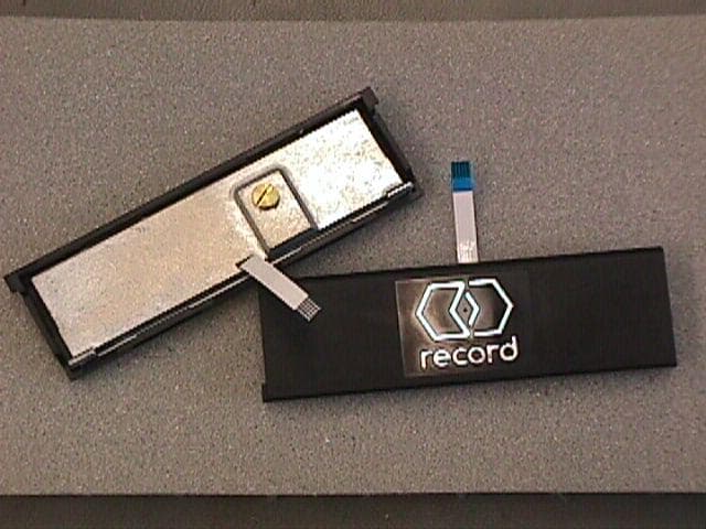
QKRRAD270
Jan 12, 2003Doppler Effect Motion Detector
Equipment Class
FDS - Part 15 Field Disturbance Sensor