QL4G5S6ARadar Detector
Beltronics USA Inc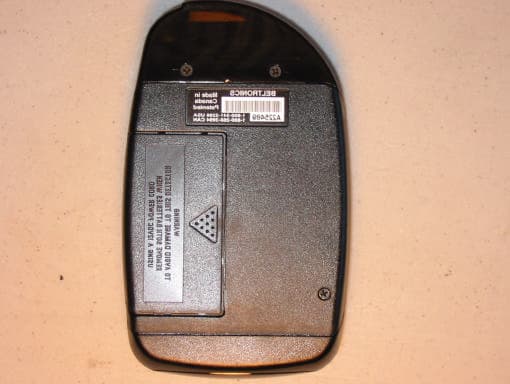
Click to zoom
Application Details
- Equipment Class
- CRD - Part 15 Radar Detector
- Date of Grant
- Sep 08, 2002
- Application Purpose
- Original Equipment
- Date of Application
- Sep 08, 2002
- Equipment Note
- Radar Detector
- Frequency Range
- 33400.00000000 - 35916.00000000
- Company
- Beltronics USA Inc
- Country
- United States
Documents & Files
Document Text
Text extracted from the exhibit documents filed with the FCC. Open a document above to read the original.
Users Manual
with 65 Digital Voice Messages and Digital Display Operating instructions for model E936CS TM Ultimate Performance. Proven Technology. P R O T E C T I O N P R O T E C T I O N 360 ̊ Thank you for purchasing an EXPRESS 936 Radar/Laser/Safety detector. EXPRESS 936 offers the most advanced technology available for detecting all Radar and Laser speed monitoring devices. In addition, EXPRESS 936 features Digital Voice, Text Message Display and the Safety Warning System ® with 60 Digital Voice messages. To ensure maximum benefit from your new unit, please read all instructions before operating your unit. Remember, owning a Radar detector does not give you a license to speed. Alerts from a Radar detector serve as an effective reminder to check your speed. Laws vary throughout North America governing the use of a Radar detector. It is your responsibility to follow these laws. Safety Warning System ® (sws ™ ) EXPRESS 936 detects encoded signals from sws ™ transmitters and provides 60 messages for: Highway Construction/Maintenance, Highway Hazard Zones, Weather Related Hazards, Travel Information/Convenience and Emergency/Slow Moving Vehicles. For a complete description of sws ™ audio and visual alerts, see page 18. VG-2 Guard ® Alert EXPRESS 936 features VG-2 Guard ® , to detect signals from the Interceptor VG-2 (Radar Detector Detector). For a complete description of the VG-2 Guard ® audio/visual alert, see page 17. Safety Warning System ® with Digital Voice Messages Choose between Digital Voice Messages with a unique sws ™ tone or sws ™ tone only (see page 9). Radar/Laser Digital Voice Prompts Choose between Radar/Laser Digital Voice prompts followed by “beeps” or “beeps” only (see page 9). INTRODUCTION SELECTABLE FEATURES 2 3 Profile of Features➤page 4 Description of Features➤page 5 Power Up Test Sequence ➤page 5 Tutorial Mode ➤page 5 Memory Retention of Feature Selections ➤page 6 Adjusting the Audio Level ➤page 6 DRK (Dim/Dark) Button ➤page 6 AUD (Audio Mute) Button ➤page 7 CTY (City/Highway) Button ➤page 8 Reset to Factory Settings ➤page 8 Selectable Features➤page 9 Entering Selectable Features Mode ➤page 9 Installation➤page 10 General Guidelines ➤page 10 Understanding Radar, Laser and sws ™ ➤page 13 Interpretation of Alerts➤page 14 Radar Alerts ➤page 14 Instant-On/Pulsed Radar Alert ➤page 16 Typical False Alert (Radar) ➤page 16 Laser Alerts ➤page 17 Safety Warning System ® (sws ™ ) Alerts ➤page 17 Performance Verification➤page 19 Conditions That Affect Radar Alerts ➤page 19 Conditions That Affect Laser Alerts ➤page 19 Troubleshooting➤page 20 Consumer Warranty➤page 21 Service➤page 22 Warranty Service ➤page 22 Post-Warranty Service ➤page 22 Specifications➤page 23 Accessories➤page 23 TABLE OF CONTENTS 1. P/V(Power/Volume) Button:pressing P/Vbriefly will turn the unit ON. Pressing P/Va second time will bypass the power up test sequence. Pressing P/Vand holding will change the audio level. 2. Text Message Display:communicates all mode selections (i.e. DIM, DARK, CITY, HIGHWAY, and AUTOMUTE) and confirms Radar band and signal strength, presence of Laser and sws ™ messages received. 3. DRK(Dim/Dark) Button:provides dim or dark settings of the Text Display for discreet night travel. Audio alerts are not affected. 4. AUD (Audio Mute) Button:provides automatic and manual muting of X, K, Super Wideband Ka Radar and manual muting of sws ™ alerts. 5. CTY(City/Highway) Button:minimizes unwanted X band alerts without reducing sensitivity. 6. Antenna Opening:Radar and sws ™ signals are received by a patented diecast antenna with integrated transition to microstrip mixer. PROFILE OF FEATURES 4 1 7 6 8 5 4 3 2 9 7. Laser Optical Sensors:collect Laser signals from in front and behind. 8. Audio Alert Speaker:all audible alerts and Digital Voice Messages are emitted from this location. 9. Power Jack:using the straight or coiled cord, EXPRESS 936 operates in any vehicle with a 13.8 volt DCnegative ground system (l0.5 volt to 16 volt range). Power-Up Test Sequence Each time your detector is turned ON, audio and Text Messages for Laser, Ka, K, X and Safety Warning System ® (sws ™ ) are presented. After this sequence, the status of Selectable Features is displayed: “SWS on”, “SWS off”, “VG-2 on”, “VG-2 off”, “SWSvoice”, “SWSclick”, ”VOICEon”, “VOICEoff” (see page 9). If your unit displays information other than this standard power-up test sequence, return it to BELTRONICS for servicing. To bypass the power-up test sequence, press the P/Vbutton during the Power up test sequence. Tutorial Mode The tutorial mode allows you to become more familiar with all audible and visual alerts. To engage this mode, press and hold CTY, then press AUD while the unit is OFF. The message “TUTORIAL” appears in the display followed by the audio and corresponding Text Message for “LASER”, “Ka AUDIO”, “K AUDIO”, “X AUDIO”,”VG-2 Alert,” sample Radar alert (K band signal ramping from weak to strong) and “SAFETY WARNING SYSTEM SAMPLE ALERTS”. Three sample sws ™ messages are then presented in the display along with the corresponding Digital Voice Message: Sample 1 “ACCIDENT AHEAD” Sample 2 “HIGHWAY WORKCREW AHEAD” Sample 3 “POLICE IN PURSUIT” Anytime during Tutorial Mode (except Safety Warning System ® DESCRIPTION OF FEATURES 5 sample alerts) press CTY or AUDto move forward or backward through the alerts. During sws ™ sample alerts press CTYto move forward in the sws ™ message list. “MSG 1”will appear initially in the display confirming your selecion. Pressing the AUDbutton allows you to listen to the sws ™ message while viewing it in the display. Press the CTYbutton again to step to the next message; press the AUDbutton to review, and so on. This allows you to review all 60 messages. To exit Tutorial Mode, press the P/V button and your unit will be ONand ready to receive signals. Memory Retention of Feature Selections Any time EXPRESS 936 is turned OFFor unplugged from the cigarette lighter socket, all feature settings are retained in the uni…
Text truncated - open the document above for the full version.
Users Manual
Modifications not expressly approved by the manufacturer could void the user’s FCC granted authority to operate the equipment. Printed in Canada153003-00 11263_FCC card insert 8/28/02 5:06 PM Page 1 11263_FCC card insert 8/28/02 5:06 PM Page 2
External Photos
External Photos Model: Express Cordless 946 FCC ID: QL4G5S6A Model: Express Cordless 946 FCC ID: QL4G5S6A Model: Express Cordless 946 FCC ID: QL4G5S6A Model: Express Cordless 946 FCC ID: QL4G5S6A
External Photos
External Photos Model: Express Cordless 946 FCC ID: QL4G5S6A Model: Express Cordless 946 FCC ID: QL4G5S6A Model: Express Cordless 946 FCC ID: QL4G5S6A Model: Express Cordless 946 FCC ID: QL4G5S6A
Internal Photos
Internal Photos Model: Express Cordless 946 FCC ID: QL4G5S6A Model: Express Cordless 946 FCC ID: QL4G5S6A Model: Express Cordless 946 FCC ID: QL4G5S6A
Internal Photos
Internal Photos Model: Express Cordless 946 FCC ID: QL4G5S6A Model: Express Cordless 946 FCC ID: QL4G5S6A Model: Express Cordless 946 FCC ID: QL4G5S6A
Test Report
Company: Beltronics USA, Inc. FRN: 0007600588 Model: Express Cordless 946 FCC ID: QL4G5S6A Equipment Code: CRD Report prepared for: Report prepared by: Beltronics USA, Inc. Evan D. Gould 5442 West Chester Road Curtis-Straus LLC West Chester, OH 45069 527 Great Road Phone: (513)-870-8535 Phone: (978)-486-8880 FAX: (513)-870-8523 FAX: (978)-486-8828 EMC Manager Worldwide Regulatory Approvals Experts (A2LA Certificate Number 1627-01) Technical Report REPORT:C0610-5 FCC ID:QL4G5S6A Page 2 of 8 Introduction This report is an application for Certification of a Radar Detector operating pursuant to 47 CFR 15.109, as amended by ET Docket No. 01-278; FCC 02-211, published in the Federal Register Vol. 67, No. 145 on Monday July 29, 2002. REPORT:C0610-5 FCC ID:QL4G5S6A Page 3 of 8 Statement of Conformity 47 CFR 15.109(h) states that “Radar detectors shall comply with the emissions limits...of [section 15.109(a)] over the frequency range of 11.7 – 12.2GHz.” The applicable limit being 500μV/m measured at a distance of 3m. The Beltronics Express Cordless 946 has been tested and found to comply with this requirement: REPORT:C0610-5 FCC ID:QL4G5S6A Page 4 of 8 Test Methodology Radiated emission testing was performed according to the procedures in ANSI C63.4 (2001). The testing was performed at an antenna to EUT distance of 1 meter. Performance was investigated in the range 11.7-12.2GHz. The Express 946 was powered a R.O.C. SPN4025A 12VDC 400mA power supply using the optionally available DC input jack. Since the device is a hand-held unit, the emissions were maximized around the three orthogonal axes and the maximum reading was recorded. The integrated antenna cannot be maximized separately. REPORT:C0610-5 FCC ID:QL4G5S6A Page 5 of 8 Test Equipment SPECTRUM ANALYZERS x Analyzer Model No. Company Serial No. Calibration Due X ORANGE 9kHz-26.5GHz E4407B HP US39440975 07-JUN-2003 OPEN AREA TEST SITES (OATS) x Site FCC Code IC Code VCCI Code Calibration Due X “M” Maine 93448 IC 2762-M R-904/ C-480 04-FEB-2004 ANTENNAS x Antenna Model No. Company Serial No. Calibration Due X YELLOW Horn: 1-18GHz 3115 EMCO 9608-4898 08-MAY-2003 PREAMPLIFIERS / ATTENUATORS x Preamplifier Model No. Company Serial No. Calibration Due X ORANGE-BLACK 1-20GHZ SMC-12A MITEQ 690639 06-SEP-2002 Unless otherwise noted the calibration interval is one year. All equipment is calibrated using standards traceable to NIST or other nationally recognized calibration standard. All Open Area Test Sites are located at 527 Great Road, Littleton, MA 01460. REPORT:C0610-5 FCC ID:QL4G5S6A Page 6 of 8 Setup Photo Model: Express 946 REPORT:C0610-5 FCC ID:QL4G5S6A Page 7 of 8 Measurement Results All measurements taken were peak detector readings of the noise floor. There were no emissions detected from the EUT. Radiated Emissions Table Curtis-Straus LLC Date:23-Aug-02Company:BeltronicsTable1 Engineer:Evan GouldEUT Desc:Express Cordless 946Work Order:C0610 Frequency Range:11.7-12.2GHzMeasurement Distance:1 m Notes:Emissions maximized Horizontally and Vertically. All measurements are noise floor readings. AntennaPreampAntennaCableAdjusted47 CFR 15.209(a) PolarizationFrequencyReadingFactorFactorFactorReadingLimitMarginResult (H / V)(MHz)(dBμV)(dB)(dB/m)(dB)(dBμV/m)(dBμV/m)(dB)(Pass/Fail) E94611901.032.420.339.04.755.863.5-7.7Pass Test Sites:"M"Pre-Amp:Or-BlkCable:3m MicroflexAnalyzer:OrangeAntennas:Yellow Horn REPORT:C0610-5 FCC ID:QL4G5S6A Page 8 of 8 Emission Plot
Contact Information
Applicant
John Kuhn(Vice President, Engineering)
Test Firm
Curtis-Straus LLCJonathan Stewart
Technical Specifications
| # | Rule Parts | Frequency Range | Power Output |
|---|---|---|---|
| 3 | 15B | 33.40 GHz - 35.92 GHz | - |
Other Applications from Beltronics USA Inc
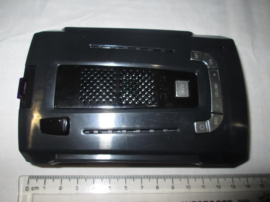
QL4G7M5
Sep 30, 2015Radar Detector
Equipment Class
CRD - Part 15 Radar Detector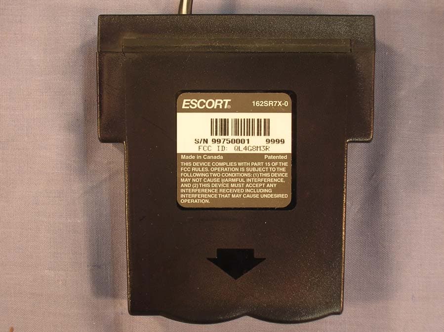
QL4G8M3R
Jun 14, 2007Radar Detector
Equipment Class
CRD - Part 15 Radar Detector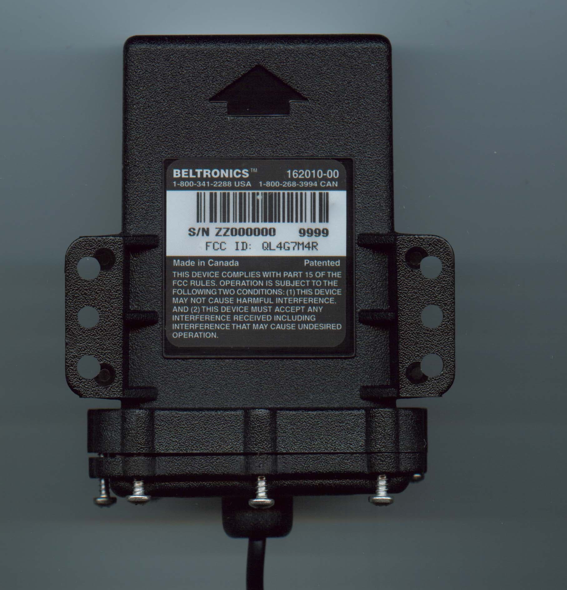
QL4G7M4R
Aug 27, 2006Radar Detector
Equipment Class
CRD - Part 15 Radar DetectorQL4G8M3
Sep 18, 2005Radar Detector
Equipment Class
CRD - Part 15 Radar Detector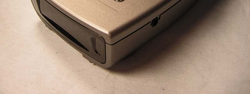
QL4G7M4
Jan 24, 2005Radar Detector
Equipment Class
CRD - Part 15 Radar Detector