QLBPTSS2011TRANSMITTER MODULE
Pegasus Technologies, Inc.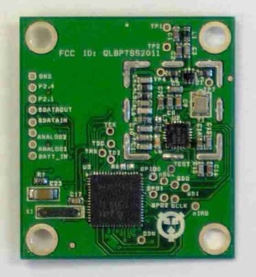
Click to zoom
Application Details
- Equipment Class
- DSS - Part 15 Spread Spectrum Transmitter
- Date of Grant
- Apr 25, 2011
- Application Purpose
- Original Equipment
- Date of Application
- Apr 25, 2011
- Equipment Note
- TRANSMITTER MODULE
- Frequency Range
- 903.00000000 - 927.00000000
- Company
- Pegasus Technologies, Inc.
- Country
- United States
Documents & Files
Document Text
Text extracted from the exhibit documents filed with the FCC. Open a document above to read the original.
Users Manual
Pegasus Technologies, Inc. PTSS2011Transceiver Users Manual (Preliminary) RF Transceiver Installation Instructions The PTSS2011 Transceiver Frequency Hopping Spread Spectrum transceiver. This transceiver should only be installed by qualified service personnel. The transceiver detects level, low battery or other data signals from the external binary inputs and broadcasts that data to the system's host receiver. MOUNTING LOCATION The PTSS2011 Transceiver is a module as defined by the FCC and therefore must be mounted to another host device in order to function. This device is intended only for OEM integrators under the following conditions: 1) The integrator must position this device in any end product such that the antenna to user/bystander distance is greater than 20 cm when the transmitter is functioning (excluding hands, wrists, feet and ankles). 2) The transmitter module may not be co-located with any other transmitter or antenna. As long as the 2 conditions above are met, further transmitter testing will not be required. However, the OEM integrator is still responsible for testing their end-product for any additional compliance requirements required with this module installed (for example, digital device emissions, PC peripheral requirements, etc.). IMPORTANT NOTE: In the event that these conditions can not be met (for example applications where the antenna to user distance is < 20 cm or to be co-located with another transmitter), then the original FCC authorization is no longer considered valid and the FCC ID can not be used on the final product. In these circumstances, the OEM integrator will be responsible for re-evaluating the end product (including the transmitter) and obtaining a separate FCC authorization. NOTICE TO CUSTOMER Any Pegasus Technologies customer incorporating the PTSS2011 transceiver module into its own product must have an external notice affixed to its product. This notice must be placed in a conspicuous location and can use wording such as: “Contains FCC ID: QLBPTSS2011” or “Contains Transceiver Module FCC ID: QLBPTSS2011”. Any similar wording that expresses the same meaning may be used. NOTE: The end user should NOT be provided any instructions on how to remove or install the device. RF Exposure Manual Information That Must be Included to End User The users manual for end users must include the following information in a prominent location "IMPORTANT NOTE: To comply with FCC RF exposure compliance requirements, the antenna used for this transmitter must be installed to provide a separation distance of at least 20 cm from all persons and must not be co-located or operating in conjunction with any other antenna or transmitter." INSTALLATION INSTRUCTIONS 1. Supply the transceiver with DC power by inserting a 3.6 Volt battery into the battery holder on the customers host application circuit board. 2. The unit will come pre-programmed with a Network ID and Hop Seed. However, the customer does have the option of field programming the unit. 3. If possible, avoid installing the PTSS2011 in areas near large metallic objects such as air conditioners, heaters, screens and heaters. CAUTION: This device is required to comply with FCC RF exposure requirements for mobile and fixed transmitting devices. The FCC requires that the antenna used for this transmitter must be installed to provide a separation of at least 20 cm (8 inches) from all persons (not including hands, wrists, feet, and ankles) and must not be co-located or operating in conjunction with any other antenna or transmitter. FCC NOTICE The Model PTSS2011 transceiver generates and uses radio frequency energy. If not installed and used in accordance with the manufacturer's instructions, it may cause interference to radio and television reception. The transceiver has been tested and found to comply with the specifications in Part 15 of FCC Rules for Spread Spectrum Intentional Radiators and FCC Part 15 Subpart C, Specifications. If this equipment causes interference to radio or television reception - which can be determined by turning the equipment on and off - the installer is encouraged to correct the interference by one or more of the following measures: 1) Reorient the antenna of the radio/television. 2) Connect the AC transformer to a different outlet so the control panel and radio/television are on different branch circuits. 3) Relocate the control panel with respect to the radio/television. If necessary, the installer should consult an experienced radio/television technician for additional suggestions, or send for the "Interference Handbook" prepared by the Federal Communications Commission. This booklet is available from the U.S. Government Printing Office, Washington, D.C., 20402, stock number 004-000-00450-7. CAUTION: No field changes or modifications to the PTSS2011 should be made unless they are specifically covered in this manual. All adjustments must be made at the factory under the specific guidelines set forth in our manufacturing processes. Any modification to the equipment could void the user's authority to operate the equipment and render the equipment in violation of FCC Part 15, Subpart C, 15.247. This device complies with Part 15 of the FCC Rules. Operation is subject to the following two conditions: (1) this device may not cause harmful interference, and (2) this device must accept any interference received, including interference that may cause undesired operation. LIMITED WARRANTY THERE ARE NOT WARRANTIES, EXPRESS OR IMPLIED, OF MERCHANTABILITY OR FITNESS FOR A PARTICULAR PURPOSE OR OTHERWISE, WHICH EXTEND BEYOND THE DESCRIPTION ON THE FACE HEREOF. In no case shall Seller be liable to anyone for any consequential or incidental damages for breach of this or any other warranty, express or implied, or upon any other basis of liability whatsoever, even if the loss or damage is caused by Seller's own negligence or fault.
Block Diagram
55 44 33 22 11 D D C C B B A A 903 MHz - 927 MHz VOLTAGEREGULATOR DC INPUT OUTPUTCONNECTOR 3.6VNOM. 903 MHz - 927 MHz ReceiveBalun TransmitBalun TRANSCEIVER ICLOW FDIRECTCONVERSION(937 KHz I.F.) MICROCONTROLLER T/R SWITCHIC 30.0 MHz CRYSTAL 32.768KHZ CLOCKCRYSTAL DATA INPUTSAND OUTPUTS 903 MHz - 927 MHz 903 MHz - 927 MHz 903 MHz - 927 MHz LOW PASSRF FILTER PTSS2011BD 0 PTSS2011 BLOCK DIAGRAM A 1 1 Tuesday, January 21, 2003 TitleSize Document Number Rev Date: Sheet of +3 VOLTS
Cover Letter(s)
Pegasus Technologies Inc. 108 Pawnook Farm Road Lenoir City, TN 37771 Phone 865-483-7748 Fax 775-261-0914 Email [email protected] AGENCY AGREEMENT Federal Communications Commission Date: P.O. Box 429 Columbia, MD 21045 Gentlemen: I hereby appoint TIMCO Engineering to act as our agent in the preparation of an application for equipment authorization of the PTSS2011 under Part 15 of the FCC Rules and Regulations. I certify that Exhibits ______________ properly describe the device or system for which authorization is sought, that the information described in the User's Manual will be provided with each item manufactured or distributed by the applicant, and that the labels described by Exhibit ______________ will be affixed to each item manufactured or distributed by the applicant. I further certify that appropriate arrangements have been made to assure that production units of this equipment bearing the name and FCC IDENTIFIER listed in this application will continue to comply with the Commission's requirements. I further certify by signature below that no party (per 47 CFR 1.2002(b)) to the application is subject to a denial of Federal benefits, including FCC benefits, pursuant to Section 5301 of the Anti-Drug Abuse Act of 1988, 21 U.S.C. 853(a). This appointment also includes the authority to complete FCC Form 731 on our behalf and sign the application as an authorized agent. Sincerely, James W Pearce, President
Cover Letter(s)
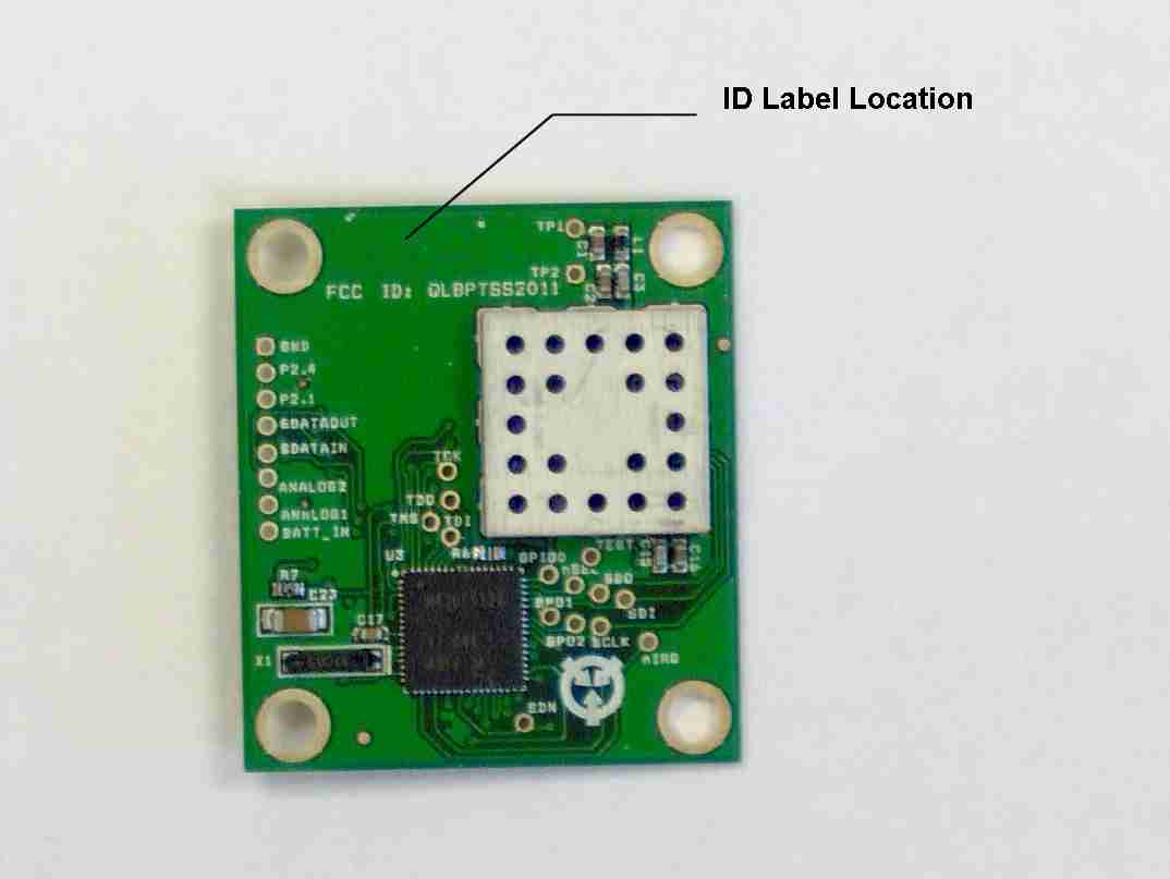
Pegasus Technologies Inc. 108 Pawnook Farm Road Lenoir City, TN 37771 Phone 865-483-7748 Fax 775-261-0914 Email [email protected] Re: modular transmitter approval Gentlemen: Public Notice DA00-1407 regarding Part 15 unlicensed modular transmitters requires that the following information be addressed. The transmitter module is a complete RF transmitter containing its own reference oscillator. The connections available on the module are for power, data and antenna. Below please find information, addressing each paragraph from DA00-1407, requested about the unit. 1.) The unit has its own RF shield to prevent coupling between the RF circuitry of the module and any wires or circuits in the device into which the module is installed. Please see the included photographs. 2.) The unit buffers all input signals through its digital logic. 3.) The unit has power regulation incorporated in the circuitry to ensure continued compliance regardless of the design of the power supplying circuitry. 4.) The unit utilizes a Hirose H.FL connector and stated for use with approved antennas only. This fulfills the requirements of 15.203. 5.) The module was tested in a stand-alone configuration. The module complies with part 15 emissions limits regardless of the device into which it is eventually installed. 6.) The module has the FCC ID number permanently affixed to the printed circuit board and information supplied to the end user regarding label placement on the outside of the device into which the module is contained. This information is clearly defined in the user manual. 7.) The unit complies with part 15.247 as stated in the user manual. Adequate instructions are supplied with the unit to explain the requirements. 8.) The unit complies with the RF exposure requirements as stated in 2.1091, 2.1093, and part 15. Should you require any further information, please contact the undersigned. Thank you for your consideration in this matter. Sincerely, Jim Pearce
External Photos
APPLICANT: PEGASUS TECHNOLOGIES INC. FCC ID: QLBPTSS2011
ID Label/Location Info
CONTAINS FCC ID:QLBPTSS2011 This device complies with Part 15 of FCC rules. Operation is subject to the following conditions:1)This device may not cause harmful interference, and 2) This device must accept any interference received including interference that may cause undesired operation. CONTAINS FCC ID:QLBPTSS2011 This device complies with Part 15 of FCC rules. Operation is subject to the following conditions:1)This device may not cause harmful interference, and 2) This device must accept any interference received including interference that may cause undesired operation. CONTAINS FCC ID:QLBPTSS2011 This device complies with Part 15 of FCC rules. Operation is subject to the following conditions:1)This device may not cause harmful interference, and 2) This device must accept any interference received including interference that may cause undesired operation. CONTAINS FCC ID:QLBPTSS2011 This device complies with Part 15 of FCC rules. Operation is subject to the following conditions:1)This device may not cause harmful interference, and 2) This device must accept any interference received including interference that may cause undesired operation. CONTAINS FCC ID:QLBPTSS2011 This device complies with Part 15 of FCC rules. Operation is subject to the following conditions:1)This device may not cause harmful interference, and 2) This device must accept any interference received including interference that may cause undesired operation. CONTAINS FCC ID:QLBPTSS2011 This device complies with Part 15 of FCC rules. Operation is subject to the following conditions:1)This device may not cause harmful interference, and 2) This device must accept any interference received including interference that may cause undesired operation. CONTAINS FCC ID:QLBPTSS2011 This device complies with Part 15 of FCC rules. Operation is subject to the following conditions:1)This device may not cause harmful interference, and 2) This device must accept any interference received including interference that may cause undesired operation. CONTAINS FCC ID:QLBPTSS2011 This device complies with Part 15 of FCC rules. Operation is subject to the following conditions:1)This device may not cause harmful interference, and 2) This device must accept any interference received including interference that may cause undesired operation. CONTAINS FCC ID:QLBPTSS2011 This device complies with Part 15 of FCC rules. Operation is subject to the following conditions:1)This device may not cause harmful interference, and 2) This device must accept any interference received including interference that may cause undesired operation. CONTAINS FCC ID:QLBPTSS2011 This device complies with Part 15 of FCC rules. Operation is subject to the following conditions:1)This device may not cause harmful interference, and 2) This device must accept any interference received including interference that may cause undesired operation. CONTAINS FCC ID:QLBPTSS2011 This device complies with Part 15 of FCC rules. Operation is subject to the following conditions:1)This device may not cause harmful interference, and 2) This device must accept any interference received including interference that may cause undesired operation. CONTAINS FCC ID:QLBPTSS2011 This device complies with Part 15 of FCC rules. Operation is subject to the following conditions:1)This device may not cause harmful interference, and 2) This device must accept any interference received including interference that may cause undesired operation. CONTAINS FCC ID:QLBPTSS2011 This device complies with Part 15 of FCC rules. Operation is subject to the following conditions:1)This device may not cause harmful interference, and 2) This device must accept any interference received including interference that may cause undesired operation. CONTAINS FCC ID:QLBPTSS2011 This device complies with Part 15 of FCC rules. Operation is subject to the following conditions:1)This device may not cause harmful interference, and 2) This device must accept any interference received including interference that may cause undesired operation. CONTAINS FCC ID:QLBPTSS2011 This device complies with Part 15 of FCC rules. Operation is subject to the following conditions:1)This device may not cause harmful interference, and 2) This device must accept any interference received including interference that may cause undesired operation. CONTAINS FCC ID:QLBPTSS2011 This device complies with Part 15 of FCC rules. Operation is subject to the following conditions:1)This device may not cause harmful interference, and 2) This device must accept any interference received including interference that may cause undesired operation. CONTAINS FCC ID:QLBPTSS2011 This device complies with Part 15 of FCC rules. Operation is subject to the following conditions:1)This device may not cause harmful interference, and 2) This device must accept any interference received including interference that may cause undesired operation. CONTAINS FCC ID:QLBPTSS2011 This device complies with Part 15 of FCC rules. Operation is subject to the following conditions:1)This device may not cause harmful interference, and 2) This device must accept any interference received including interference that may cause undesired operation. CONTAINS FCC ID:QLBPTSS2011 This device complies with Part 15 of FCC rules. Operation is subject to the following conditions:1)This device may not cause harmful interference, and 2) This device must accept any interference received including interference that may cause undesired operation. CONTAINS FCC ID:QLBPTSS2011 This device complies with Part 15 of FCC rules. Operation is subject to the following conditions:1)This device may not cause harmful interference, and 2) This device must accept any interference received including interference that may cause undesired operation. CONTAINS FCC ID:QLBPTSS2011 This device complies with Part 15 of FCC rules. Operation is subject to the following conditions:1)This device may not cause harmful interference, and 2…
Text truncated - open the document above for the full version.
Internal Photos
APPLICANT: PEGASUS TECHNOLOGIES INC. FCC ID: QLBPTSS2011
Operational Description
Antennas for use with PTSS2011 Module: 1. Jyebao ANT-A6/0.902-0.926/1WST or equiv., Vertical Folded Dipole, Gain 1.8 dBi, Reverse polarity SMA connector. 2. Linx ANT-915-CW-QW or equiv., Vertical ¼ Wave Monopole, Gain 0 dBi, Reverse polarity SMA connector.
RF Exposure Info
FCC ID: QLBPTSS2011 SECTION 6 RF EXPOSURE INFORMATION FCC ID: QLBPTSS2011 6.1 RF Safety Requirements to 2.1091 for Mobile and Fixed Transmitters The EUT is being submitted for modular approval. The transmitter is intended to be used in mobile and fixed installations. The unit under evaluation has been tested with antennas with gains up to +3 dBi gain with a measured output power output of 0.032 Watts at the antenna terminals. Taking into consideration the gain of the antenna, the corrected EIRP is 64 mW. The MPE calculations are shown as follows: The limits for this unit (uncontrolled exposure) are 0.6 mW/cm 2 (900 MHz/1500). Taking the RF Density Field Equation: S = EIRP (mW)/(4πR2) and solving for Distance R R = SQRT(EIRP (mW)/(S4π)) Plugging in data yields R (cm) = SQRT (64 (mw)/(0.6 (mW/cm2)*4*π) ) = <3 cm The RF Density equation shows that the minimum separation distance to be 3 cm. Since the EUT is considered by the manufacture to be a mobile unit, which by definition specifies that the antenna distance is greater than 20 cm, the manual therefore incorporates a caution statement that states that the unit should only be used when a separation of 20 cm is maintained between the antenna and users. This ensures compliance with the MPE requirements.
Test Report
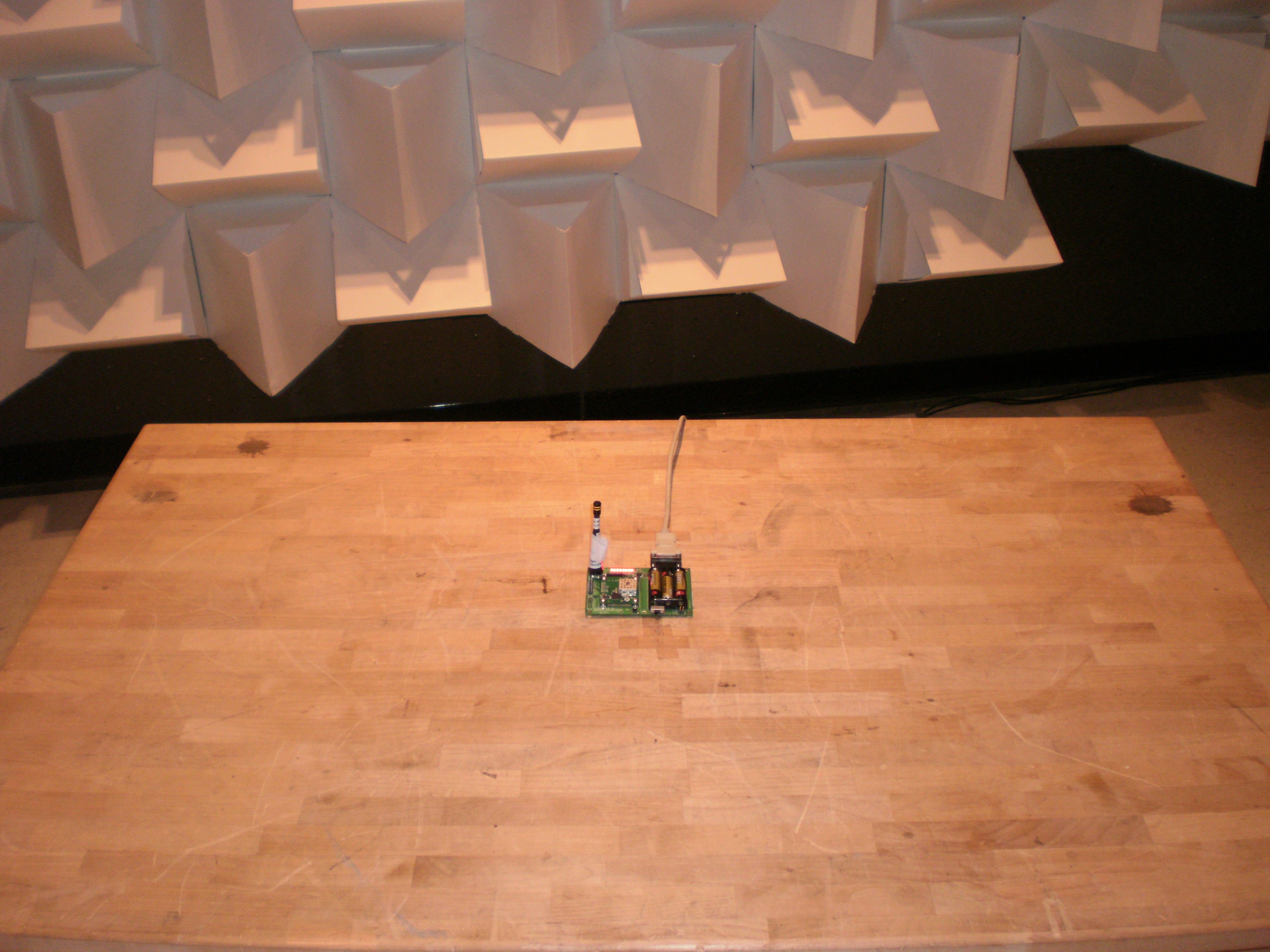
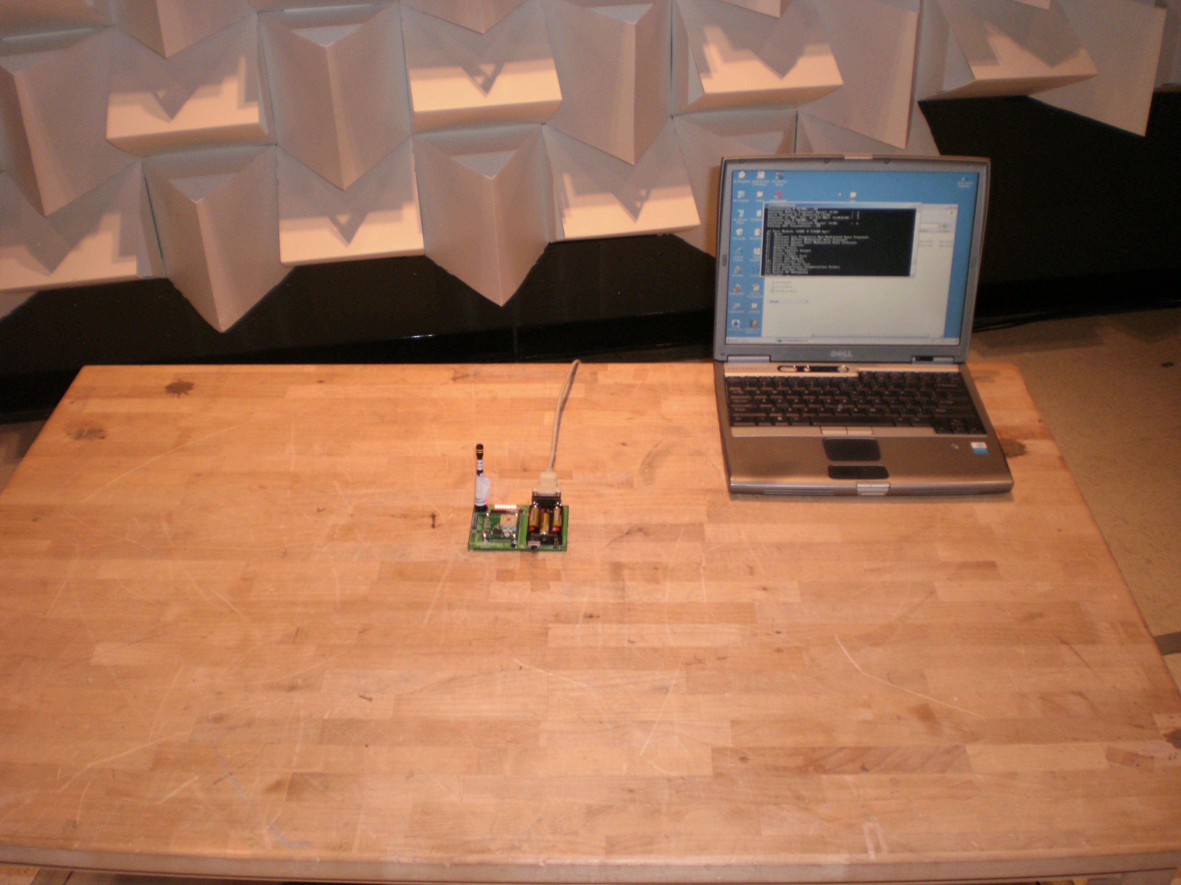
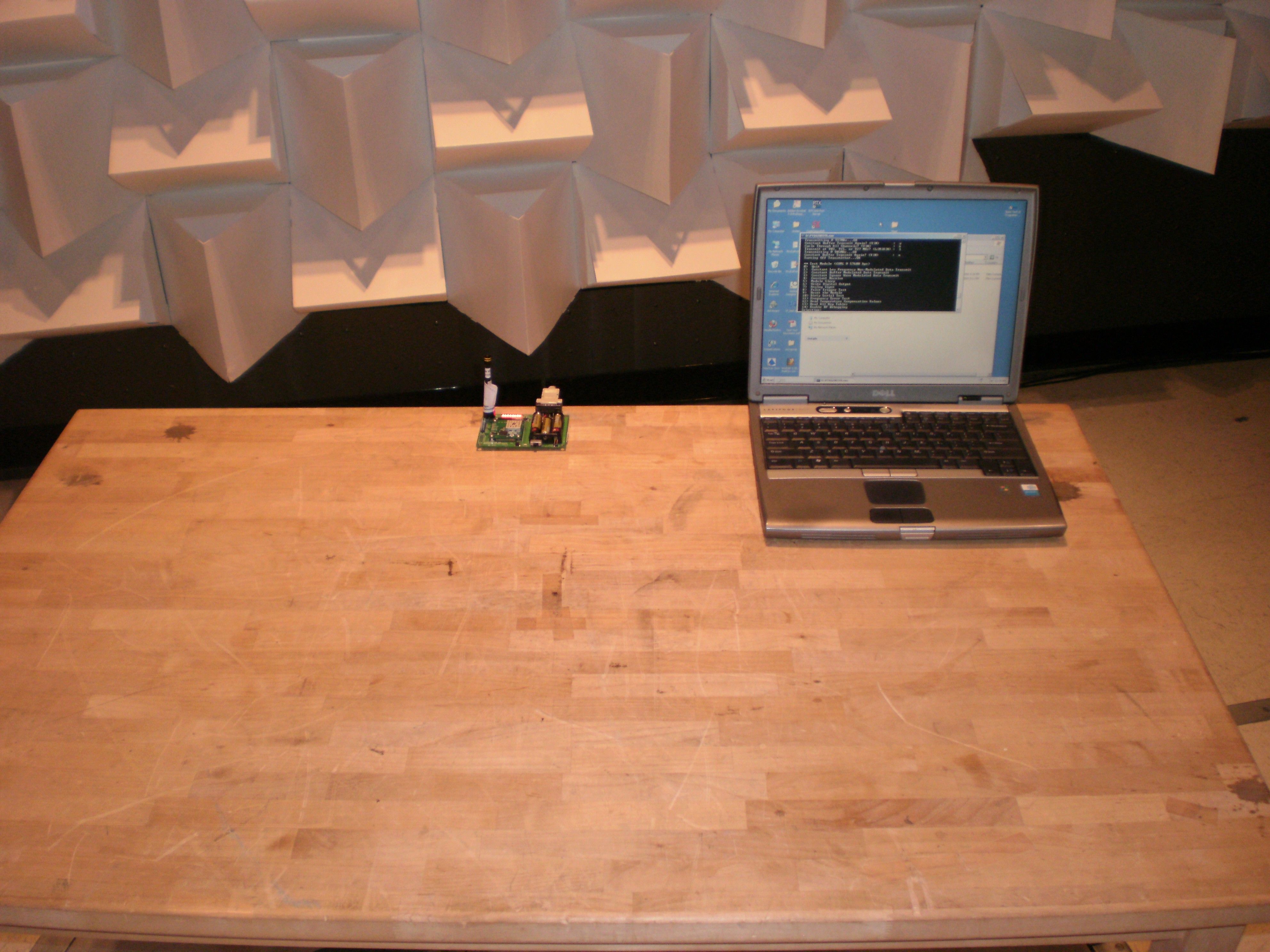
TEST REPORT PER FCC PT 15.247 FHSS APPLICANT PEGASUS TECHNOLOGIES, INC. ADDRESS 108 PAWNOOK FARM ROAD LENOIR CITY TN 37771 USA FCC ID QLBPTSS2011 PRODUCT DESCRIPTION TRANSMITTER MODULE DATE SAMPLE RECEIVED 3/22/2011 DATE TESTED 4/11/2011 TESTED BY Joe Scoglio APPROVED BY Mario R. de Aranzeta TIMCO REPORT NO. 560AUT11TestReport.doc TEST RESULTS PASS FAIL THE ATTACHED REPORT SHALL NOT BE REPRODUCED EXCEPT IN FULL WITHOUT THE WRITTEN APPROVAL OF TIMCO ENGINEERING, INC. 849 NW STATE ROAD 45 NEWBERRY, FL 32669 USA PH: 888.472.2424 OR 352.472.5500 FAX: 352.472.2030 EMAIL: [email protected] HTTP: //WWW.TIMCOENGR.COM Certificate # 0955-01 APPLICANT: PEGASUS TECHNOLOGIES, INC. FCC ID: QLBPTSS2011 REPORT: P\PEGASUS_QLB\560AUT11\560AUT11TestReport.doc Page 2 of 22 073008_mda TABLE OF CONTENTS ATTESTATION .................................................................................................................. 3 REPORT SUMMARY .......................................................................................................... 4 TEST ENVIRONMENT AND TEST SETUP .......................................................................... 4 DUT DESCRIPTION .......................................................................................................... 5 EMC EQUIPMENT LIST ..................................................................................................... 6 TEST PROCEDURES ......................................................................................................... 7 POWER LINE CONDUCTED INTERFERENCE .................................................................... 9 NUMBER OF HOPPING CHANNELS ................................................................................ 10 DWELL TIME OF A HOPPING CHANNEL ......................................................................... 11 20 dB BANDWIDTH ........................................................................................................ 12 CARRIER FREQUENCY SEPARATION ............................................................................. 13 POWER OUTPUT ............................................................................................................ 14 SPURIOUS EMISSIONS AT ANTENNA TERMINALS.......................................................... 15 FIELD STRENGTH OF SPURIOUS EMISSIONS ................................................................ 16 RADIATED SPURIOUS EMISSIONS INTO ADJACENT RESTRICTED BAND ...................... 18 POWER SPECTRAL DENSITY .......................................................................................... 22 APPLICANT: PEGASUS TECHNOLOGIES, INC. FCC ID: QLBPTSS2011 REPORT: P\PEGASUS_QLB\560AUT11\560AUT11TestReport.doc Page 3 of 22 073008_mda ATTESTATION This equipment has been tested in accordance with the standards identified in the referenced test report. To the best of my knowledge and belief, these tests were performed using the measurement procedures described in this report and demonstrate that the equipment complies with the appropriate standards. All instrumentation and accessories used to test products for compliance to the indicated standards are calibrated regularly in accordance with ISO 17025: 2005 requirements. I attest that the necessary measurements were made by me or under my supervision, at Timco Engineering, Inc. located at 849 N.W. State Road 45, Newberry, Florida 32669 USA. Testing Certificate #0955-01 AUTHORIZED BY: Mario de Aranzeta SIGNATURE: FUNCTION: Lab Supervisor/ Test Engineer DATE: 4/20/2011 APPLICANT: PEGASUS TECHNOLOGIES, INC. FCC ID: QLBPTSS2011 REPORT: P\PEGASUS_QLB\560AUT11\560AUT11TestReport.doc Page 4 of 22 073008_mda REPORT SUMMARY Disclaimer: The test results relate only to the items tested. Purpose of Test: To demonstrate that the DUT is compliant with FCC Pt 15.247 requirements for a FHSS radio. Applicable Standards: FCC Pt 15.247, ANSI C63.4: 2003, ANSI TIA-603: 2004, FCC Pt 15.109 Related Reports: N/A TEST ENVIRONMENT AND TEST SETUP Test Facilities: All measurements were made at one or more of the test sites of TIMCO ENGINEERING INC. located at 849 N.W. State Road 45, Newberry, FL 32669. Laboratory Test Conditions: Temperature: 26°C, Humidity: 55% Test Exercise: The DUT was set in continuous transmit mode of operation. Deviation to the Standards: There was no deviation from the standard. Modification to the DUT: No modification was made. Supporting Accessories: None APPLICANT: PEGASUS TECHNOLOGIES, INC. FCC ID: QLBPTSS2011 REPORT: P\PEGASUS_QLB\560AUT11\560AUT11TestReport.doc Page 5 of 22 073008_mda DUT DESCRIPTION DUT Description TRANSMITTER MODULE FCC ID QLBPTSS2011 Frequency 902 to 928 MHz band Modulation Binary FSK DUT Power Source 110–120Vac/50– 60Hz DC Power Battery Operated Exclusively Test Item Prototype Pre-Production Production Type of Equipment Fixed Mobile Portable APPLICANT: PEGASUS TECHNOLOGIES, INC. FCC ID: QLBPTSS2011 REPORT: P\PEGASUS_QLB\560AUT11\560AUT11TestReport.doc Page 6 of 22 073008_mda EMC EQUIPMENT LIST Device Manufacturer Model Serial Number Cal/Char Date Due Date 3-Meter Semi- Anechoic Chamber Panashield N/A N/A Listed 3/10/10 3/10/12 Antenna: Dipole Kit Electro- Metrics TDA-30/1-4 153 CHAR 6/10/09 6/10/11 Frequency Counter HP 5385A 3242A07460 CAL 5/26/09 5/26/11 Modulation Analyzer HP 8901A 3435A06868 CAL 5/26/09 5/26/11 Digital Multimeter Fluke FLUKE-77-3 79510405 CAL 5/18/09 5/18/11 Analyzer Tan Tower Preamplifier HP 8449B-H02 3008A00372 CAL 11/21/09 11/21/11 Analyzer Tan Tower Quasi- Peak Adapter HP 85650A 3303A01690 CAL 11/22/09 11/22/11 Analyzer Tan Tower RF Preselector HP 85685A 3221A01400 CAL 11/21/09 11/21/11 Analyzer Tan Tower Spectrum Analyzer HP 8566B Opt 462 3138A07786 3144A20661 CAL 11/24/09 11/24/11 Temperature Chamber Tenney Engineering TTRC 11717-7 CHAR 4/25/10 4/25/12 APPLICANT: PEGASUS TECHNOLOGIES, INC. FCC ID: QLBPTSS2011 REPORT: P\PEGASUS_QLB\560AUT11\560AUT11TestReport.doc Page 7 of 22 073008_mda TEST PROCEDURES POWER LINE CONDUCTE…
Text truncated - open the document above for the full version.
Contact Information
Applicant
Jim Pearce(President)
Test Firm
Timco Engineering, Inc.Bruno Clavier
Technical Specifications
| # | Rule Parts | Frequency Range | Power Output |
|---|---|---|---|
| 1 | 15C | 903 MHz - 927 MHz | 32.00 mW |
Other Applications from Pegasus Technologies, Inc.
QLBPT11MH
Aug 29, 2007FHSS TRANSMITTER
Equipment Class
DSS - Part 15 Spread Spectrum Transmitter
QLBPTSS2003LP
Mar 29, 2004900 MHz Frequency Hopping Spread Spectrum Module
Equipment Class
DSS - Part 15 Spread Spectrum Transmitter
QLBPTSS2003
Feb 22, 2003PTSS2003 Spread Spectrum Transceiver Module
Equipment Class
DSS - Part 15 Spread Spectrum Transmitter