QLHCAE0303PRINTER ADAPTER02
EPoX Computer Co., Ltd.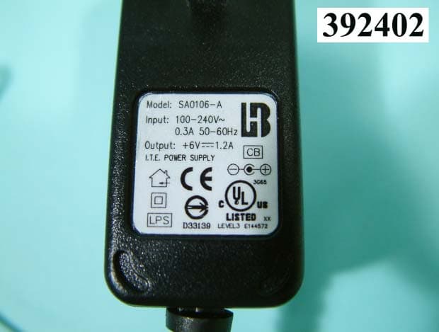
Click to zoom
Application Details
- Equipment Class
- DSS - Part 15 Spread Spectrum Transmitter
- Date of Grant
- Dec 07, 2003
- Application Purpose
- Original Equipment
- Date of Application
- Dec 07, 2003
- Equipment Note
- PRINTER ADAPTER02
- Frequency Range
- 2402.00000000 - 2480.00000000
- Company
- EPoX Computer Co., Ltd.
- Country
- Taiwan
Documents & Files
Document Text
Text extracted from the exhibit documents filed with the FCC. Open a document above to read the original.
Users Manual
EPoX USB PRINTER ADAPTER BT-PA02A ~ User’s Guide ~ DISCLAIMER OF WARRANTIES There are no warranties which extend beyond the description on the face of the EPoX limited warranty. EPoX expressly excludes all other warranties, express or implied, regarding its products; including any implied warranties of merchantability, fitness for a particular purpose or non-infringement. This disclaimer of warranties shall apply to the extend allowed by state laws in the states of United States in which state laws do not allow or limit the exclusion of the implied warranties. Document No : PA02AA0 REV 1.0 PA02AA0 REV 1.0 602A002P2A100 ~2~ USER’S GUIDE Thank you for purchasing an EPoX Bluetooth USB Printer Adapter! Your printer will soon be Bluetooth enabled, allowing you to print remotely from desktop PCs, notebook computers, PDAs, Pocket PCs and many other Bluetooth devices without any cables. A. ITEMS INCLUDED IN THIS PACKAGE 1 EPoX Bluetooth USB Printer Adapter 1 User Guide 1 AC/DC Power Adapter B.FEATURES & SPECIFICATION z Bluetooth Profile Supported: Serial Port z Printer Speed: Up to 115,200bps z Printer InterfaceUSB 1.1 compliant z Chipset: CSR BlueCore 02 z Buffer Memory: 32K Bytes SRAM z Power Consumption: 0.7 Watt, 6 Vdc z Power AdapterInput AC 100~240 Volts : Output DC 6V @ 1A z Frequency Range: 2.4-2.4835 GHz z Antenna: Build-In z Receive Sensitivity: From –80dBm to –85dBm z Range >100 meters (typical 300 Free space) z Operation System Supported Windows 98SE/ME/2000/XP PA02AA0 REV 1.0 602A002P2A100 ~3~ C. PRINTER ADAPTER HARDWARE INSTALLATION Plug the EPoX USB Printer adapter into the USB printer port of your printer as shown below. Now, your printer has become Bluetooth enabled. Congratulations!! 1.Plug BT-PA02A into the printer port. 2.Plug the power into the BT-PA02A "Note: Please do not use any other power adaptor with the EPoX USB Printer Adaptor (BT-PA02A). If you have problems, contact your dealer for a replacement. D. ESTABLISHING A CONNECTION To establish the Bluetooth connection, you have to configure the serial port setting on the Bluetooth device. If your Bluetooth device is an EPoX BT-MB02B or BT-DG02 or BT-DG03 or BT-DG02A, after the Widcomm protocol stack is installed, then follow the steps below. If your Bluetooth device is other than EPoX, please contact your manufacturer to obtain more information. D.1: Checking the COM port used by BT-PA02A EPoX Bluetooth USB Printer Adapter: PA02AA0 REV 1.0 602A002P2A100 ~4~ 1 Double click the Bluetooth icon to enter the My Bluetooth window. 2 By double-clicking on the Entire Bluetooth Neighborhood icon, you will find all the local Bluetooth enabled devices nearby. PA02AA0 REV 1.0 602A002P2A100 ~5~ 3 Find the EPoX BT-PA02A XXXXXX and double-click on it, the Cable Replacement icon be shown along with all the services offered by the printer adapter. 4 By double-clicking on the Cable Replacement icon, the “Cable Replacement” prompt window appears. It will show the COM port the EPoX Printer adapter will be using. Please make note of it and remember it. "Note: The COM port is automatic assigned and cannot be overridden. PA02AA0 REV 1.0 602A002P2A100 ~6~ D.2. Specifying the COM port on your printer: z If you haven’t installed the printer driver yet, please install it now. 1. By clicking the window Start button, select Setting and, then Printers, the printer setup window will display on the screen. 2. By double-clicking on the Add Printer icon, you will proceed with the printer driver installation for the Bluetooth enabled printer. PA02AA0 REV 1.0 602A002P2A100 ~7~ 3. Follow the installation steps to set up the printer. When choosing the printer port, please set the COM port as same as the BT-PA02A (Reference D.1 4). Windows 2000 Windows 98SE/ME Windows XP PA02AA0 REV 1.0 602A002P2A100 ~8~ z If your printer is already installed with its driver, please change the com port to the same BT-PA02A, and following the steps below: 1. By clicking the Start button, select Setting , and then click on Printers the printer setup window will be displayed. 2. Please select the printer connected to the BT-PA02A, and right-click on its icon, and then select Properties to enter the properties window. PA02AA0 REV 1.0 602A002P2A100 ~9~ 3. If your system is running Window 2000/XP, select the Ports tab. Choose the COM port that is being used by the BT-PA02A and press OK. You are done! If your system is running Window 98SE/ME, and select the Details tab. Choose the COM port that is being used by the BT-PA02A and press OK. You are done! PA02AA0 REV 1.0 602A002P2A100 ~10~ D.3: Important items to check Whether your printer drivers are installed or not, check the printer’s Properties (Please reference above). z If your system is running Window 2000/XP, and click on the Ports tab and check the following two items: 1. Uncheck Enable bidirectional support. 2. Click on the Configure Port. Button, then the COM X Properties prompt window will be shown and chose the 115200 port speed under the Bits per second drop down menu. PA02AA0 REV 1.0 602A002P2A100 ~11~ 3. Afterwards, click the OK button, which will take you back to the Properties prompt window, then click the Apply button and finally, click the OK button. z If your system is running Window 98SE/ME, and select the Details tab. 1. Click on the Spool Setting button, please select Disable bi-directional support for this printer and click on the OK button which will take you back to the Properties prompt window like above, and please go to the next step below. PA02AA0 REV 1.0 602A002P2A100 ~12~ 2. Click on the Port Setting.. button, and then the COM X Properties prompt window will be shown and chose 115200 port speed under the Bits per second drop down menu. 3. Afterwards, click the OK button, which will take you back to the Properties prompt window, then click the Apply button and finally, click the OK button. Congratulations!! You finish setting for BT-PA02A. PA02AA0 REV 1.0 602A002P2A100 ~13~ E.CONNECTIVITY This section wil…
Text truncated - open the document above for the full version.
External Photos
FCC ID: QLHCAE0303 Number 1 FRONT SIDE OF EUT FCC ID: QLHCAE0303 Number 2 REAR SIDE OF EUT FCC ID: QLHCAE0303 Number 3 FRONT SIDE OF ADAPTOR FCC ID: QLHCAE0303 Number 4 REAR SIDE OF ADAPTOR FCC ID: QLHCAE0303 Number 5 FRONT SIDE OF ADAPTOR
ID Label/Location Info
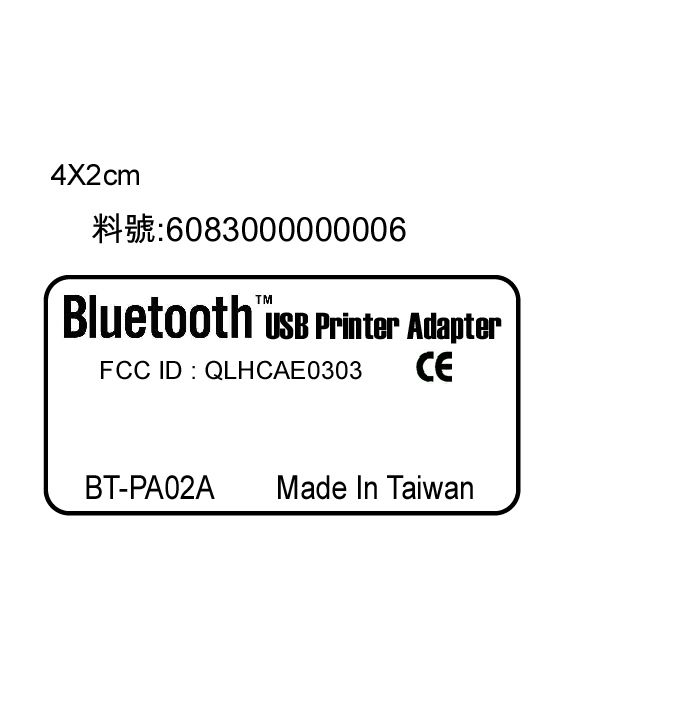
FCC ID: QLHCAE0303 Label Location
Internal Photos
FCC ID: QLHCAE0303 Number 1 MECHANICAL CONSTRUCTION FCC ID: QLHCAE0303 Number 2 MECHANICAL CONSTRUCTION FCC ID: QLHCAE0303 Number 3 FRONT SIDE MAIN BOARD FCC ID: QLHCAE0303 Number 4 CLOSER LOOK OF IC FCC ID: QLHCAE0303 Number 5 REAR SIDE MAIN BOARD FCC ID: QLHCAE0303 Number 6 CLOSER LOOK OF IC FCC ID: QLHCAE0303 Number 7 CLOSER LOOK OF IC
Test Report
FCC TEST REPORT Report No. : F392402 SPORTON International Inc. TEL : 886-2-2696-2468 FAX : 886-2-2696-2255 FCC TEST REPORT for 47 CFR, Part 15, Subpart C Equipment : Printer Adapter02 Model No. : BT-PA02A FCC ID. : QLHCAE0303 Filing Type : Certification Applicant : EPOX COMPUTER CO., LTD. 10F, 346, Sec. 2, Chung San Rd., Chung Ho City, Taipei Hsien, 235 Taiwan, R.O.C. The test result refers exclusively to the test presented test model / sample. Without written approval of SPORTON International Inc., the test report shall not be reproduced except in full. Certificate or Test Report must not be used by the applicant to claim the product in this test report endorsement by NVLAP or any agency of U.S. government. SPORTON International Inc. 6F, No.106, Sec. 1, Hsin Tai Wu Rd., Hsi Chih, Taipei Hsien, Taiwan, R.O.C. FCC TEST REPORT Report No. : F392402 SPORTON International Inc. FCC ID. : QLHCAE0303 TEL : 886-2-2696-2468 Page No. : i FAX : 886-2-2696-2255 Issued Date : Oct. 14, 2003 Table of Contents History of this test report..................................................................................................................ii CERTIFICATE OF COMPLIANCE........................................................................................................................1 1. General Description of Equipment under Test.............................................................................................2 1.1. Applicant..........................................................................................................................................................................................2 1.2. Manufacturer ...................................................................................................................................................................................2 1.3. Basic Description of Equipment under Test ....................................................................................................................................2 1.4. Feature of Equipment under Test ...................................................................................................................................................3 2. Test Configuration of Equipment under Test ...............................................................................................5 2.1. Test Manner ....................................................................................................................................................................................5 2.2. Description of Test System .............................................................................................................................................................5 2.3. Connection Diagram of Test System ..............................................................................................................................................7 3. Test Software ...................................................................................................................................................8 4. General Information of Test............................................................................................................................9 4.1. Test Voltage ....................................................................................................................................................................................9 4.2. Standard for Methods of Measurement...........................................................................................................................................9 4.3. Test in Compliance with ..................................................................................................................................................................9 4.4. Frequency Range Investigated .......................................................................................................................................................9 4.5. Test Distance ..................................................................................................................................................................................9 5. Report of Measurements and Examinations ..............................................................................................10 5.1. List of Measurements and Examinations ......................................................................................................................................10 5.2. Hopping Channel Separation ........................................................................................................................................................11 5.3. Number of Hopping Frequency .....................................................................................................................................................12 5.4. Hopping Channel Bandwidth.........................................................................................................................................................13 5.5. Dwell Time of Each Frequency within a 30 Seconds Period.........................................................................................................14 5.6. Output Power ................................................................................................................................................................................15 5.7. 100KHz Bandwidth of Frequency Band Edges .............................................................................................................................16 5.8. Test of Conducted Emission .........................................................................................................................................................17 5.9. Test of Radiated Emission ......................................................................................................................................................…
Text truncated - open the document above for the full version.
Test Report
FCC TEST REPORT Report No. : F392402 SPORTON International Inc. FCC ID. : QLHCAE0303 TEL : 886-2-2696-2468 Page No. : 1 of 15 FAX : 886-2-2696-2255 Issued Date : Oct. 14, 2003 1.1. Hopping Channel Separation Plot1(Channel 00) FCC TEST REPORT Report No. : F392402 SPORTON International Inc. FCC ID. : QLHCAE0303 TEL : 886-2-2696-2468 Page No. : 2 of 15 FAX : 886-2-2696-2255 Issued Date : Oct. 14, 2003 Plot2(Channel 39) FCC TEST REPORT Report No. : F392402 SPORTON International Inc. FCC ID. : QLHCAE0303 TEL : 886-2-2696-2468 Page No. : 3 of 15 FAX : 886-2-2696-2255 Issued Date : Oct. 14, 2003 Plot3(Channel 78) Comments6dB Emission bandwidth>500kHz FCC TEST REPORT Report No. : F392402 SPORTON International Inc. FCC ID. : QLHCAE0303 TEL : 886-2-2696-2468 Page No. : 4 of 15 FAX : 886-2-2696-2255 Issued Date : Oct. 14, 2003 1.2. Number of Hopping Frequency Plot1: FCC TEST REPORT Report No. : F392402 SPORTON International Inc. FCC ID. : QLHCAE0303 TEL : 886-2-2696-2468 Page No. : 5 of 15 FAX : 886-2-2696-2255 Issued Date : Oct. 14, 2003 1.3. Hopping Channel Bandwidth Plot1 (Channel 00) FCC TEST REPORT Report No. : F392402 SPORTON International Inc. FCC ID. : QLHCAE0303 TEL : 886-2-2696-2468 Page No. : 6 of 15 FAX : 886-2-2696-2255 Issued Date : Oct. 14, 2003 Plot2 (Channel 39) FCC TEST REPORT Report No. : F392402 SPORTON International Inc. FCC ID. : QLHCAE0303 TEL : 886-2-2696-2468 Page No. : 7 of 15 FAX : 886-2-2696-2255 Issued Date : Oct. 14, 2003 Plot3 (Channel 78) Comments All emissions in any 100kHz bandwidth outside the band edge are attenuated more then 20dB from the carrier. FCC TEST REPORT Report No. : F392402 SPORTON International Inc. FCC ID. : QLHCAE0303 TEL : 886-2-2696-2468 Page No. : 8 of 15 FAX : 886-2-2696-2255 Issued Date : Oct. 14, 2003 1.4. Dwell Time of Each Frequency within a 30 Seconds Period Plot1 (Channel 00) FCC TEST REPORT Report No. : F392402 SPORTON International Inc. FCC ID. : QLHCAE0303 TEL : 886-2-2696-2468 Page No. : 9 of 15 FAX : 886-2-2696-2255 Issued Date : Oct. 14, 2003 Plot2 (Channel 39) FCC TEST REPORT Report No. : F392402 SPORTON International Inc. FCC ID. : QLHCAE0303 TEL : 886-2-2696-2468 Page No. : 10 of 15 FAX : 886-2-2696-2255 Issued Date : Oct. 14, 2003 Plot3 (Channel 78) FCC TEST REPORT Report No. : F392402 SPORTON International Inc. FCC ID. : QLHCAE0303 TEL : 886-2-2696-2468 Page No. : 11 of 15 FAX : 886-2-2696-2255 Issued Date : Oct. 14, 2003 1.5. Output Power Plot1 (Channel 00) FCC TEST REPORT Report No. : F392402 SPORTON International Inc. FCC ID. : QLHCAE0303 TEL : 886-2-2696-2468 Page No. : 12 of 15 FAX : 886-2-2696-2255 Issued Date : Oct. 14, 2003 Plot2 (Channel 39) FCC TEST REPORT Report No. : F392402 SPORTON International Inc. FCC ID. : QLHCAE0303 TEL : 886-2-2696-2468 Page No. : 13 of 15 FAX : 886-2-2696-2255 Issued Date : Oct. 14, 2003 Plot3 (Channel 78) FCC TEST REPORT Report No. : F392402 SPORTON International Inc. FCC ID. : QLHCAE0303 TEL : 886-2-2696-2468 Page No. : 14 of 15 FAX : 886-2-2696-2255 Issued Date : Oct. 14, 2003 1.6. 100KHz Bandwidth of Frequency Band Edges Plot1 (Channel 00) FCC TEST REPORT Report No. : F392402 SPORTON International Inc. FCC ID. : QLHCAE0303 TEL : 886-2-2696-2468 Page No. : 15 of 15 FAX : 886-2-2696-2255 Issued Date : Oct. 14, 2003 Plot2 (Channel 78)
Test Setup Photos
FCC TEST REPORT Report No. : F392402 SPORTON International Inc. FCC ID : QLHCAE0303 TEL : 886-2-2696-2468 Page No. : 1 of 3 FAX : 886-2-2696-2255 Issued : Oct. 14, 2003 1.1. Photographs of Conducted Powerline Test Configuration z The photographs show the configuration that generates the maximum emission. FRONT VIEW REAR VIEW FCC TEST REPORT Report No. : F392402 SPORTON International Inc. FCC ID : QLHCAE0303 TEL : 886-2-2696-2468 Page No. : 2 of 3 FAX : 886-2-2696-2255 Issued : Oct. 14, 2003 SIDE VIEW FCC TEST REPORT Report No. : F392402 SPORTON International Inc. FCC ID : QLHCAE0303 TEL : 886-2-2696-2468 Page No. : 3 of 3 FAX : 886-2-2696-2255 Issued : Oct. 14, 2003 1.2. Photographs of Radiated Emission Test Configuration z The photographs show the configuration that generates the maximum emission. FRONT VIEW REAR VIEW
Contact Information
Applicant
Frank Tsai(Assistant Manager)
Test Firm
Sporton International Inc.Kathy Lin
Technical Specifications
| # | Rule Parts | Frequency Range | Power Output |
|---|---|---|---|
| 1 | 15C | 2.40 GHz - 2.48 GHz | 21.38 mW |
Other Applications from EPoX Computer Co., Ltd.
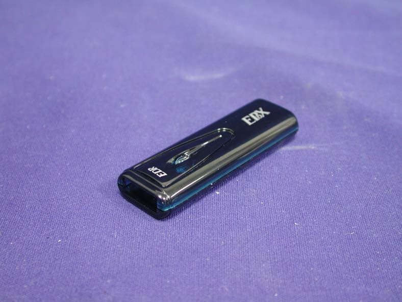
QLHCAT0305
Dec 26, 2005Bluetooth USB Dongle
Equipment Class
DSS - Part 15 Spread Spectrum Transmitter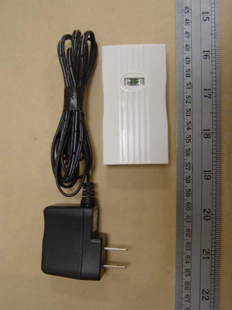
QLHCAR1104
Sep 28, 2005PRINTER ADAPTER
Equipment Class
DSS - Part 15 Spread Spectrum Transmitter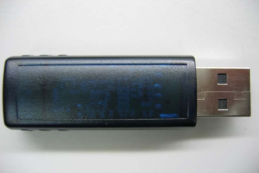
QLHCAQ0504
Jan 19, 2005Bluetooth USB Dongle
Equipment Class
DSS - Part 15 Spread Spectrum Transmitter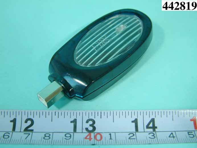
QLHCAN0304
Nov 21, 2004PRINTER ADAPTER
Equipment Class
DSS - Part 15 Spread Spectrum Transmitter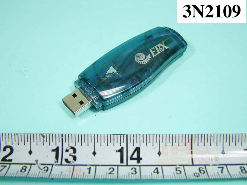
QLHCAI0803
Aug 18, 2004DONGLE
Equipment Class
DSS - Part 15 Spread Spectrum Transmitter