QLHCAF0303Presentation remote controller
EPoX Computer Co., Ltd.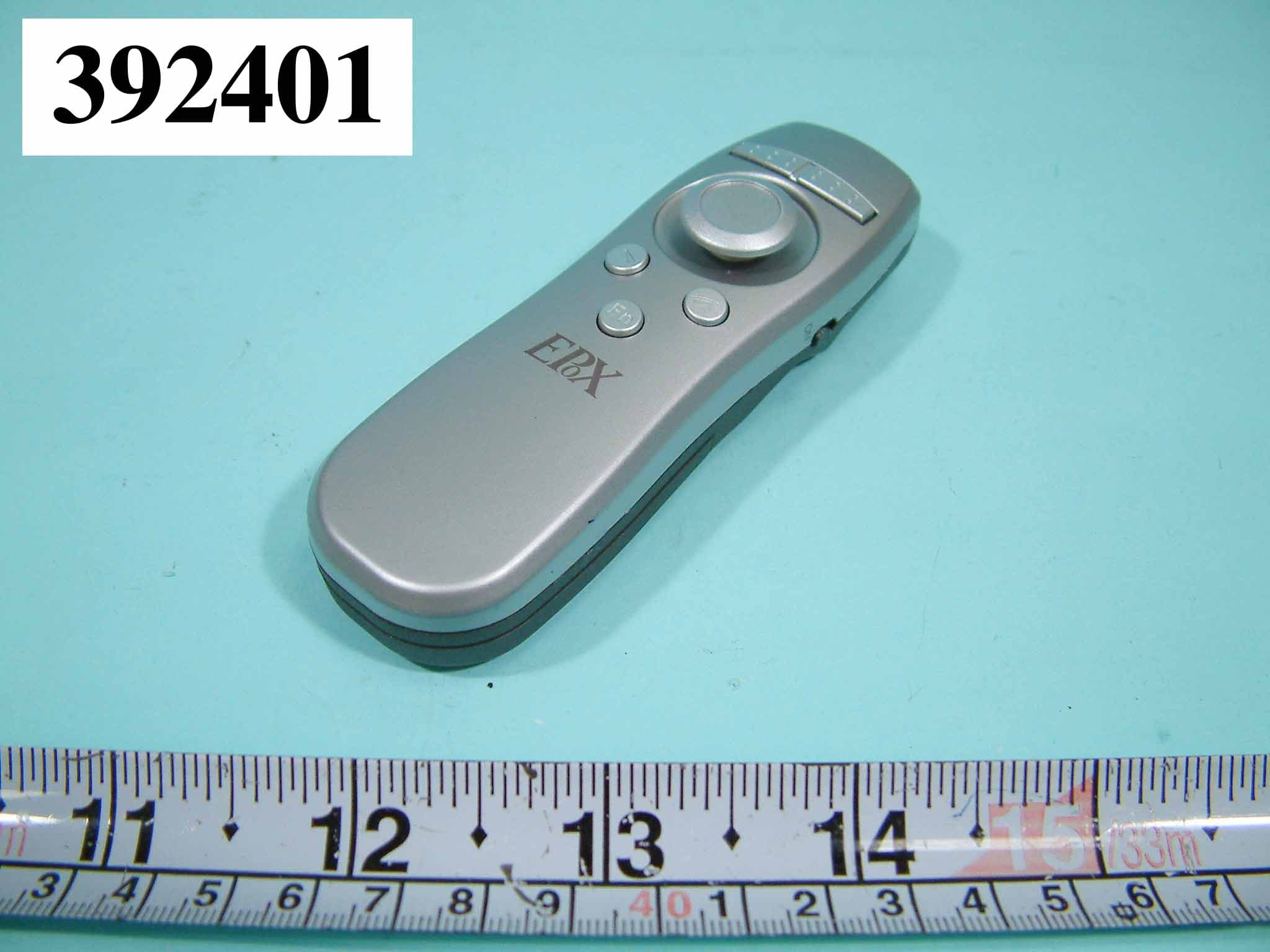
Click to zoom
Application Details
- Equipment Class
- DSS - Part 15 Spread Spectrum Transmitter
- Date of Grant
- May 06, 2004
- Application Purpose
- Original Equipment
- Date of Application
- May 06, 2004
- Equipment Note
- Presentation remote controller
- Frequency Range
- 2402.00000000 - 2480.00000000
- Company
- EPoX Computer Co., Ltd.
- Country
- Taiwan
Documents & Files
Document Text
Text extracted from the exhibit documents filed with the FCC. Open a document above to read the original.
Users Manual
EPoX Presenter BT-PM01B ~ User’s Guide ~ DISCLAIMER OF WARRANTIES There are no warranties which extend beyond the description on the face of the EPoX limited warranty. EPoX expressly excludes all other warranties, express or implied, regarding its products; including any implied warranties of merchantability, fitness for a particular purpose or non-infringement. This disclaimer of warranties shall apply to the extend allowed by state laws in the states of United States in which state laws do not allow or limit the exclusion of the implied warranties. Document No: PM01BA0 REV 1.0 PM01BA0 REV 1.0 602A002BPT100 ~2~ USER’S GUIDE Thank you for purchasing an EPoX Bluetooth Presenter (BT-PM01B)! Your Presenter will soon be Bluetooth enabled, allowing you to do presentation remotely from desktop PCs, notebooks, and let you can walk every where when you in the conference room. A. ITEMS INCLUDED IN THIS PACKAGE z EPoX Bluetooth Presenter (BT-PM01B) z User Guide z 2 * AAA Battery z CD of EPoX Bluetooth Presenter Application Software. B.FEATURES & SPECIFICATION z Chipset:CSR BlueCore 02 z Power Consumption : ~90mW @ 3 Vdc z power source:2 * AAA Battery z Frequency Range:2.4-2.4835 GHz z Antenna:Build-In z Antenna Load: 50 Ohm z Laser Module: Class II i. Power: Less than 1mW ii. Wavelength: 645~665nm iii. Color:Red light z Receive Sensitivity:–70dBm (typical) z TX Power:4dBm maximum ( class 2) z Range: >10 meters(line of sight) z Radio:Compliant with Bluetooth specification version 1.1 z Operating Channels:79 channels of 1MHz BW z Security:Full support of Bluetooth security provisions including hardware support for full length 128 bit encryption keys z Operation System Supported Windows 98SE/ME/2000/XP PM01BA0 REV 1.0 602A002BPT100 ~3~ C. PRESENTER HARDWARE INSTALLATION Before you using EPoX Presenter (BT-PM01B), please put in battery and turn on the power. Put Battery inside. Turn on power on Right button (Mouse right button) Left button (Mouse left button) Directional switch / Click (Mouse left button) Scroll down Scroll up Window change Power Switch PM01BA0 REV 1.0 602A002BPT100 ~4~ Laser Button Laser Definition of the function keys: 1. Right button: Be the same as mouse right button. 2. Left button: Same as mouse left button. 3. Directional switch: Similar to mouse track-ball, you can move the cursor through this switch. The function of clicking the switch is same as mouse left key. 4. Scroll up/down: When you doing the presentation with PowerPoint file, those keys are same as page up/down. You can change the page up or down for the PowerPoint file through those two keys. 5. Window change: This key is used to change the pop-out window of the file. Sometimes, several files might be required for the presentation. For the case, you can open those files in advance. During the presentation, you can choose which file to be displayed on the window through this key. 6. Laser Button: Laser beam is on by holding the laser button that is beneath the presenter. PM01BA0 REV 1.0 602A002BPT100 ~5~ D. ESTABLISHING A CONNECTION To establish the Bluetooth connection, you have to configure the serial port setting on the Bluetooth device. If your Bluetooth device is an EPoX BT-MB02 or BT-DG02 or BT-DG03, after the Widcomm protocol stack is installed, please follow the steps below. If your Bluetooth device is other than EPoX, please contact your manufacturer to obtain more information. D.1: Checking the COM port used by BT-PM01B Bluetooth Presenter: 1 Please turn on your Bluetooth Presenter (BT-PM01B) power. 2 Double click the Bluetooth icon to enter the “My Bluetooth” window. 3 By double-clicking on the “Entire Bluetooth Neighborhood” icon, you will find all the local Bluetooth enabled devices nearby. PM01BA0 REV 1.0 602A002BPT100 ~6~ 4 Find the EPoX BT-PM01B XXXXXX and double-click on it, the “Cable Replacement” icon be shown along with all the services offered by the Presenter. 5 By double-clicking on the “Cable Replacement” icon, the “Cable Replacement” prompt window appears. It will show the COM port the EPoX Bluetooth Presenter will be using. Please make note of it and remember it. "Note: The COM port is automatic assigned. If your COM port is occupied by another Bluetooth enabled device (For example: EPoX BT-PA01), you have to change COM port to connect with your Bluetooth Presenter (BT-PM01B). Please check F. TROUBLESHOOTING section 5 to setup other COM port. PM01BA0 REV 1.0 602A002BPT100 ~7~ D.2. Install Presenter (BT-PM01B) AP: z Please find out CD from EPoX Bluetooth Presenter (BT-PM01B) package. 1. Please put CD into your computer CD-ROM. 2. Run setup.exe for install EPoX Bluetooth Presenter (BT-PM01B) AP program. 3. Click next in Welcome dialog. 4. Click YES accept this agreement. PM01BA0 REV 1.0 602A002BPT100 ~8~ 5. After that, there will be an icon on your computers desktop area. Please click it. 6. You can find out another icon on system tray. Please move to there and click your mouse right button. PM01BA0 REV 1.0 602A002BPT100 ~9~ 7. Choose and click the “Setup Presenter”. 8. Setup your Presenter speed and COM port. 9. The default speed is set to 4. Which is also recommend. 10. Click OK to finish your Bluetooth Presenter (BT-PM01B) setup. Congratulations!! You have finished the setting for BT-PM01B &Note1: If your Bluetooth device is set to high security, the default PIN code is “0000”. &Note2: For power saving consideration, the BT-PM01B power will be automatically turned off for the following cases: 1. Once the power switch of BT-PM01B is turned-on, you have to establish the link to PC host within 5 minutes. Otherwise, the power of BT-PM01B will be automatically turned off. 2. If you do not use the BT-PM01B more than 2 hours, the BT-PM01B will be powered off. PM01BA0 REV 1.0 602A002BPT100 ~10~ Of course, you can re-establish the link by turning the power switch off and on again and then following the steps of section D. &Note3: The lever of directional switch is not designed to handle the strong ro…
Text truncated - open the document above for the full version.
Block Diagram
B B B l l l o o o c c c k k k D D D i i i a a a g g g r r r a a a m m m Bluetooth Bluetooth Bluetooth Bluetooth Module Module Module Module Power Power Power Power Converter Converter Converter Converter Keypad Keypad Keypad Keypad Laser Module Laser Module Laser Module Laser Module Battery Laser Diode Antenna Crystal 16MHz
External Photos
FCC ID: QLHCAF0303 Number 1 FRONT SIDE OF EUT FCC ID: QLHCAF0303 Number 2 REAR SIDE OF EUT
ID Label/Location Info
FCC ID: QLHCAF0303 SIZE: 10mm*20mm FCC ID : QLHCAF0303
Internal Photos
FCC ID: QLHCAF0303 Number 1 MECHANICAL CONSTRUCTION FCC ID: QLHCAF0303 Number 2 MECHANICAL CONSTRUCTION FCC ID: QLHCAF0303 Number 3 MECHANICAL CONSTRUCTION FCC ID: QLHCAF0303 Number 4 MECHANICAL CONSTRUCTION FCC ID: QLHCAF0303 Number 5 MECHANICAL CONSTRUCTION FCC ID: QLHCAF0303 Number 6 FRONT SIDE MAIN BOARD FCC ID: QLHCAF0303 Number 7 REAR SIDE MAIN BOARD FCC ID: QLHCAF0303 Number 8 CLOSER LOOK OF IC FCC ID: QLHCAF0303 Number 9 MECHANICAL CONSTRUCTION FCC ID: QLHCAF0303 Number 10 MECHANICAL CONSTRUCTION
Operational Description
FCC ID: QLHCAF0303 Operational Description 1. Bluetooth Module 1.1 RF Receiver The receiver features a near-zero Intermediate Frequency (IF) architecture that allows the channel filters to be integrated on to the die. Sufficient out-of –band blocking specification at the Low Noise Amplifier (LNA) input allows their radio to be used in close proximity to Global System for Mobile Communications (GSM) and Wideband Code Division Multiple Access (W-CDMA) cellular phone transmitters without being desensitized. The use of a digital Frequency Shift Keying (FSK) discriminator means that no discriminator tank is needed and its excellent performance in the presence of noise allows BlueCore2-External to exceed the Bluetooth requirements for co-channel and adjacent channel rejection. 1.1.1 Low Noise Amplifier The LNA can be configured to operate in single-External to exceed the Bluetooth requirements for co-channel and adjacent channel rejection. 1.1.2 Analogue to Digital Converter The Analogue to Digital Converter (ADC) is used to implement fast Automatic Gain Control (AGC). The ADC samples the Received Signal Strength Indicator (RSSI) voltage on a slot-by-slot basis. The front-end LNA gain is changed according to the measured RSSI value, keeping the first mixer input signal within a limited range. This improves the dynamic range of the receiver, improving performance in interference-limited environments. 1.2 RF Transmitter 1.2.1 IQ Modulator The transmitter features a direct IQ modulator to minimize the frequency drift during a transmit timeslot which results in a controlled modulation index. A digital base band transmit filter provides the required spectral shaping. 1.2.2 Power Amplifier The internal Power Amplifier (PA) has a maximum output power of +6dBm allowing BlueCore2-External to be used in Class 2 and Class 3 radios without an external RF PA. Support for transmit power control allows a simple implementation for Class 1 with an external RF PA. 1.3 RF synthesizer The radio synthesizer is fully integrated onto the die with no requirement for an external Voltage Controlled Oscillator (VCO) screening can, varactor tuning diodes or LC resonators. 1.4 Base band and Logic 1.4.1 Memory Management Unit The Memory Management Unit (MMU) provides a number of dynamically allocated ring buffers that hold the data, which is in transit between the host and the air or vice versa. The dynamic allocation of memory ensures efficient use of the available Random Access Memory (RAM) and is performed by hardware MMU to minimize the overheads on the processor during data/voice transfers. 1.4.2 Burst Mode Controller During radio transmission the Burst Mode Controller (BMC) constructs a packet form header information previously loaded into memory-mapped registers by the software and payload data/voice taken from the appropriate ring buffer in the RAM. During radio reception, the BMC stores the packet header in memory-mapped registers and the payload data in the appropriate ring buffer in RAM. This architecture minimizes the intervention required by the processor during transmission and reception. 1.4.3 Physical Layer Hardware Engine DSP Dedicated logic is used to perform the following: Forward error correction Header error control Cyclic redundancy check Encryption Data whitening Access code correlation Audio transcoding The following voice data translations and operations are performed by firmware: A-law/μ-law/linear voice date(from host) A-law/μ-law/Continuously Variable Slope Delta(CVSD)(over the air) Voice interpolation for lost packets Rate mismatches 1.4.4 RAM 32Kbytes of on-chip RAM is provided and is shared between the ring buffers used to hold voice/data for each active connection and the general purpose memory required by the Bluetooth stack. 1.4.5 External Memory Driver The External Memory Driver interface can be used to connect to the external Flash memory and also to the optional external RAM for memory intensive applications. 1.4.6 USB This is a full speed Universal Serial Bus interface for communicating with other compatible digital devices. BlueCore2-External acts as a USB peripheral, responding to requests form a Master host controller such as a PC. Physical Layer Hardware Engine DSP RAM Memory Mapped Control/ Status USB UART Audio PCM Interface Synchronous Serial Interface External Memory Driver Burst Mode Controller Memory Management Unit Programmable I/O RISC Micro-controller Interrupt Controller Event Timer Cloc k Generation Demodulator AUX DAC /N/N+1 RF Synthesizer VCD ADC IQ DEMOD LNA RF Receiver RSSI ADC RF Transmitter PA IQ MOD +45 -45 RF Synthesizer Fref Micro controller 2 Device Diagram PC Host Flash Memory I/O 3 Device Terminal Descriptions 3.1 RF Parts The BlueCore2-External RF_IN terminal can be configured as either a single-ended or differential input. The operational mode is determined by setting the Persistent Store Key PSKEY_TXRX_PIO_CONTROL (0x209). Using a single-ended RF input to be used for Class 2 operation, as shown in figure3.1. 2. Power Converter The Power Converter use TI TPS61016 DC/DC converter. Transfer voltage level form battery (AAA x 2) to stable DC 3.3V, supply BT-PM01B. 3. Keypad The keypad control of BT-PM01B functions, including Scroll-down, Scroll-up, function key and control of the cursor. 4. Laser Module The Laser Module support laser pointer function. Balun 1.8pF 1.8pF TS_A TX_B RF_IN BPF Figure 3.1: RF Parts (Class2)
Schematics
5 5 4 4 3 3 2 2 1 1 DD CC BB AA Power Supply PMS1 BT-PM01BM 1.0 Blue Tooth Presentation Point B 11Sunday, August 10, 2003 Title SizeDocument NumberRev Date:Sheet of RST LBO Laser SE SF SA SD SB SC SD LBO U_RX U_TX U_RX U_TX SF SE Interrupt Interrupt SG SPI_MOSI RST SPI_MISO SPI_CSB SPI_CLK SH SH SG SC SH SH SA SB SB SA SC SG SD SD VBATT 3V3 3V3 3V3 3V3 3V3 VCC VCC 3V3 R6 100k AN1 Antenna-2 pin 1 2 RF GD2 SW8 SW(DTSGL-61) 24 31 5 TP8GND R7 1M TP10 SW2-1 J4 CONNECTTOR 2P 2 1 2 1 C4 10uF C2 100pF TP11 SW2-2 RNI1 200K 1 2 3 4 5 6 7 8 RNI2 10K 12 34 56 78 R3 499k J2 CONNECTTOR 3P 2 1 3 2 1 3 TP12 SW3-2 C3 10uF SW4 SW(DTSGL-61) 24 31 5 TP3 1 J5 BTMODULE 2X4 2 4 6 8 1 3 5 7 910 TP2 1 TP1 1 TP13 SW8-2 D1 LASER/RED 12 J1 CONNECTTOR 3P 2 1 3 2 1 3 R8 NF C1 10uF L1 10uH R50 R1 0 C5 10nF & U3 7430 5 6 11 12 1 2 3 4 8 14 7 R4 499k SW2 SW(DTSGL-61) 24 31 5 J3 CONNECTTOR 3P 2 1 3 2 1 3 SW5 SW(DTSGL-61) 24 31 5 J6Battery Hloder(P) SW1 SW KEY-SK12D TP4 1 R9 NF TP5U_RX C63.3nH R2 200K TP6U_TX U2 TPS61016 7 6 9 8 3 14 2 10 5 SW VBAT LBI ADEN FB ENGND COMP LBO VOUT SW3 SW(DTSGL-61) 24 31 5 TP73V3 U1 CONNECTTOR 34P 16 7 12 10 13 8 18 9 21 14 19 11 20 31 30 29 28 27 26 25 24 17 34 1 32 33 22 23 6 5 4 15 2 3 +3V3 PIO(8) UART_TX PIO(11) UART_RTS PIO(9) PCM_OUT PIO(10) PCM_CLK UART_RX PCM_SYNC UART_CTS PCM_IN PIO(0) PIO(1) PIO(2) PIO(3) PIO(4) PIO(5) PIO(6) PIO(7) GND GND GND GND RF USB_DP USB_DN RESET AIO(1) AIO(0) +1V8 VDD_PA GND_PA J7Battery Hloder(N) 5 5 4 4 3 3 2 2 1 1 DD CC BB AA BT-PM01BS 1.0 Blue Tooth Presentation Point B 11Sunday, August 10, 2003 Title SizeDocument NumberRev Date:Sheet of SD SA SBSC SC SF SC SB SD SD SB SA Laser SA SE 3V3 3V3 J4 CONNECTTOR 2P 2 1 2 1 SW6 RKJXL C2 E F G H 21 D C B A C1 P1P2 J1 CONNECTTOR 3P 2 1 3 2 1 3 J3 CONNECTTOR 3P 2 1 3 2 1 3 SW7 SW(DTSGL-61) 24 31 5 J2 CONNECTTOR 3P 2 1 3 2 1 3 1 2 3 4 ABCD 4 3 2 1 D CBA Title Number Revision Size A4 Date: 13-Aug-2003 Sheet of File: C:\Net\371840006-1.ddb Drawn By: R1510R Z12.4V Q12N2222 Q22907 C20.1u +C14.7u VCC R21K D1PD VR1100K D2LD SMD,APC,3.1-4.5V 371840006
Test Report
FCC TEST REPORT Report No. : F392401 SPORTON International Inc. TEL : 886-2-2696-2468 FAX : 886-2-2696-2255 FCC TEST REPORT for 47 CFR, Part 15, Subpart C Equipment : Presentation Remote Controller01 Model No. : BT-PM01B FCC ID. : QLHCAF0303 Filing Type : Certification Applicant : EPOX COMPUTER CO., LTD. 10F, 346, Sec. 2, Chung San Rd., Chung Ho City, Taipei Hsien, 235 Taiwan, R.O.C. The test result refers exclusively to the test presented test model / sample. Without written approval of SPORTON International Inc., the test report shall not be reproduced except in full. Certificate or Test Report must not be used by the applicant to claim the product in this test report endorsement by NVLAP or any agency of U.S. government. Lab Code: 200079-0 SPORTON International Inc. 6F, No.106, Sec. 1, Hsin Tai Wu Rd., Hsi Chih, Taipei Hsien, Taiwan, R.O.C. FCC TEST REPORT Report No. : F392401 SPORTON International Inc. FCC ID. : QLHCAF0303 TEL : 886-2-2696-2468 Page No. : i FAX : 886-2-2696-2255 Issued Date : May 6, 2004 Table of Contents History of this test report..................................................................................................................ii CERTIFICATE OF COMPLIANCE........................................................................................................................1 1. General Description of Equipment under Test.............................................................................................2 1.1. Applicant..........................................................................................................................................................................................2 1.2. Manufacturer ...................................................................................................................................................................................2 1.3. Basic Description of Equipment under Test ....................................................................................................................................2 1.4. Feature of Equipment under Test ...................................................................................................................................................2 2. Test Configuration of Equipment under Test ...............................................................................................4 2.1. Test Manner ....................................................................................................................................................................................4 2.2. Description of Supporting Units.......................................................................................................................................................4 2.3. Connection Diagram of Test System ..............................................................................................................................................6 3. Test Software ...................................................................................................................................................7 4. General Information of Test............................................................................................................................8 4.1. Test Voltage ....................................................................................................................................................................................8 4.2. Standard for Methods of Measurement...........................................................................................................................................8 4.3. Test in Compliance with ..................................................................................................................................................................8 4.4. Frequency Range Investigated .......................................................................................................................................................8 4.5. Test Distance ..................................................................................................................................................................................8 5. Report of Measurements and Examinations ................................................................................................9 5.1. List of Measurements and Examinations ........................................................................................................................................9 5.2. Hopping Channel Separation ........................................................................................................................................................10 5.3. Number of Hopping Frequency .....................................................................................................................................................11 5.4. Hopping Channel Bandwidth.........................................................................................................................................................12 5.5. Dwell Time of Each Frequency within a 30 Seconds Period.........................................................................................................13 5.6. Output Power ................................................................................................................................................................................14 5.7. 100KHz Bandwidth of Frequency Band Edges .............................................................................................................................15 5.8. Test of Conducted Emission .........................................................................................................................................................16 5.9. Test of Radiated Emission ............................................................................................................................…
Text truncated - open the document above for the full version.
Test Report
FCC TEST REPORT Report No. : F392401 SPORTON International Inc. FCC ID. : QLHCAF0303 TEL : 886-2-2696-2468 Page No. : 1 of 1 FAX : 886-2-2696-2255 Issued Date : Oct. 16, 2003 1.1. Hopping Channel Separation Plot1(Channel 00): APPENDIX PLOT FCC TEST REPORT Report No. : F392401 SPORTON International Inc. FCC ID. : QLHCAF0303 TEL : 886-2-2696-2468 Page No. : 2 of 2 FAX : 886-2-2696-2255 Issued Date : Oct. 16, 2003 Plot2(Channel 39): FCC TEST REPORT Report No. : F392401 SPORTON International Inc. FCC ID. : QLHCAF0303 TEL : 886-2-2696-2468 Page No. : 3 of 3 FAX : 886-2-2696-2255 Issued Date : Oct. 16, 2003 Plot3(Channel 78): Comments:6dB Emission bandwidth>500kHz FCC TEST REPORT Report No. : F392401 SPORTON International Inc. FCC ID. : QLHCAF0303 TEL : 886-2-2696-2468 Page No. : 4 of 4 FAX : 886-2-2696-2255 Issued Date : Oct. 16, 2003 1.2. Number of Hopping Frequency Plot1: FCC TEST REPORT Report No. : F392401 SPORTON International Inc. FCC ID. : QLHCAF0303 TEL : 886-2-2696-2468 Page No. : 5 of 5 FAX : 886-2-2696-2255 Issued Date : Oct. 16, 2003 1.3. Hopping Channel Bandwidth Plot1 (Channel 00): FCC TEST REPORT Report No. : F392401 SPORTON International Inc. FCC ID. : QLHCAF0303 TEL : 886-2-2696-2468 Page No. : 6 of 6 FAX : 886-2-2696-2255 Issued Date : Oct. 16, 2003 Plot2 (Channel 39): FCC TEST REPORT Report No. : F392401 SPORTON International Inc. FCC ID. : QLHCAF0303 TEL : 886-2-2696-2468 Page No. : 7 of 7 FAX : 886-2-2696-2255 Issued Date : Oct. 16, 2003 Plot3 (Channel 78): Comments: All emissions in any 100kHz bandwidth outside the band edge are attenuated more then 20dB from the carrier. FCC TEST REPORT Report No. : F392401 SPORTON International Inc. FCC ID. : QLHCAF0303 TEL : 886-2-2696-2468 Page No. : 8 of 8 FAX : 886-2-2696-2255 Issued Date : Oct. 16, 2003 1.4. Dwell Time of Each Frequency within a 30 Seconds Period Plot1 (Channel 00): FCC TEST REPORT Report No. : F392401 SPORTON International Inc. FCC ID. : QLHCAF0303 TEL : 886-2-2696-2468 Page No. : 9 of 9 FAX : 886-2-2696-2255 Issued Date : Oct. 16, 2003 Plot2 (Channel 39): FCC TEST REPORT Report No. : F392401 SPORTON International Inc. FCC ID. : QLHCAF0303 TEL : 886-2-2696-2468 Page No. : 10 of 10 FAX : 886-2-2696-2255 Issued Date : Oct. 16, 2003 Plot3 (Channel 78): FCC TEST REPORT Report No. : F392401 SPORTON International Inc. FCC ID. : QLHCAF0303 TEL : 886-2-2696-2468 Page No. : 11 of 11 FAX : 886-2-2696-2255 Issued Date : Oct. 16, 2003 1.5. Output Power Plot1 (Channel 00): FCC TEST REPORT Report No. : F392401 SPORTON International Inc. FCC ID. : QLHCAF0303 TEL : 886-2-2696-2468 Page No. : 12 of 12 FAX : 886-2-2696-2255 Issued Date : Oct. 16, 2003 Plot2 (Channel 39): FCC TEST REPORT Report No. : F392401 SPORTON International Inc. FCC ID. : QLHCAF0303 TEL : 886-2-2696-2468 Page No. : 13 of 13 FAX : 886-2-2696-2255 Issued Date : Oct. 16, 2003 Plot3 (Channel 78): FCC TEST REPORT Report No. : F392401 SPORTON International Inc. FCC ID. : QLHCAF0303 TEL : 886-2-2696-2468 Page No. : 14 of 14 FAX : 886-2-2696-2255 Issued Date : Oct. 16, 2003 1.6. 100KHz Bandwidth of Frequency Band Edges Plot1 (Channel 00): FCC TEST REPORT Report No. : F392401 SPORTON International Inc. FCC ID. : QLHCAF0303 TEL : 886-2-2696-2468 Page No. : 15 of 15 FAX : 886-2-2696-2255 Issued Date : Oct. 16, 2003 Plot2 (Channel 78):
Test Setup Photos
FCC TEST REPORT Report No. : F392401 SPORTON International Inc. FCC ID : QLHCAF0303 TEL : 886-2-2696-2468 Page No. : 1 of 1 FAX : 886-2-2696-2255 Issued : Oct. 16, 2003 1.1. Photographs of Radiated Emission Test Configuration z The photographs show the configuration that generates the maximum emission. FRONT VIEW REAR VIEW
Contact Information
Applicant
Frank Tsai(Assistant Manager)
Test Firm
Sporton International Inc.Kathy Lin
Technical Specifications
| # | Rule Parts | Frequency Range | Power Output |
|---|---|---|---|
| 1 | 15C | 2.40 GHz - 2.48 GHz | 690.00 µW |
Other Applications from EPoX Computer Co., Ltd.
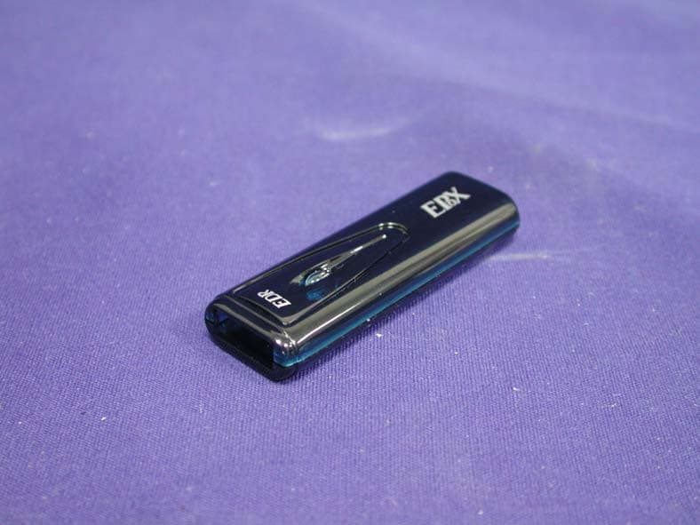
QLHCAT0305
Dec 26, 2005Bluetooth USB Dongle
Equipment Class
DSS - Part 15 Spread Spectrum Transmitter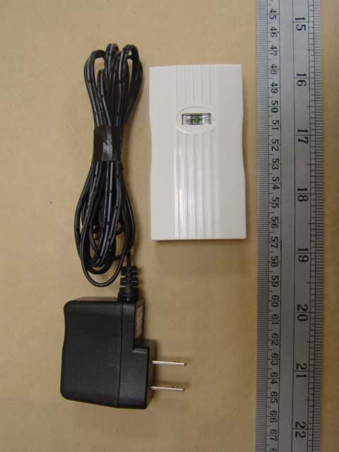
QLHCAR1104
Sep 28, 2005PRINTER ADAPTER
Equipment Class
DSS - Part 15 Spread Spectrum Transmitter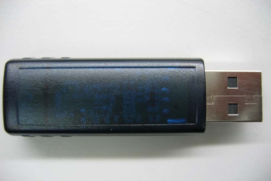
QLHCAQ0504
Jan 19, 2005Bluetooth USB Dongle
Equipment Class
DSS - Part 15 Spread Spectrum Transmitter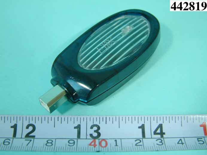
QLHCAN0304
Nov 21, 2004PRINTER ADAPTER
Equipment Class
DSS - Part 15 Spread Spectrum Transmitter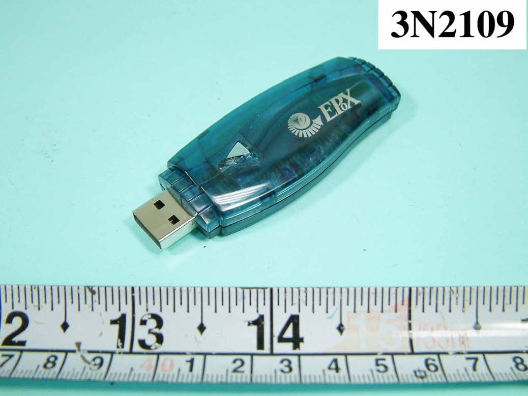
QLHCAI0803
Aug 18, 2004DONGLE
Equipment Class
DSS - Part 15 Spread Spectrum Transmitter