QN35800MSECURITY WIRELESS WINDOW SENSOR
Ion Digital LLP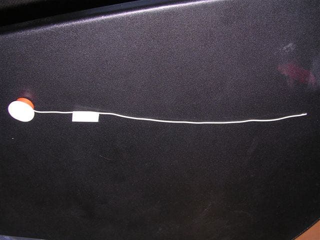
Click to zoom
Application Details
- Equipment Class
- DSC - Part 15 Security/Remote Control Transmitter
- Date of Grant
- Oct 05, 2004
- Application Purpose
- Original Equipment
- Date of Application
- Oct 05, 2004
- Equipment Note
- SECURITY WIRELESS WINDOW SENSOR
- Frequency Range
- 345.00000000 - 345.00000000
- Company
- Ion Digital LLP
- Country
- United States
Documents & Files
Document Text
Text extracted from the exhibit documents filed with the FCC. Open a document above to read the original.
Users Manual
Sash Magnet Press the iON 5800 MICRA transmitter's corresponding magnet into the cavity now drilled into the sash, making sure to position the iON icons to point in the same direction. NOTE: This point is essential to the systems proper operation. Measure 3" down from the inside top corner of the mainframe and mark the center point for the hole the iON 5800 MICRA transmitter will be inserted into. Place a corresponding mark also on the sash insert that will be used in this position. Measure & Drill 1 2 Place and Set NOTE: It is essential to the systems operation that the positioning of the iON icon on the transmitter point in the same direction as its corresponding sash magnet. Insert the iON 5800 MICRA's antenna into the extrusion hollow then press the transmitter body into the cored opening. Using a 3/4" Forstner Drill Bit, drill into the vinyl window mainframe. Sash Magnet Placement 3 NOTE: The vinyl extrusion should be pre-qualified by a iON Security rep. to ensure the frame will accommodate the iON 5800 MICRA transmitter as well as the placement of its corresponding magnet. Side mount transmitter on Vinyl Sliders Sill mount transmitter on Hung Windows Horizonta l Slidi ng Sash Vertical Sliding Sash Using a 3/4" Forstner Drill Bit, drill into the window sash to a depth of 1/3" only. 0.5" < extrusion hollow > 0.33" core depth outer wall of window frame inner wall of window frame 3/4" Forstner drill bit iON 5800 MICRA Recessed Transmitter Installation Instructions For use with QED control panels ONLY! GENERAL INFORMATION The iON 5800 MICRA recessed transmitter is a reed switch magnetic contact transmitter that provides concealed protection for a window. It is intended for use only with alarm systems that support QED 5800 series devices. The transmitter is powered by a long-life lithium battery that is easily replaceable when a low battery is indicated by the control. Programming the ID Number Each iON 5800 MICRA has its own unique identification code (serial number) permanently assigned during manufacturing. The control unit is required to "enroll" the transmitter's ID during installation of the alarm system. The iON 5800 MICRA response should be enrolled as "RF" (i.e. Supervised RF) Type (mandatory for all UL installations). Refer to the QED control unit's installation instructions for further details. PRELIMINARY CONSlDERATlONS Read all of this and the next section before installing the unit. 1. Select a location for the transmitter on the frame of the window. Do not use on metal frame doors or windows. iON 5800 MICRA TRANSMITTER The iON 5800 MICRA transmitter will require a 3/4" diameter hole (using a 3/4" Forstner bit) drilled into the edge of the window frame no more than 1/3" deep. Its accompanying magnet will need a 3/4" diameter hole drilled in the side of the window sash, no more than 1/3" deep. BEFORE DRlLLlNG ANY HOLES, SEE ITEM 2 BELOW AND MOUNTlNG SECTION ON THE NEXT PAGE. FOR VINYL SLIDING WINDOWS the preferred direction of mounting is vertical. FOR HUNG WINDOWS the iON 5800 MICRA must be mounted horizontally in the window sill with the accompanying magnet mounted in the lower window sash. (see Step 1 - Measure & Drill in Figure 1) 2. Before drilling any holes, tape the transmitter and magnet in their approximate locations (with battery installed and unit together as described under BATTERY INSTALLATION / REPLACEMENT (see page back) and conduct Go/No Go tests (see QED control's instructions) to verify adequate signal strength. Reorient or relocate the transmitter if necessary. Make sure that no more than a 1/2" gap will be present between the faces of the transmitter and magnet cases when they are installed and set. Also make sure the 'iON' graphic on the transmitter and magnet are aligned with each other as per Step 3 - Sash Magnet Placement in Figure 1. When installed, an alarm signal must be obtained before a clear space of 2" is reached as the window is opened. Under no circumstances should the outer wall of the window frame be penetrated by the Forstner bit. Figure 1 WARNING: under no circumstances should the outer wall of the window frame be penetrated by the Forstner bit. www.ion-digital.com THE SENSE OF SECURITY ™ SPECIFICATIONS iON 5800 MICRA transmitters Dimensions Dowel Package 0.750" diameter Additional Info Dowel Lid 0.850" diameter x 0.060" thick Wire Antenna 11" x 0.050" diameter (24 gauge) Fits Cavity Depth 0.330" depth Power Source 3.0V Lithium Coin Cell Battery CR1620 Transmit Range Typically >500 ft. open air Temperature Range 10º to 120º F (-12º to 49º C) Compatibility Windows All Vinyl Window Types, Wood Casement, Awning, Double-Hung and Access. MOUNTING (See Figure 1) 1. Mark the selected location for the transmitter on the frame of the window. 2. Mark the location for the magnet on the window sash, directly opposite the transmitter location. Before drilling any holes, make sure that the successful Go/No Go transmission receptin tests have been conducted as called for in the iON 5800 MICRA transmitter section. (see page back) 3. Drill holes at the locations marked, for the transmitter (3/4" diameter, no more than 1/3" deep) and magnet (3/4" diameter, no more than 1/3" deep using a 3/4 Forstner bit). 4. lnsert the transmitter and magnet cases into their respective holes so that their caps are flush with the surface. Make sure the antenna goes into the cavity as straight as possible. DO NOT hammer the transmitter or the magnet in place with hard blows. Press them into their respective holes by hand. The iON 5800 MICRA uses a santaprene case that, once placed, is designed to self-seal in the mounting hole. However, if desired, a thin bead of silicon may be applied for additional moisture protection. iON 5800 MICRA Recessed Transmitter TO THE INSTALLER Regular maintenance and inspection (at least annually) by the installer and frequent testing by the user are vital to continuous satisfactory operation of any alarm system. The installer should assume the …
Text truncated - open the document above for the full version.
Cover Letter(s)
September 28, 2004 Federal Communications Commission Authorization and Evaluation Division Confidentiality Request FCC ID: QN35800M Pursuant to Sections 0.457 and 0.459 of the Commissions Rules, the Applicant hereby requests confidential treatment of information accompanying this Application as outlined below: Schematics Block Diagram & Operation Descriptions Bill of Materials The above materials contain trade secrets and proprietary information not customarily released to the public. The public disclosure of these matters might be harmful to the Applicant, and provide unjustified benefits to it’s competitors. Sincerely, Dean Schebel Director - Engineering ION DIGITAL LLP ION DIGITAL LLP• PO BOX 3969 • BLAINE WA, USA 98231 PHONE: 1-800-407-4389 • FAX: 1-800-407-4465
Schematics
1 2 3 4 56 ABCD 6 5 4 3 2 1 D CBA 1 I ON D ig i ta l LL PPO Bo x 4 5 5 5 9Surrey, BC CanadaV4 A 9 N 3 1 580 0 MICRA 100 11-Sep-2004 12:27:44 MIC RA.SC H Titl eSize: Dat e: File: Rev : Sheet of Time: B ION 5800 MICRA E r ro r : lo g o000.bm p fil e File and Path: S:\d eans\Ad emco Project Sept 2 200 3\MICRA WINDOW\REV 100\ION 580 0 MICRA REV 10 0.d db - Documents\MICRA.SCH VC C S1UM23 19 BATTERY MICROP ROCESSOR R3100 K 0.5% R433K 0.5% R2100 K TP DT R TP TP TES T/R TSTP C1100 N C3 220 P R7100 K C5100 N L133N RF TRANSMITTER ANTENNA CM382P TP TD ITP TP TMSTP VC C CM210P BA TTER Y M ON ITO R CM110P No te s : AN T_ O UT Length = 1 1.5 " 24gauge Y332.768KHz TP TD OTP TP TC KTP Y410.7812 5MHz RT11K0 C447p Vs s 1 ic 2 OS C IN 3 OS C O UT 4 VD D 7 MOT1 8 MOT2 9 RESET 10 nc 5 nc 6 U1 0 PC A2 0 0 2 HK AS KD at a 1 FSKData 2 FSKsw 3 RO I 4 EN TX 5 PSE L 6 VE E 7 OU T 8 VE E 9 VC C 10 GND 11 GND 12 GND 13 GND 14 U1 1TH72005 LM147N TP RESTP R5100 K R6100 K LV 1390 N LV 2390 N Batt+ Batt- Batt+ DA TAEN TX No te : Th e b at tery i n s erte din the hold er adds 3 .0pFto g nd, resu lting in a net 13 pFvalue for CM2 TES T 22 VC C 23 P2.5/Rosc 24 VS S 2 XO UT 3 XIN 4 RS T/N MI 5 P2.0/AC LK 6 P2.1/INCLK 7 P2.2/CAOUT/TA0 8 P2.3/CA0/TA1 10 P2.4/CA1/TA2 11 P1.0/TAC LK 13 P1.1/TA0 14 P1.2/TA1 15 P1.3/TA2 16 P1.4/SMCLK/TC K 17 P1.5/TA0/TMS 18 P1.6/TA1/TDI 20 P1.7/TA2/TDO/TDI 21 NC 9 NC 1 NC 12 NC 19 U3MSP430 F1101RGE R110K C21U TP MOT2TP Batt- 1 Batt- 2 J2WD_NC Batt+ 1 Batt+ 2 Batt+ 3 Batt+ 4 J1WD_PC4 R81M
Test Report
EMC Compatibility Testing Report Rev. 1.0 ION Digital LLP – ION 5800 Micra Report Number: 03023Page 1 of 13 ION Digital LLP ION 5800 MICRA Report of Measurements per FCC CFR47 Part 15/C REVISION 0.2 September 28, 2004 Approved by Checked by Robert Stirling, P.Eng.Date Protocol Labs, Abbotsford BC, Canada FCC Registration Number 96437 Industry Canada Registration Number IC3384 EMC Compatibility Testing Report Rev. 1.0 ION Digital LLP – ION 5800 Micra Report Number: 03023Page 2 of 13 Index Section I:FCC CFR47 Part 15/C Report of Measurements................................................................ 3 Section Ia: FCC CFR47 Part 15/C Report of Measurements.............................................. 4 Part 1 - Radiated Emission Testing ..................................................................................... 5 Appendix A:Photos ................................................................................................................................. 6 Appendix B:Measurement Data and Plots .............................................................................................. 8 Spurious Emissions Plot...................................................................................................... 9 Appendix C:ION DIGITAL LLP 5800 MICRA ........................................................................................ 11 Timing Plots....................................................................................................................... 12 EMC Compatibility Testing Report Rev. 1.0 ION Digital LLP – ION 5800 Micra Report Number: 03023Page 3 of 13 Section I: FCC CFR47 Part 15/C Report of Measurements Testing Details TESTED BY: David Johanson TEST CONDITIONS:Temperature and Humidity: 10.5 ° C 67% TEST VOLTAGE:3 Vdc - Lithium Battery Test Facilities Protocol Labs 28945 McTavish Rd. Abbotsford BC, Canada, V4X 2E7 FCC Registration Number 96437 Industry Canada Registration Number IC3384 Test Equipment List EMISSIONS: DeviceModel NumberSerial No.Last Cal. Next Cal AntennaEMCO 31159403-425115/10/0315/10/04 AntennaEMCO 3141 Bilog112727/10/0327/10/04 Spectrum Analyzer Hewlett Packard 8566B2241A0210214/11/0314/11/04 RF-Preselector Hewlett Packard 85685A 3107A0122210/01/0410/01/05 Quasi-Peak Adapter Hewlett Packard 85650A 2043A0024010/01/0410/01/05 TowerRhientech LabsCustomN/AN/A TurntableProtocolCustomN/AN/A Company Under Test: NAME:ION Digital LLP USA Office ION Digital LLP Canada Office ADDRESS:PO Box 3969#3-3033 King George Hwy. Blaine WA, USA 98231Surrey BC, Canada, V4P 1B8 CONTACT PERSON:Mr. Dean Schebel Director – Engineering [email protected] PHONE NUMBER:800-407-4389 FAX NUMBER:800-407-4465 Equipment Under Test: THE TEST SYSTEM:EUT 1:Wireless Window Sensor Manufacturer:Ion Digital LLP Model Number:ION 5800 MICRA Serial Number:EN6001 TEST SETUP:The EUT was setup in its normal operating mode. MODIFICATIONS: This unit requires no modifications for it to pass. CONCLUSION: The ION 5800 MICRA that was tested complies with the requirements of FCC CFR47 part 15/B and C. EMC Compatibility Testing Report Rev. 1.0 ION Digital LLP – ION 5800 Micra Report Number: 03023Page 4 of 13 Section Ia: FCC CFR47 Part 15/C Report of Measurements General Tests were conducted on a sample of the equipment for the purpose of demonstrating compliance with FCC Part 15/C – Intentional Radiators The Radiated tests were performed using measurement procedure outlined in the above standard. FCC Labeling and Marking Requirements: Markings According to FCC Section 15.19, a statement similar to the following must be included on an identification label, which also uniquely identifies the Manufactured date, either explicitly or through a Serial number etc.: "This equipment complies with FCC Rules, Part 15 for an Intentional Radiator. Operation is subject to two conditions: 1) This device may not cause harmful interference 2) This device must accept any interference that may cause any undesired operation" Labeling According to FCC Section 15.19 labeling requirements the following statement must be included in a prominent location in your User's Manual: This device complies with Part 15 of the FCC Rules; Operation is subject to the condition that this device not cause harmful interference Caution: Changes or modifications to this equipment, not expressly approved by the manufacturer could void the user's authority to operate the equipment. EMC Compatibility Testing Report Rev. 1.0 ION Digital LLP – ION 5800 Micra Report Number: 03023Page 5 of 13 Part 1 - Radiated Emission Testing DATE:September 17, 2004 TEST STANDARD:FCC CFR47, Part 15, Subpart C 15.231 RADIATED SETUP:The equipment was set up in an open field test site. All spurious and harmonic measurements were made at a 3-meter open field test site. Peak spurious Emissions in both horizontal and vertical polarization’s were measured based on continuous modulated signal while rotating the EUT on a turntable to maximize the emissions signal strength and the results recorded on the attached tables and plots. Average emissions are based on actual duty cycles pulsed and modulated signal as in Appendix C. MINIMUM STANDARD: Fundamental Frequency Field Strength of FundamentalField Strength of Spurious Emissions Measurement Distance (MHz) ( μ μμ μ V)(dB μ μμ μ V) ( μ μμ μ V)(dB μ μμ μ V) 40.66 – 40.702,25067.022547.0 70 -1301,25061.912541.9 130 -1741,250 to 3,750**61.9 –71.5125 to 375**41.9 – 51.5 174 - 2603,75071.537551.5 260 - 4703,750 to 12,500**71.5 – 81.9375 to 1,250**51.5 – 61.9 Above 47012,50081.91,25061.9 For this EUT 340 7294.5877.26729.4657.260 **Linear interpolations DEVICE DESCRIPTIONS:Refer to the Equipment Under Test Section, above, for EUT Descriptions. PHOTOS:See Appendix A MEASUREMENT DATA: See Appendix B for Plot EMISSIONS DATA: See Table 1 in Appendix B for corresponding frequencies. PERFORMANCE:Complies. EMC Compatibility Testing Report Rev. 1.0 ION Digital LLP – ION 5800 Micra Report Number: 03023Page 6 of…
Text truncated - open the document above for the full version.
Test Setup Photos
EMC Compatibility Testing Report Rev. 1.0 ION Digital LLP – ION 5800 Micra Report Number: 03023Page 6 of 13 Appendix A: Photos Emissions Test Setup for EUT Close up EMC Compatibility Testing Report Rev. 1.0 ION Digital LLP – ION 5800 Micra Report Number: 03023Page 7 of 13 Emissions Test Setup for EUT Holder Button Sensor Antenna
Contact Information
Applicant
Dean Schebel(RF Design Engineer)
Test Firm
Protocol LabsRobert Stirling
Technical Specifications
| # | Rule Parts | Frequency Range | Power Output |
|---|---|---|---|
| 1 | 15.231 | 345 MHz - 345 MHz | - |
Other Applications from Ion Digital LLP
QN35800XT
Feb 05, 2012SECURITY DEVICE/ALARM SYSTEM RECESSED TRANSMITTER
Equipment Class
DSC - Part 15 Security/Remote Control Transmitter
QN3WD01
Nov 04, 2002Security/Remote Control Transmitter
Equipment Class
DSC - Part 15 Security/Remote Control Transmitter
QN3FP01
Nov 04, 2002Security/Remote Control Transmitter
Equipment Class
DSC - Part 15 Security/Remote Control Transmitter