QN3FP01Security/Remote Control Transmitter
Ion Digital LLP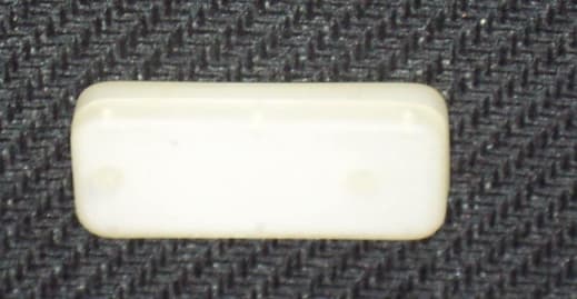
Click to zoom
Application Details
- Equipment Class
- DSC - Part 15 Security/Remote Control Transmitter
- Date of Grant
- Nov 04, 2002
- Application Purpose
- Original Equipment
- Date of Application
- Nov 04, 2002
- Equipment Note
- Security/Remote Control Transmitter
- Frequency Range
- 433.92000000 - 433.92000000
- Company
- Ion Digital LLP
- Country
- United States
Documents & Files
Document Text
Text extracted from the exhibit documents filed with the FCC. Open a document above to read the original.
Users Manual
FCC ID: QN3FP01Installation Guide ION Digital LLP11/04/02 1 of 5 ION Digital LLPPh# 1-800-407-4389 P.O. Box 3969 Blaine WashingtonFax# 1-800-407-4465 USA 98231www.ion-digital.com Exterior Window / Door Security Sensor Installation Instructions The Exterior Window / Door Sensor/Transmitter detects when a window is closed or opened, and transmits a wireless security message to the System Control Panel. This is accomplished through the use of a sensor unit (which contains the wireless transmitter and battery), and magnet unit. When the two are separated, by opening the window, the sensor transmits an OPEN signal to the System Control Panel. When the window is shut, the magnet is again within the sensor's range, and a CLOSE signal is sent. Fig 1: Sensor and Magnet SensorMagnet The sensor sends supervisory signals to the panel every 64 minutes (approximately). The sensor is powered by a 3.0V, lithium battery, model CR2032. Required Tools for Installation Installation Sheet for documenting sensor locations Screwdriver (if mounting using screws instead of adhesive) Guidelines The following guidelines will help ensure that installations are safe and efficient. A sensor can be mounted on any side of the window frame (top, side or bottom), such that the opening of the window moves the magnet away from the sensor. Always try to mount the hardware such that the magnet, not the sensor, is on the moving window panel. The sensor can be installed on the moving window panel, but should be avoided. The device can be mounted on a metal frame, however range will decrease slightly. Do not install the sensor on the frame until confirming the panel can detect the sensor. The sensor should be kept as close to the panel or repeater as possible. Try to chose locations where the separation is within 100 ft. Avoid mounting the sensor in a location where it will be exposed to moisture. Avoid mounting a sensor where temperatures are excessively hot or cold. a WARNING: Some installations may have electrical wiring running through the door or window frames. Use caution to avoid electrical shocks . FCC ID: QN3FP01Installation Guide ION Digital LLP11/04/02 2 of 5 ION Digital LLPPh# 1-800-407-4389 P.O. Box 3969 Blaine WashingtonFax# 1-800-407-4465 USA 98231www.ion-digital.com Preparation 1. Determine a suitable location for the sensor and the magnet. These units are designed to be mounted on the exterior of the frame of the window. The sensor and magnet can be mounted with either the double-sided adhesive tape, or using screws (included with the sensor). 2. Measure and mark where the sensor and magnet will be installed in the window frame. Use the guide provided in Fig 2 for verifying the correct separation of the sensor and magnet. 3. Measure the distance between the window panel and frame. Ensure the separation is no more than 0.500” in height. Note: In cases where the separation may be greater, a larger magnet may be required. Contact the manufacturer for alternate magnets. 4. Verify the sensor will operate properly with the control panel, prior to drilling any holes (refer to the control panel manual for “Entering &Testing Sensors”). Fig 2. Positioning the Magnet and the Sensor relative to each other Sensor on Frame Magnet on Panel 0.250”+/-.250” Direction of Window Opening, Left, Up, or Out of Page Alignment Marks must Line Up FCC ID: QN3FP01Installation Guide ION Digital LLP11/04/02 3 of 5 ION Digital LLPPh# 1-800-407-4389 P.O. Box 3969 Blaine WashingtonFax# 1-800-407-4465 USA 98231www.ion-digital.com Fig 3: Incorrect Orientations of Magnet and Sensor Fig 4. Flat Package, Base, Lid, & Sensor Electronics (including battery) The Sensor Base mounts onto the Frame by double sided adhesive tape or screws (two holes provided). The Sensor Lid attaches to the base through a pressure fit on two posts. This lid should be closed after confirming the panel is within range of the sensor. Sensor Base Sensor Lid Circuit Board (Top Side)Circuit Board (Battery Side) The circuit board fits into the Lid with the battery side facing the Base of the package. FCC ID: QN3FP01Installation Guide ION Digital LLP11/04/02 4 of 5 ION Digital LLPPh# 1-800-407-4389 P.O. Box 3969 Blaine WashingtonFax# 1-800-407-4465 USA 98231www.ion-digital.com Completing the Installation on the Window or Door Frame 1. Once it has been verified that the panel is within range of the sensor , line up the base of the sensor housing against the magnet housing, and attach them to the frame and window. 2. Insert the sensor circuit board into the lid, and push the lid onto the base until it is completely closed. The lid will overlap the base to provide a clean appearance. Replacing the Battery The Sensor Cover needs to be removed to replace the battery. On each side of the housing there is a small opening, where a small screwdriver can be used to carefully pry open the Cover. The sensor requires a Lithium coin cell battery to operate. The type required for this sensor is a CR2032 battery. The battery holder is marked with positive “+” notation on the side of the clip, and the battery is also marked accordingly. Ensure the battery is replaced in the correct orientation. The battery is expected to last 10+ years for windows, and 5+ years for doors (more frequent openings). For a replacement battery contact SDI or purchase directly from various battery suppliers. Troubleshooting A. Sensor does not communicate with the panel. i) Verify that the device is operational, by taking it near the receiver and tripping the magnet. If it is not operational, remove the battery, short the positive and negative terminals together (to ensure the device completely discharges), and retry the device with the panel. ii) If the device operates when close to the panel, it may be a range problem. Wireless devices can experience nulls at the receiver that can appear to reduce useable range. Try moving the receiver 2” to either side from where it was. iii) Ensure the magnet is corr…
Text truncated - open the document above for the full version.
Cover Letter(s)
FCC ID: QN3FP01Confidential Request ION Digital LLP10/17/02 October 17, 2002 Federal Communications Commission Authorization and Evaluation Division Confidentiality Request FCC ID: QN3FP01 Pursuant to Sections 0.457 and 0.459 of the Commissions Rules, the Applicant hereby requests confidential treatment of information accompanying this Application as outlined below: Schematics Block Diagram & Operation Descriptions Bill of Materials The above materials contain trade secrets and proprietary information not customarily released to the public. The public disclosure of these matters might be harmful to the Applicant, and provide unjustified benefits to it’s competitors. Sincerely, Dean Schebel Partner - Engineering ION DIGITAL LLP 9054 SHEARWATER ROAD • BLAINE, WA • 98230-5700 PHONE: 1-800-407-4389 • FAX: 1-800-407-4465
Cover Letter(s)
C:\windows\TEMP\probonholdemail.doc TIMCO ENGINEERING INC. 849 NW State Road 45 Newberry, Florida 32669 http://www.timcoengr.com 888.472.2424 F 352.472.2030 email: [email protected] November 5, 2002 FCC To Whom It May Concern: SUBJECT: ION DIGITAL LLPFCC ID: QN3 FP01 REFERENCE: JOB 1080UC2 The Harmonic Frequency Measurements for this device are well within the FCC 15.209 radiation limits. I have notified the customer of the typographical error but did not request a new Test Report. Very truly yours, Frank (for), Sid Sanders
External Photos
FCC ID: QN3FP01External Photo’s ION Digital LLP10/17/02 1 of 1 Top Side of the Unit Bottom Side of the Unit
ID Label/Location Info
FCC ID: QN3FP01Label Info ION Digital LLP10/17/02 1 of 1
Internal Photos
FCC ID: QN3FP01 Internal Photos ION Digital LLP 10/17/02 1 of 2 Top Side of the PCB Assembly FCC ID: QN3FP01 Internal Photos ION Digital LLP 10/17/02 2 of 2 Bottom Side of the PCB Assembly
Test Report
EMC Compatibility Report Rev 1.0 ION Digital LLP- FP43301 Page 1 of 11 ION Digital LLP FP43301 Report of Measurements Per CFR47, FCC Part 15, Subpart B and C Revision 1.0 October 24, 2002 Approvals Written By: Craig LongDate Checked by Robert Stirling, P.Eng.Date Protocol Labs, Abbotsford B.C., Canada FCC Registration Number 96437 Industry Canada Registration Number IC3384 EMC Compatibility Report Rev 1.0 ION Digital LLP- FP43301 Page 2 of 11 Index FCC CFR47 Part 15/B Report of Measurements ................................................................ 3 Equipment Under Test:........................................................................................................ 4 Part 1 - Radiated Emission Testing ..................................................................................... 5 Part 2 - Radiated Spurious Emissions................................................................................. 6 Part 3 - Occupied Bandwidth ............................................................................................... 7 Appendix A:Photos ................................................................................................................................. 8 Appendix B:FCC Part 15/B Measurement Data and Plots...................................................................... 9 Appendix C:Occupied Bandwidth.......................................................................................................... 10 Appendix D:Harmonic Measurements .................................................................................................. 11 EMC Compatibility Report Rev 1.0 ION Digital LLP- FP43301 Page 3 of 11 FCC CFR47 Part 15/B Report of Measurements Testing Details: TESTED BY: Robert Stirling\ Bruce Balston TEST CONDITIONS:Temperature and Humidity: 19 ° C, 60% TEST VOLTAGE: 3.0 V Lithium Battery Test Facilities: Protocol Labs 28945 McTavish Rd. Abbotsford B.C., Canada, V4X 2E7 FCC Registration Number 96437 Industry Canada Registration Number IC3384 Test Equipment List: EMISSIONS: DeviceModel NumberSerial No.Last Cal. Next Cal AntennaEMCO 3141 Bilog112709/26/02 09/26/03 AntennaEMCO 3141 Bilog112709/13/01 09/13/02 AntennaEMCO 3105202409/10/01 09/10/02 Spectrum Analyzer Hewlett Packard 8566B 2241A02102 01/10/02 01/10/03 RF- Preselector Hewlett Packard 85685A 3107A01222 01/10/02 01/10/03 Quasi-Peak Adapter Hewlett Packard 85650A 2043A00240 01/10/02 01/10/03 TowerRhientech LabsCustomN/AN/A TurntableProtocolCustomN/AN/A EMC Compatibility Report Rev 1.0 ION Digital LLP- FP43301 Page 4 of 11 Equipment Under Test: THE TEST SYSTEM:EUTSecurity / Remote Control Transmitter Manufacturer ION Digital LLP Part NumberFP43301 Serial Number 200016 Emissions Designator: N1D0k0 TEST SETUP:For the unintentional radiator portion of the testing the EUT was placed in receive mode, and for the Spurious emissions testing the EUT was placed in transmit mode for the duration of the testing. TEST SUMMARY: TestStandardDescriptionResult Radiated Emissions FCC15.109 15.209 Class B Limits The Radiated Emissions are measured from 30 MHz to 1000 MHz Complies Radiated Spurious FCC 2.103/ 2.1053, 15.231 The radiated emissions are measured up to the 10 th Harmonic Complies Occupied Bandwidth FCC 2.1049A Radiated measurement of the fundamental Complies Spurious Emissions at Antenna Terminal FCC 2.1035/ 2.1051 The radiated emissions are measured in the 30- 1000Mhz range Complies MODIFICATIONS: This unit requires no modifications for it to pass. CONCLUSION: FP43301 tested complies with the requirements of FCC CFR47 part 15/B and 15/C EMC Compatibility Report Rev 1.0 ION Digital LLP- FP43301 Page 5 of 11 Part 1 - Radiated Emission Testing DATE:October 23, 2002 TEST STANDARD:FCC CFR47, Part 15, Subpart B section 15.109/ 15.209 Class B DEVICE DESCRIPTIONS:Refer to the Equipment Under Test Section, above, for EUT Descriptions. TEST SETUP:The equipment was set up in a 3 meter open field test site. Emissions in both horizontal and vertical polarization’s were measured while rotating the EUT on a turntable to maximize the emissions signal strength and the results recorded on the attached plots. MINIMUM STANDARD:Class B Limits: Frequency (MHz)Maximum Field Strength dBuV/m at 3m 30 - 8839.0 88 - 21643.5 216 - 96046.5 960 - up49.5 MEASUREMENT DATA: See Appendix B for Plots, The blue trace represents all emissions, including ambient noise. ‘All Suspects’ are marked in purple. FCC Class B limits are marked in solid purple. EMISSIONS DATA: See Table 1 and 2 in Appendix B for corresponding frequencies. PERFORMANCE:Complies. COMMENTS:This device was tested in all the ways it could be mounted in the field. All the measurments made at the worst case position for that frequency. Device Antenna Facing the Measurment Antenna X Y Z EMC Compatibility Report Rev 1.0 ION Digital LLP- FP43301 Page 6 of 11 Part 2 - Radiated Spurious Emissions DATE:August 18, 2002 TEST STANDARD:FCC CFR47, Part 2, 103, and 1053 DEVICE DESCRIPTIONS:Refer to the Equipment Under Test Section, above, for EUT Descriptions. TEST SETUP:The equipment was set up at a 3 m measurement distance, and. Spurious emissions we measured in both horizontal and vertical polarization’s with signal strength and the results recorded on the attached graph and tables. MINIMUM STANDARD:The limit for harmonics is 20 dBc. The fundumental ‘s limit is 80.8 dB μ V/m. Calculation of Averge Correction Factor is; The average correction factor is computed by analyzing the worst case on time in any 100msec time period and using the formula: Correction Factor (dB) = 20*log (worst case on time/100msec). Analysis of the systemtransmitter worst case on time in any 100 sec time period is an on time 17msec. Correction Factor (dB) = 20*log(17/100) = -15.39 EMISSIONS DATA: See Appendix D, for Harmonics Data and Plots MEASUREMENT PROCEDURE: A bilog and horn antenna located 3 meters away from the transmitter picks up any signal radiated from the transmitter. A spectrum analy…
Text truncated - open the document above for the full version.
Test Setup Photos
EMC Compatibility Report Rev 1.0 ION Digital LLP- FP43301 Page 8 of 11 Appendix A: Photos Emissions Test Setup
Contact Information
Applicant
Dean Schebel(RF Design Engineer)
Test Firm
Protocol LabsRobert Stirling
Technical Specifications
| # | Rule Parts | Frequency Range | Power Output |
|---|---|---|---|
| 1 | 15.231 | 433.92 MHz - 433.92 MHz | - |
Other Applications from Ion Digital LLP
QN35800XT
Feb 05, 2012SECURITY DEVICE/ALARM SYSTEM RECESSED TRANSMITTER
Equipment Class
DSC - Part 15 Security/Remote Control Transmitter
QN35800M
Oct 05, 2004SECURITY WIRELESS WINDOW SENSOR
Equipment Class
DSC - Part 15 Security/Remote Control Transmitter
QN3WD01
Nov 04, 2002Security/Remote Control Transmitter
Equipment Class
DSC - Part 15 Security/Remote Control Transmitter