QN35800XTSECURITY DEVICE/ALARM SYSTEM RECESSED TRANSMITTER
Ion Digital LLP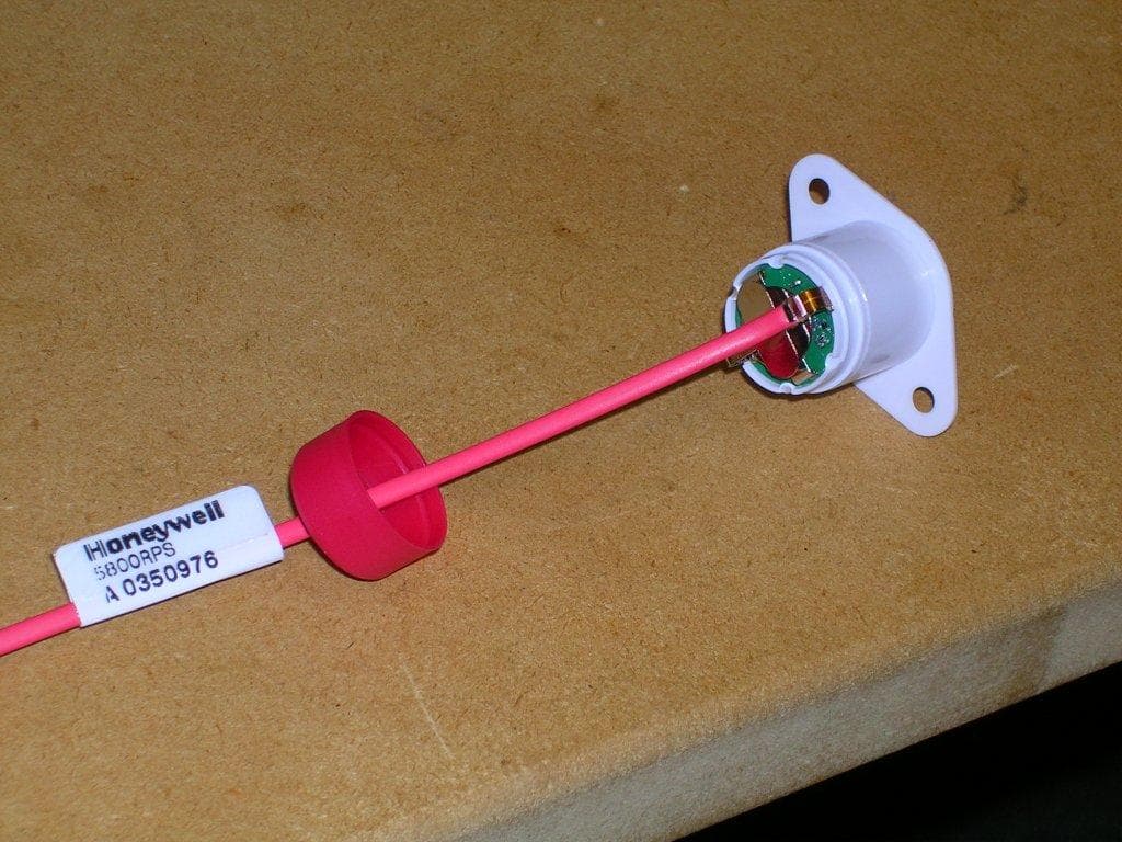
Click to zoom
Application Details
- Equipment Class
- DSC - Part 15 Security/Remote Control Transmitter
- Date of Grant
- Feb 05, 2012
- Application Purpose
- Original Equipment
- Date of Application
- Feb 05, 2012
- Equipment Note
- SECURITY DEVICE/ALARM SYSTEM RECESSED TRANSMITTER
- Frequency Range
- 344.94000000 - 344.94000000
- Company
- Ion Digital LLP
- Country
- United States
Documents & Files
Document Text
Text extracted from the exhibit documents filed with the FCC. Open a document above to read the original.
Users Manual
1 2 3 5800MICRA RecessedTransmitter Insertthe5800MICRA'santennaintothe extrusionhollowthenpressthetransmitter bodyintotheopening. Undernocircumstancesshouldtheouterwallofthewindow framebepenetratedbytheForstnerbit. Adrillstopcanbeusedtoensuretheouterwallofthewindow frameisnotdamaged. Figure1. Measure&Drill Usinga3/4"ForstnerDrillBit, drillintothevinylewindow mainframe. WARNING: undernocircumstances shouldtheouterwallofthewindow framebepenetratedbytheForstnerbit. Sidemount transmitter onVinyl Sliders outer wall of Antenna window frame inner wall of window frame 3/4" Forstner drill bit Measure3"downfromtheinsidetopcornerofthe mainframeandmarkthecenterpointfortheholethe 5800MICRAtransmitterwillbeinsertedinto. Placeacorrespondingmarkalsoonthesashwherethe magnetwillbeplaced. Sillmounttransmitter onHungWindows Horizontal Sliding Sash Vertical Sliding Sash 0.5" < extrusion hollow > 11/32" core depth PlaceandSet NOTE:Itisessentialtothesystemsoperationthat thepositioningofthe5800MICRAtransmitterpointin thesamedirectionasitscorrespondingmagnet. Removeadhesivebackingandplaceon desiredlocation. GENERALINFORMATION TheHoneywell5800MICRAwirelessrecessedtransmitterisareedswitch magneticcontacttransmitterthatallowsthetransmittertobeconcealed fromviewwheninstalledinawindow.Itisintendedforuseonlywithalarm systemsthatsupportHoneywell5800seriesdevices.Thetransmitteris poweredbyalong-lifelithiumbatterythatiseasilyreplaceablewhenalow batteryisindicatedbythecontrolpanel. ProgrammingtheSerialNumber Each5800MICRAhasitsownuniqueserialnumberpermanentlyassigned duringmanufacturing. Thecontrolpanelisusedto"enroll"thetransmitter'sIDduringinstallationof thealarmsystem.Thezonesinputtypeshouldbeas"RF"(i.e.SupervisedRF) Type. Refertothecontrolpanel'sinstallationinstructionsforfurtherdetails. PRELIMINARYCONSIDERATIONS Readallofthisandthenextsectionbeforeinstallingtheunit. 1.Selectalocationforthetransmitterontheframeofthewindow. Donotuseonmetalframedoorsorwindows. 5800MICRATRANSMITTER The5800MICRAtransmitterwillrequirea3/4"diameterhole(using a3/4"Forstnerbit)drilledintotheedgeofthewindowframenomore than11/32"deep. BEFOREDRlLLlNGANYHOLES,SEEITEM2BELOWANDMOUNTlNG SECTIONONPAGE2. FORVINYLSLIDINGWINDOWSthepreferreddirectionofmountingisvertical. FORHUNGWINDOWSthe5800MICRAmustbemountedhorizontallyinthe windowsillwiththeaccompanyingmagnetmountedonthelowerwindowsash. (seeStep1-Measure&DrillinFigure1) 2.Beforedrillinganyholes,tapethetransmitterandmagnetintheir approximatelocations(withbatteryinstalledandunittogetheras describedunderBATTERYINSTALLATION/REPLACEMENT;seepageback) a n dconductGo/NoGotests(seecontrol'sinstructions)toverify adequatesignalstrength.Reorientorrelocatethetransmitterifnecessary. Makesurethatnomorethana1/2"gapwillbepresentbetweenthefaces ofthetransmitterandmagnetcaseswhentheyareinstalledandset.Alsomake surethegraphiconthetransmitterandmagnetisperpendiculartothelength ofthemagnetperStep3. Wheninstalled,analarmsignalmustbeobtainedbeforeaclearspaceof2" isreachedasthewindowisopened. InstallationInstructions SurfaceMounted MagnetPlacement SurfaceMount Magnet 5800MICRA TRANSMITTER
Cover Letter(s)
January 24, 2012 Federal Communications Commission Authorization and Evaluation Division Confidentiality Request FCC ID: QN35800XT Pursuant to Sections 0.457 and 0.459 of the Commissions Rules, the Applicant hereby requests confidential treatment of information accompanying this Application as outlined below: Schematics Block Diagram & Operation Descriptions Bill of Materials The above materials contain trade secrets and proprietary information not customarily released to the public. The public disclosure of these matters might be harmful to the Applicant, and provide unjustified benefits to it’s competitors. Sincerely, Dean Schebel Director - Engineering I O N D I G I T A L L L P I O N D I G I T A L L L P • P O B O X 3 9 6 9 • B L A I N E W A , U S A 9 8 2 3 1 P H O N E : 1 - 8 0 0 - 4 0 7 - 4 3 8 9 • F A X : 1 - 8 0 0 - 4 0 7 - 4 4 6 5
Test Report
ION DIGITAL LLP 5800 MICRA Duty Cycle Correction factor On a change of state, 6 identical packets are transmitted at random intervals. The time interval between each packet is no less than 100mS and averages 125 mS. Each packet is 64 bits (16 bits preamble, 48 bit data) transmitted as PWM-ASK modulation. Bits are Phase Encoded (Manchester) at baseband, so the duty cycle is exactly 50%. Each bit cell interval is 0.27mS, so the total on time per packet is: On Time = 64 bits * 0.5 on/bit * 0.27mSec = 8.64 mSec Thus, for every 100 ms, we are transmitting for 8.64 ms of that time period. Therefore our duty cycle correction factor (in the worst case 100mSec period) is: DUTY CYCLE CORRECTION FACTOR (dB) = 20*Log(0.0864) = -21.3 dB Transmission Time Duration from Trigger Point to End of Transmission The processor samples the reed switch approximately once per second. After detecting a change of state, it constructs the packet (1mS), then enables the VCO on the transmitter to power up (10mS), but does not transmit during that time. Then 4 packets (29 mS each) are sent, with a random timeout between them (100mS – 800mS). Therefore the total duration time from when the device is triggered, to when transmission is completed and turned off (worst case) is 3.527 seconds. 0.000s Trigger Point 2.000s Microprocessor sample time (on close of reed switch worst case) 0.002s Microprocessor setup time for packet construction and transmitter warmup (worst case) 0.645s Sextet Packet Transmission (1 st group of 6 packets) 1.305s worst case delay between sextet#1 and sextet #2 0.770s Sextet Packet Transmission (2 nd group of 6 packets) 4.722s Total worst case duration from when device is triggered to transmission completed/off. Timing plots are given below. Figure 1 Transmitted (1 st Sextet) Data Packets, 100ms/div Figure 2 Transmitted Data Packet, 2.0 ms/div Figure 3 Transmitted Data Packet, 0.5 ms/div
Test Report
EMC Directive Compliance Test Report Rev. 1.3 ION Digital LLP: 5800 MICRA/RPS Report Number: PR11-049 Page 1 of 17 ION Digital LLP 5800 MICRA/RPS EMC DIRECTIVE COMPLIANCE TEST REPORT per FCC CFR47 Part 15 Subpart B 15.231 & IC RSS-GEN Issue 3 IC RSS-210 Issue 8 Annex 1 FCC ID: QN3 5800XT IC Certification Number: 4488A-5800XT Revision 1.3 Jan 26 th , 2012 Jan. 26 h , 2012 Protocol Data Systems Inc, EMC Lab, Abbotsford BC, Canada. SCC ISO/17025 (CAN-P-4E) Accredited Laboratory No. 612 FCC O.A.T.S. Registration Number 627740 Industry Canada O.A.T.S. Registration Number IC3384A-1 This report is for the exclusive use of Protocol Data Systems Customer and is provided pursuant to the agreement between Protocol and its Customer. Protocol's responsibility and liability are limited to the terms and conditions of the agreement. Protocol assumes no liability to any party, other than to the Customer in accordance with the agreement, for any loss, expense or damage occasioned by the use of this report. Only the Customer is authorized to copy or distribute this report and then only in its entirety. Any use of the Protocol Data Systems name for the sale or advertisement of the tested material, product or service must first be approved in writing by Protocol Data Systems. The observations and test results in this report are relevant only to the sample/s tested. EMC Directive Compliance Test Report Rev. 1.3 ION Digital LLP: 5800 MICRA/RPS Report Number: PR11-049 Page 2 of 17 Index Section I: Report of Measurement Testing Information ............................................. 3 Section II: Report of Measurement Test Procedures .................................................. 9 Section III: Report of Measurement to Radiated Emissions ...................................... 10 Section IV: 20dB Bandwidth Testing .......................................................................... 12 Appendix A: Fundamental, Harmonics and Spurious Emissions Data and Plots ......... 14 EMC Directive Compliance Test Report Rev. 1.3 ION Digital LLP: 5800 MICRA/RPS Report Number: PR11-049 Page 3 of 17 Section I: Report of Measurement Testing Information General Information Applicant Company Name ION Digital LLP Address Unit 2109, 1225 Kingsway Ave Port Coquitlam,BC V3C 1S2 Phone: 800-407-4389 Fax 800-407-4465 Contact Person: Dean Schebel Email: [email protected] Product Name Intrusion Detector Sensor – Plunger Plastic with Wire Antenna FCC ID# QN3 5800XT IC Certification Number 4488A-5800XT Applicable Standards FCC CFR Title 47 Part 15 Subpart B 15.231, ANSI C63.4:2003; IC RSS-GEN Issue 3 and IC RSS-210 Issue 8 Annex 1 Test Results PASS Related Report/s Approval ION Digital RN 03330, PR11-032, PR11-040 Statement of Compliance This equipment has been tested in accordance with the standards indentified in the referenced test report. To the best of our knowledge and belief, these tests were performed using the measurement procedures described in this report and demonstrate that the equipment complies with the appropriate standards. – Signature on Front Cover Page. Equipment Under Test Specification Manufacturer ION Digital LLP Product Description Intrusion Detector Sensor – Plunger Plastic with wire Antenna FCC ID# QN3 5800XT IC Certification Number 4488A-5800XT Model Number 5800MICRA (UNIT #3) & 5800RPS (UNIT #1) Description Intrusion Detector Recesses Transmitter Operating Frequency 344.94 MHz Emission Designator Modulation Type Amplitude Shift Keyed – On/Off Keyed: ASK-OOK Bit Rate 3.7 kbit/s Rated Transmit Power 2 dBm EUT Power Source 3 V DC Coin Cell Battery Test Item EMC Test Unit Type of Equipment Fixed Wire Antenna Antenna Connector Permanently Attached Test Voltage 3 V DC Coin Cell Battery Test Environment Test Facility Protocol Data Systems Inc. 4741 Olund Rd. Abbotsford, BC V4X 1V6 Office Phone: 604-504-0091 Cell Phone: 604-761-0106 Fax: 604-554-0091 Email: [email protected] Website: www.protocol-emc.com Test Facility ID’s SCC ISO/17025 (CAN-P-4E) Accredited Laboratory No. 612 FCC O.A.T.S. Registration Number 627740 Industry Canada O.A.T.S. Registration Number IC3384A Date Tested December 6 th & 7 th , 2011 Tested By Simon Howkins EMC Directive Compliance Test Report Rev. 1.3 ION Digital LLP: 5800 MICRA/RPS Report Number: PR11-049 Page 4 of 17 Test Setup Test Supporting Equipment None Required Test Conditions December 6 th , 2011: 4°C, 75% R.H. December 7 th , 2011: 5°C, 83% R.H. January 26 th , 2012: 5°C, 75% R.H. Test Exercise e.g. software description, test signal, etc. The EUT was set for continuous transmit mode of operation. It only has 1 frequency. The options were for a CW and modulated frequency. All test were conducted with the transmitter`s modulation on. Deviation from Standard/s No deviation from standards. Modification to the EUT No modifications were made. Test Equipment List Manufacturer Model Equipment Description Serial No. Next Cal HP 85650A Quasi-Peak Adapter 2811A01080 12/8/2012 HP 85662A Spectrum Analyzer Display 2152A03569 11/8/2012 HP 8566B Spectrum Analyzer RF Section 2241A02102 11/8/2012 HP 85685A RF-Preselector 3107A01222 11/8/2012 EMCO 6502 Active Loop Antenna 0.15-30MHz 9002-2489 15/10/2012 EMCO 3146 Ant. Log Periodic 200-1000MHz 9611-4699 8/8/2012 EMCO 3110B Ant. Biconical 30-200MHz 9401-1850 8/8/2012 EMCO 3115 Horn Antenna 1-18GHz 9403-4251 20/8/2012 HP 362 Controller 6452A40248 N/A OPERATIONAL DESCRIPTION Rhientech Custom Antenna Mast N/A N/A Protocol EMC Custom Turntable N/A N/A Measurement Uncertainty Parameter Uncertainty Radio Frequency ±1 x 10⁻⁵ MHz Radiated Emissions ±3 dB Temperature ±1°C Humidity ±5 % DC and low frequency voltages ±3 % EMC Directive Compliance Test Report Rev. 1.3 ION Digital LLP: 5800 MICRA/RPS Report Number: PR11-049 Page 5 of 17 Section II: Report of Measurement Test Procedures Radiated Interference: The measurement was made per ANSI C63.4-2003 using an Agilent model 8566B spectrum analyzer, a model 85685A Preselector, a model 85650A qua…
Text truncated - open the document above for the full version.
Test Setup Photos
RADIATED EMISSIONS TEST SETUP PICTURES: ION DIGITAL 5800 MICRA RPS.
Contact Information
Applicant
Dean Schebel(RF Design Engineer)
Test Firm
Protocol Data Systems Inc.Robert Stirling
[email protected]6042181762
Technical Specifications
| # | Rule Parts | Frequency Range | Power Output |
|---|---|---|---|
| 1 | 15.231 | 344.94 MHz - 344.94 MHz | - |
Other Applications from Ion Digital LLP
QN35800M
Oct 05, 2004SECURITY WIRELESS WINDOW SENSOR
Equipment Class
DSC - Part 15 Security/Remote Control Transmitter
QN3WD01
Nov 04, 2002Security/Remote Control Transmitter
Equipment Class
DSC - Part 15 Security/Remote Control Transmitter
QN3FP01
Nov 04, 2002Security/Remote Control Transmitter
Equipment Class
DSC - Part 15 Security/Remote Control Transmitter