QN8MC200MCardiac Monitoring System
Seers Technology Co., Ltd.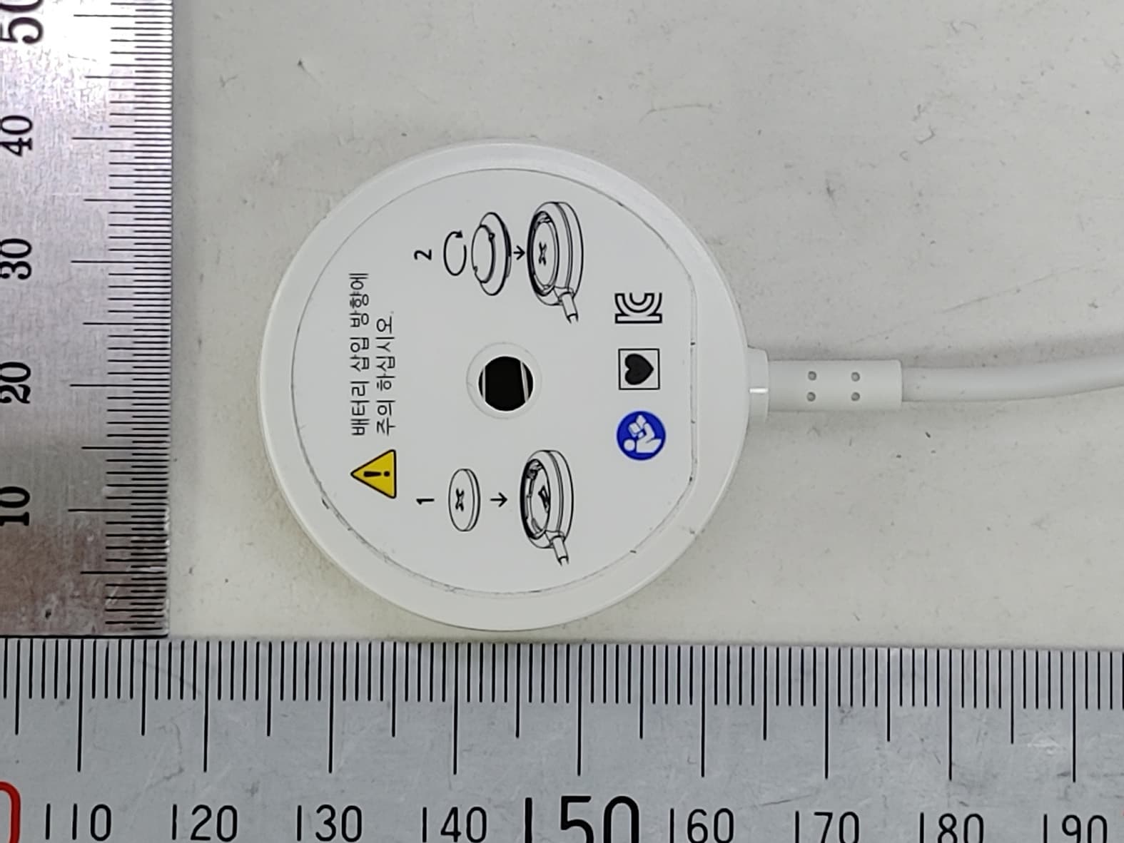
Click to zoom
Application Details
- Equipment Class
- DTS - Digital Transmission System
- Date of Grant
- Apr 21, 2021
- Application Purpose
- Original Equipment
- Date of Application
- Apr 19, 2021
- Equipment Note
- Cardiac Monitoring System
- Frequency Range
- 2402.00000000 - 2480.00000000
- Company
- Seers Technology Co., Ltd.
- Country
- South Korea
Documents & Files
Document Text
Text extracted from the exhibit documents filed with the FCC. Open a document above to read the original.
Users Manual
Doc. No. : ST-UM-MC200Ms-HA[E] Vev. No. : 1.0v Issued date : 2020.01.25 User Manual Holter Monitor Model name : mobiCARE-MC200M mobiCARE-MC200ML mobiCARE-MC200M7 mobiCARE-MC200ML7 2 Table of Contents 1. PRODUCT INTRODUCTION ...................................................................................... 3 2. MEDICAL SAFETY .......................................................................................................... 8 3. COMPONENTS AND INSTALLATION ..................................................................13 4. HOW TO USE MOBICARE-MC200M SERIES ...................................................17 5. LABELS AND PACKAGING .......................................................................................31 6. EXPECTED SERVICE LIFE TIME AND WARRANTY .........................................35 7. MANUFACTURE INFORMATION ...........................................................................36 8. DECLARATION OF CONFORMITY ........................................................................37 3 1. Product Introduction 1.1. Intend of Use - mobiCARE-MC200M/mobiCARE-MC200ML/ mobiCARE-MC200M7/ mobiCARE-MC200ML7 (hereinafter “mobiCARE-MC200M series”) is a light-weight electrocardiogram (ECG) and heart rate (HR) monitoring device with accompanying software. The mobiCARE-MC200M series operates wirelessly, and due to compact size is unobtrusive during daily activity. The mobiCARE-MC200M series continuously measures ECG and HR signals and measures the change in impedance for respiration rate and electrode status. And also, if necessary, measures the change in movement of the person with the product attached using the IMU sensor, and then stores measured data on the memory. Simultaneously, mobiCARE-MC200M series streams digitized signals to a mobile gateway device equipped with the mobiCARE Cardo Hospital App /mobiCARE Cardio Diary App. At the end of ECG recording, they upload measured data to a secure cloud portal via PC uploader program. After data upload takes place, physicians can access and review their patients’ ECG data remotely via the mobiCARE Cardio Web. The difference between four models is length of the 'Connect Cable' and size of the 'Coin Battery'. The length and size of the mobiCARE- MC200M is 180mm & CR2450R, mobiCARE-MC200ML is 250mm & CR2450R, mobiCARE-MC200M7 is 180mm & CR2477, mobiCARE- MC200ML7 is 250mm, CR2477, Others are both same. Model name Cable length Battery size mobiCARE-MC200M 180mm CR2450R mobiCARE-MC200ML 250mm CR2450R mobiCARE-MC200M7 180mm CR2477 mobiCARE-MC200ML7 250mm CR2477 [Model difference] The mobiCARE-MC200M series is intended to be used with direction from trained medical professionals in accordance with the user manual. - Product name : Cardiac Monitoring System - Model name : mobiCARE-MC200M / mobiCARE-MC200ML / 4 mobiCARE-MC200M7 / mobiCARE-MC200ML7 - Manufacturer : Seers Technology Co., Ltd. 1.2. Intended purpose of the device Intended Use The mobiCARE-MC200M series is a Heart/Cardiovascular Disease Monitoring system for measuring and analyzing patient electrocardiogram (ECG) waveforms and heart rate (HR). The product consists of bio-signal sensing device, mobile application and web portal of electrocardiogram analysis for physician. Indication for use Arrhythmia 1.3. Marks and Symbols Label Symbol Description 1 The serial number that identifies the object. 2 Date of manufacture 3 Manufacturer 4 Caution / Warning 5 Instruction for User Manual 6 Type of applied part 7 Prescription only 8 WEEE Mark 5 9 Keep Dry 10 Temperature limit 11 Humidity limitation 12 Authorized European Representative address 13 The CE symbol indicates that this product complies with the European Directive for Medical Devices 93/42/EEC as amended by 2007/47/EC as a class IIa device. 14 Non-ionizing radiation 15 MR unsafe 1.4. Intended Patient population 1) Age : ALL 2) Weight : ALL 3) Health : (1) Do not use Patients with artificial cardiac pacemaker, cardioverter defibrillator, or other implantable electric devices. (2) Do not use for pregnant women or breast-feeding mothers (3) To be used at physician discretion on patients if patient presents current sign or medical history of skin cancer, rash, skin disorder, keloid, and/or any injury. 4) Nationality : Not limited 5) Patient state : Not limited 1.5. Intended part of the body or type of tissue applied to or interacted with 1) Intended part of the body : Near Heart on the BODY 2) Type of tissue : Skin 6 1.6. Intended user profile 1) Education - Minimum : (1) Main unit / Application : Patient with at least 10 years education can use the product alone, and patient without at least 10 years education (ex, child, etc.) or patient who need help (ex, senior) can use it under the care of their parents or guardian (2) Web software : Those who have a professional license - Maximum : No maximum 2) Knowledge - Minimum : It is necessary to understand the numerical values and the overall description in Korean or English manual for ECG main unit and Mobile App. Medical knowledge for Web software to analysis - Maximum : No maximum 3) Language understanding - Be able to understand the numerical values and general technical information presented in the user manual written in Korean or English 4) Experience - No special experience needed and no maximum for ECG main unit and Mobile App. - Experience need to analyze the cardiac monitoring 5) Permissible impairment - Mild reading vision impairment or vision corrected to log MAR 0.2(6/10 or 20/32) - Impaired by 40% resulting in 60% of normal hearing at 50Hz to 2kHz 6) Others (1) At least the electrocardiogram graph must be confirmed (2) At least you need to install the app on your phone and use the installed app 7 (3) At a minimum, the viewer program must be installed on the computer and the installed program must be available. 1.7. Use environment 1) Environment - General : Home, Hospital environment, Indoor, Outdoor - Physical (1) Temperature : 5 ~ 40°C (2) Relative…
Text truncated - open the document above for the full version.
Cover Letter(s)
Seers Technology Co., Ltd. (Sangdaewon-dong, techcenter 1314) 124, Sagimakgol-ro, Jungwon-gu, Sungnam-si, Gyeonggi-do, South Korea Date: 04/20/2021 Timco Engineering, Inc. 849 N.W. State Road 45 P.O. Box 370 Newberry, Florida 32669 USA Letter of Authorization We, the undersigned, hereby authorize Geunki Son of DT&C Co., Ltd. to act on our behalf in all manners relating to application for equipment authorization for FCC ID: QN8MC200M including signing of all documents relating to these matters. Any and all acts carried out by Geunki Son of DT&C Co., Ltd. on our behalf shall have the same affect as acts of our own. This authorization is valid until further written notice from Seers Technology Co., Ltd. “I, the undersigned, hereby certify that we are not subject to a denial of federal benefits, that includes FCC benefits, pursuant to Section 5301 of the Anti-Drug Abuse Act of 1988, 21 U.S.C. 853(a).” Sincerely, Name: Dae Yeop, Kang Position: president
Cover Letter(s)
Seers Technology Co., Ltd. (Sangdaewon-dong, techcenter 1314) 124, Sagimakgol-ro, Jungwon-gu, Sungnam-si, Gyeonggi-do, South Korea Date: 04/20/2021 Timco Engineering, Inc. 849 N.W. State Road 45 P.O. Box 370 Newberry, Florida 32669 USA RE: Request of Confidentiality for FCC ID: QN8MC200M To Whom It may Concern: Pursuant to Sections 0.457 and 0.459 of the Commission`s Rules(CFR 47), and Section 552 (b) (4) of the Freedom of Information Act, Seers Technology Co., Ltd. hereby requests confidentiality and treatment of certain information accompanying this application. The materials contain trade secrets and proprietary information not customarily released to the public. The public disclosure of these matters might be harmful to the Applicant and provide unjustified benefits to its competitors. We are also hereby request Short-Term Confidentiality for 180 days after the grant as outlined in Public Notice DA 04-1705. This provision will give Seers Technology Co., Ltd. temporary confidentiality of commercially sensitive information prior to product release. The requested permanent and Short-Term Confidential exhibits are listed as follows: PERMANENT & SHORT-TERM CONFIDENTIAL LIST Exhibit Description PERMANENT 1 Block Diagram 2 Schematics 3 Part Lists 4 Operation Description 5 NA SHORT-TERM 6 Internal Photos 7 External Photos 8 Test-Setup Photos 9 User Manual The Applicant understands that pursuant to Rule 0.457, disclosure of this application and all accompanying documentations, where applicable, will not be public before the date of the Grant for this application. Sincerely, Name: Dae Yeop, Kang Position: president
External Photos
FCC ID: QN8MC200M Copyright Ⓒ 2021, DT&C Co., Ltd. View 1 FCC ID: QN8MC200M Copyright Ⓒ 2021, DT&C Co., Ltd. View 2 FCC ID: QN8MC200M Copyright Ⓒ 2021, DT&C Co., Ltd. View 3 FCC ID: QN8MC200M Copyright Ⓒ 2021, DT&C Co., Ltd. View 4 FCC ID: QN8MC200M Copyright Ⓒ 2021, DT&C Co., Ltd. View 5 FCC ID: QN8MC200M Copyright Ⓒ 2021, DT&C Co., Ltd. View 6 FCC ID: QN8MC200M Copyright Ⓒ 2021, DT&C Co., Ltd. View 7 FCC ID: QN8MC200M Copyright Ⓒ 2021, DT&C Co., Ltd. View 8 FCC ID: QN8MC200M Copyright Ⓒ 2021, DT&C Co., Ltd. View 9
ID Label/Location Info
FCC ID : QN8MC200M Copyright Ⓒ 2021, DT&C Co., Ltd. SAMPLE LABEL & LOCATION LABELLING REQUIREMENTS The Label shown shall be permanently affixed at a conspicuous location on the device and be readily visible to the user at the time of purchase. Sample label Location - The FCC label shown is representative of the label that will appear on the radio when in production. Other information may also be included on this label.
Internal Photos
FCC ID: QN8MC200M Copyright Ⓒ 2021, DT&C Co., Ltd. View 1 <Antenna> FCC ID: QN8MC200M Copyright Ⓒ 2021, DT&C Co., Ltd. View 2 FCC ID: QN8MC200M Copyright Ⓒ 2021, DT&C Co., Ltd. View 3 <Antenna> FCC ID: QN8MC200M Copyright Ⓒ 2021, DT&C Co., Ltd. View 4 FCC ID: QN8MC200M Copyright Ⓒ 2021, DT&C Co., Ltd. View 5 FCC ID: QN8MC200M Copyright Ⓒ 2021, DT&C Co., Ltd. View 6
RF Exposure Info
FCC ID: RF feauture Mode Transmitting Frequency(MHz) Test separation distance (mm) ANT Gain (dBi) Max. power with tune-up tolerance (dBm) Note1 Max. power with tune-up tolerance (mW) Power thresholds SAR test exclusion thresholds BLE 1 Mbps 2 480.00 5.0 4.53 0.00 1.000 0.31 3.00 BLE 2 Mbps 2 480.00 5.0 4.53 0.00 1.000 0.31 3.00 Note1. Conclusion : Note. The calculation result was rounded to two decimal place f or comparison. QN8MC200M Please refer to the operation description for Max tune-up. Standalone SAR test exclusion considerations SAR evaluation for general popul ation exposure conditions by me asurement or numerical simulation is not required KDB 447498 D01 clasue 4.3.1 Step 1) SAR test exclusion thresho lds for 100MHz to 6GHz at test separationn distances ≤ 50 mm [ ( max. power of channel, inclu ding tune-up tolerance, mW ) / ( min. test separation distance, mm ) ] · [ √f(GHz) ] ≤ 3.0 for 1g SAR and ≤ 7.5 for 10g extremity SAR Sample Calculation = [ ( 1mW / 5mm ) ] X [ √2.48GHz ] = 0.31
Test Report
Report No.: DRTFCC2104-0033 FCC ID: QN8MC200M This test report is prohibited to copy or reissue in whole or in part without the approval of DT&C Co., Ltd. TRF-RF-238(06)210316 Pages: 2 / 56 Test Report Version Test Report No. Date Description Revised by Reviewed by DRTFCC2104-0033 Apr. 20, 2021 Initial issue JaeHyeok Bang JaeJin Lee Report No.: DRTFCC2104-0033 FCC ID: QN8MC200M This test report is prohibited to copy or reissue in whole or in part without the approval of DT&C Co., Ltd. TRF-RF-238(06)210316 Pages: 3 / 56 Table of Contents 1. General Information .................................................................................... 4 1.1 Testing Laboratory ........................................................................................................... 4 1.2 Test Environment ............................................................................................................. 4 1.3 Measurement Uncertainty ................................................................................................ 4 1.4 Details of Applicant .......................................................................................................... 5 1.5 Description of EUT ........................................................................................................... 5 1.6 Declaration by the applicant / manufacturer ................................................................. 5 1.7 Test Equipment List ......................................................................................................... 6 1.8 Summary of Test Results ................................................................................................ 7 2. Test Methodology ........................................................................................ 8 2.1 EUT Configuration ............................................................................................................ 8 2.2 EUT Exercise ..................................................................................................................... 8 2.3 General Test Procedures ................................................................................................. 8 2.4 Description of Test Modes ............................................................................................... 8 2.5 Instrument Calibration ..................................................................................................... 8 3. Test Result ................................................................................................... 9 3.1 Maximum Peak Conducted Output Power ..................................................................... 9 3.1.1 Test Setup ..................................................................................................................... 9 3.1.2 Test Procedures ........................................................................................................... 9 3.1.3 Test Results .................................................................................................................. 9 3.2 6 dB Bandwidth Measurement ...................................................................................... 14 3.2.1 Test Setup ................................................................................................................... 14 3.2.2 Test Procedures ......................................................................................................... 14 3.2.3 Test Results ................................................................................................................ 14 3.3 Maximum Power Spectral Density. ............................................................................... 19 3.3.1 Test Setup ................................................................................................................... 19 3.3.2 Test Procedures ......................................................................................................... 19 3.3.3 Test Results ................................................................................................................ 19 3.4 Unwanted Emissions (Conducted) ............................................................................... 24 3.4.1 Test Setup ................................................................................................................... 24 3.4.2 Test Procedures ......................................................................................................... 24 3.4.3 Test Results ................................................................................................................ 25 3.5 Unwanted Emissions (Radiated) ................................................................................... 41 3.5.1 Test Setup ................................................................................................................... 42 3.5.2 Test Procedures ......................................................................................................... 42 3.5.3 Test Results ................................................................................................................ 43 3.6 Power line Conducted Emissions ................................................................................. 45 3.6.1 Test Setup ................................................................................................................... 45 3.6.2 Test Procedures ......................................................................................................... 45 3.6.3 Test Results ................................................................................................................ 45 4. ANTENNA REQUIREMENTS ..................................................................... 48 APPENDIX I .................................................................................................... 49 APPENDIX II .............................................................................…
Text truncated - open the document above for the full version.
Test Setup Photos
FCC ID: QN8MC200M Copyright Ⓒ 2021, DT&C Co., Ltd. Test Setup photographs EUT Position: X-axis EUT Position: Y-axis EUT Position: Z-axis FCC ID: QN8MC200M Copyright Ⓒ 2021, DT&C Co., Ltd. Test Setup Photo of Radiated Measurement (0.009 ~ 30MHz) FCC ID: QN8MC200M Copyright Ⓒ 2021, DT&C Co., Ltd. Test Setup Photo of Radiated Measurement (Below 1GHz) FCC ID: QN8MC200M Copyright Ⓒ 2021, DT&C Co., Ltd. Test Setup Photo of Radiated Measurement (Above 1GHz) FCC ID: QN8MC200M Copyright Ⓒ 2021, DT&C Co., Ltd. Test Setup Photo of AC Line Conducted Measurement
Contact Information
Applicant
Dae Yeop Kang
Test Firm
Dt&C Co., Ltd.Lee Sang-Wook
Technical Specifications
| # | Rule Parts | Frequency Range | Power Output |
|---|---|---|---|
| 1 | 15C | 2.40 GHz - 2.48 GHz | 1.00 mW |
Other Applications from Seers Technology Co., Ltd.

QN8MT110H
Oct 30, 2023Temperature monitoring system
Equipment Class
DTS - Digital Transmission System
QN8MP100W
Nov 10, 2022mobiCARE+ Pulse
Equipment Class
DTS - Digital Transmission System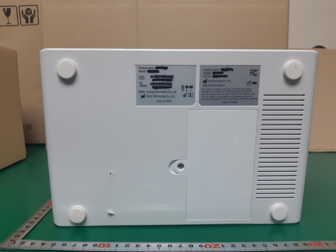
QN8-MH100
Mar 22, 2021Telehealth Gateway
Equipment Class
DTS - Digital Transmission System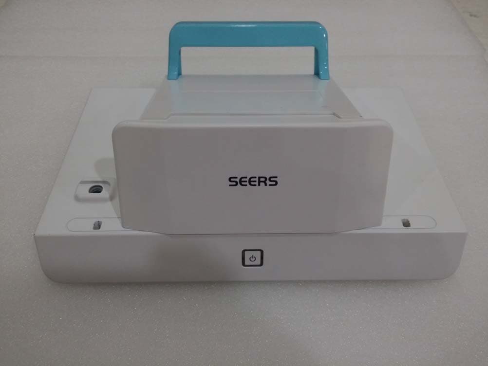
QN8HH-800
Mar 16, 2015HICARE HUB
Equipment Class
DTS - Digital Transmission System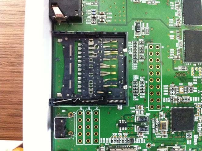
QN8HX-461
Nov 28, 2012AUTO BLOOD PRESSURE METER
Equipment Class
DTS - Digital Transmission System