QO7AIS3410Maritime AIS Transponder
SAM Electronics GmbH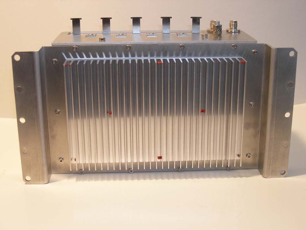
Click to zoom
Application Details
- Equipment Class
- AIS - Automatic Identification Systems
- Date of Grant
- Jul 04, 2010
- Application Purpose
- Original Equipment
- Date of Application
- Jul 04, 2010
- Equipment Note
- Maritime AIS Transponder
- Frequency Range
- 156.02500000 - 162.02500000
- Company
- SAM Electronics GmbH
- Country
- Germany
Documents & Files
Document Text
Text extracted from the exhibit documents filed with the FCC. Open a document above to read the original.
Users Manual
Technical Manual Automatic Identification System AIS 3410 Electronics Unit Item No.: ED3047G842Revision: 01 (2009-08)Order No.: 390007907 t_ue_eti.fm / 27.08.09 © SAM Electronics GmbH 2009 This document is our property for which we reserve all rights, including those relating to patents or registered designs. It must not be reproduced or used otherwise or made available to any third party without our prior permission in writing. Alterations due to technical progress are reserved. SAM Electronics GmbH D - 22763 Hamburg Service Customer Support Center Phone:+ 49 (0) 18 03 00 85 53 Fax:+ 49 (0) 18 03 00 85 54 E-mail: [email protected] AIS 3410, Electronics Unit ED3047G842 / 01 (2009-08) Technical Manual List of Contents t_ue_eIV.fm / 27.08.09 3 List of Contents List of Contents 3 List of Figures 5 List of Abbreviations 7 1General 9 1.1Software Releases 9 1.2General Recommendations for Installation, Maintenance and Repair Work 9 1.3Safety Warnings 9 2Overview 11 2.1Compatibility with Other Systems 11 2.2AIS 3410 in RADARPILOT 1000/1100 Systems 12 2.3AIS 3410 in 1000/1100 Series Systems (NACOS xx-4 and xx-5) 13 2.4AIS 3410 in CHARTPILOT Stand-alone Systems 14 2.5AIS 3410 in NACOS xx-3 Systems (Radar 9xxx and CHARTPILOT) 15 2.6AIS 3410 in Radar 9xxx Systems with RADARPILOT 1000/1100 16 2.7AIS 3410 in Radar 9xxx Systems 17 2.8Housing of the 3410 Electronics Unit 18 2.9Replacement of AIS Electronics Unit 19 2.9.1Open the Housing of AIS 3410 19 2.9.2Open the Housing of UAIS DEBEG 3400 19 2.9.3Merge the AIS 3410 Electronics Unit into the UAIS DEBEG 3400 Housing 20 2.10Media Converter Installation (necessary for ships with BNC LAN networks) 20 3Installation Recommendations 21 3.1General Recommendations 21 3.1.1Cables 21 3.1.1.1Maximum Cable Length 22 3.1.1.2Cable Sets 23 3.1.2Electronics Units 23 3.2Specific Recommendations 24 3.2.1Recommendations Concerning AIS Systems 24 3.2.2Recommendations Concerning the Installation of the Electronics Unit 25 3.2.3Recommendations Concerning the Installation of the Antennas 25 3.2.3.1Recommendations Concerning the Installation of the VHF Antenna 26 3.2.3.2Recommendations Concerning the Installation of the GPS Antenna 27 3.2.4Recommendations Concerning Redundancy 28 3.2.5Recommendations Concerning the Connection of a (D)GPS to AIS 3410 28 3.2.6Emergency Power Source 28 3.2.7Pilot Port, Connector/Cable Kits 28 3.2.8Recommendations Concerning AIS Stand-alone with Radar 9xxx / NACOS xx-2/-3 29 3.2.9Recommendations Concerning the Connection to a Radar 1000/1100 Series System 29 3.2.10Recommendations Concerning the Connection to a Radar 1100 Series System 29 4Functional Description 31 4.1Block Diagram 31 4.2Termination 32 4.3Description of the Components 33 4.3.1AIS 3410 Electronics Unit 33 4.3.1.1Interfaces 34 4.3.1.2Internal Connectors 35 4.3.1.3Supported Sensor Input Sentences 35 4.3.1.4Supported Sentences for the AIS Primary Display Port and the Pilot Port 37 4.3.1.5Supported Sentences for the Long Range Port 38 4.3.1.6Supported Sentences for the Internal Position Sensor 40 4.3.1.7IEC 61162 -1/-2 Interfaces, Electrical Characteristics 41 4.3.1.8Example for the Interconnection 42 4.3.2VHF Antenna 42 AIS 3410, Electronics Unit ED3047G842 / 01 (2009-08) Technical Manual List of Contents t_ue_eIV.fm / 27.08.09 4 4.3.3GPS Antenna 43 4.3.4Pilot Port 43 5Setting-to-Work/Configuration 45 5.1Setting-to-Work 45 5.2Software Versions 45 5.3Configuration 45 5.3.1Configuration with RADARPILOT/CHARTRADAR/MULTIPILOT 1000/1100 - NACOS xx-4/5 Systems 45 5.3.2Configuration with CHARTPILOT 93xx in NACOS xx-3 Systems 46 5.3.3Configuration with Radar 9xxx 46 5.4Testing 46 5.5LEDs for Ethernet LAN, Alarm, GPS and Telegram 46 6Repair/Maintenance 47 6.1Trouble Shooting 47 6.1.1Hints 47 6.1.2Fault Tree 48 6.1.3Trouble Shooting for AIS 3410 connected to a RADARPILOT 1000/1100 49 6.1.3.1Indication: System Fault Message 3617 Displayed on Indicator 49 6.1.3.2Indication: System Fault Message 3616 Displayed on Indicator 54 6.2Test of the Antenna Performance 54 6.3Software Update 54 6.3.1Software download from SAM-CMIS 54 6.3.2Determination of the Current Software Versions 55 6.3.3Serial Cable Connection 55 6.3.4Software Update by means of a Laptop 56 6.3.5Software Update by means of a CHARTPILOT or MULTIPILOT 91x0 57 6.4Opening the Housing 58 6.4.1Fuses 58 6.4.2Antennas 58 6.5Spare Parts 58 7Technical Data 59 7.1Conformity to Standards, Environmental Conditions 59 7.2Performance 59 7.2.1Performance Data of the Electronics Unit 59 7.2.2Performance Data of the VHF Antenna CLX 2-1/150-170 MHz 60 7.2.3Performance Data of the GPS Antenna 61 7.3Dimensions and Weights 61 7.4Compass Safe Distances 61 8Fault Code List 63 9Cabling Documents 67 10Outline Drawings 79 Notes 83 AIS 3410, Electronics Unit ED3047G842 / 01 (2009-08) Technical Manual List of Figures t_ue_eAV.fm / 27.08.09 5 List of Figures Fig. 2-1AIS 3410 in RADARPILOT 1000/1100 systems 12 Fig. 2-2AIS 3410, SAM Electronics 1000/1100 series systems (NACOS xx-4/NACOS xx-5) 13 Fig. 2-3AIS 3410 with CHARTPILOT stand-alone 14 Fig. 2-4AIS 3410 in NACOS xx-3 systems 15 Fig. 2-5AIS 3410 in Radar 9xxx systems with RADARPILOT 1000/1100 16 Fig. 2-6AIS 3410 in Radar 9xxx systems 17 Fig. 2-7AIS 3410 Electronics Unit (current version) 18 Fig. 2-8UAIS DEBEG 3400 Electronics Unit (old versions) 18 Fig. 2-9AIS 3410 Electronics Unit (without housing) 20 Fig. 3-1Cable inlet consisting of a hole with brackets 22 Fig. 3-2Minimum distances for GPS and VHF Antenna 25 Fig. 3-3Positioning of the VHF Antenna 26 Fig. 3-4Positioning of the GPS Antenna 27 Fig. 3-5Minimum distances for the GPS Antenna from a Radar Scanner 27 Fig. 4-1Block diagram of the AIS System 31 Fig. 4-2Principle of wiring for Ethernet LAN 32 Fig. 4-3Block diagram of the Electronics Unit 33 Fig. 4-4Interfaces of the AIS 3410 Electronics Unit 34 Fig. 4-5Internal connectors 35 Fig. 4-6AIS and Gyro Interface 9401 42 Fig. 4-7Pilot Port, connector assignment, front view (pins) 43 Fig. 5-1Status…
Text truncated - open the document above for the full version.
Cover Letter(s)
AIS 3410, Electronics Unit ED3047G842 / 01 (2009-08) Technical Manual 2 Overview 2.8 Housing of the 3410 Electronics Unit t_ue_e02.fm / 27.08.09 18 2.8 Housing of the 3410 Electronics Unit Fig. 2-7AIS 3410 Electronics Unit (current version) The plastic housing of the 3410 contains a single Electronics Unit which consists of the controller, the interfaces, the VHF transmitter/receiver and the GPS receiver. The Electronics Unit has five cable inlets for ship’s cables and two coaxial connectors for the connection of GPS and VHF antennas. One of the five cable inlets will be used for the Ethernet LAN (RJ-45) connector, being inside the housing of the Elec - tronics Unit. Fig. 2-8UAIS DEBEG 3400 Electronics Unit (old versions) The aluminium housing contains a single Electronics Unit which consists of the controller, the interfaces, the VHF transmitter/receiver and the GPS receiver. The UAIS DEBEG 3400 version of the housing has five cable glands for ship’s cables and three coaxial connectors for the connection of Ethernet LAN (BNC), GPS and VHF antennas. The UAIS DEBEG 3400 version (steel housing) has cable inlets instead of the cable glands. z_ue_012.tifz_ue_037.jpg
Cover Letter(s)
"Lingner, Andreas" <Andreas.Lingner@sam-ele ctronics.de> 01.07.2010 16:16 An "Uwe Dollitz" <[email protected]> Kopie Blindkopie Thema FW: New AIS Debeg 3410 Please find attached information from FCC according to the MRA (USCG approval and BSH approval). ----- Nachricht von "Tim Maguire" <[email protected]> auf Thu, 1 Jul 2010 01:52:28 +0200 ----- :An <Treat, John (IE) @ GAI" <[email protected]" :Kopie "Andrew Leimer" <[email protected]>, "Stanley Lyles" <[email protected]> Thema : RE: New AIS Debeg 3410 John, The device needs to be approved by the FCC Lab. The MRA only covers the USCG appoval issue. I am copying the Lab on this email. Andy/Stan, The attached certificate from BSH can be used in place of the required USCG letter. Regards, Tim Maguire Electronics Engineer Wireless Telecommunications Bureau/Mobility Division Federal Communications Commission (202) 418-2155 [email protected]
Cover Letter(s)
The Quality Management System of the SAM Electronics GmbH meets the requirements of DIN EN ISO 9001(2008) (certified by „Germanischer Lloyd Certification GmbH“) Certificate No 10-055 SAM Electronics GmbH Behringstraße 120 D- 22763 Hamburg Declaration For the equipment including internal components as follows, AIS 3410 we hereby certify the fact, that the assigned materials, and/or their surface protection already proved, in devices/components of the SAM radar family 96xx and 1xxx as sufficiently corrosion resistant, or to be classified with their technical characteristics as in principle corrosion resistant Hamburg, 2010-02-23 SAM Electronics GmbH Quality Management J. Winkler
ID Label/Location Info
52 35 Schrift: Arial 9 Punkte, weiss; Grund schwarz Lettering: Arial 9 dots, white; Ground black xxxx: Fortlaufende Seriennummer von 1 bis 9999 xxxx: numbered consecutively with serial number 1 to 9999 AIS 3410 GE 4034 G 001 ID: 271259341; Rev.: Ser.-No. 00289 / 3xxxx ; DC 24V COMPASS SAFE DISTANCES STANDARD: 0,40 m STEERING: 0,30 m FCC ID: QO7AIS3410 Made in Germany 60000000484921.04.2010 C 2314 B A D E F 390005971 A Ausgangsteil: Etikett E.C.052.052/250 Initial part: (540-8346) Geräteschild GE 4034 T 001 GE 4034 G 001 Oberfläche Datum Name Bearb. Gepr. Norm 02.09.2008 Regenbrecht Blatt/Sheet 1 Bl. Maßstab: 1:1 MXT 4 1 ISO 2768-m Allgemein- toleranzen Reg.
Operational Description
AIS 3410, Electronics Unit ED3047G842 / 01 (2009-08) Technical Manual 2 Overview 2.1 Compatibility with Other Systems t_ue_e02.fm / 27.08.09 11 2Overview The 3410 is an AIS Electronics Unit which receives data from other vessels by means of a VHF radio and sends these data to the radar/navigation system. In the opposite direction, the AIS receives data from the radar/navigation system and the ship’s sensors and transmits these data by means of the VHF radio. Access to these data and access to the VHF radio for a pilot is prepared by means of an additional pilot port. The AIS has a long range port to connect a long distance communication system, for instance a satellite communication system. In this way, the AIS can be called to send the ship’s data. These data are sent back via the long range port to the questioner. The AIS 3410 is equipped with a 16 channel GPS receiver and provides position data according to IEC 61162 Edition 3, so that it is suitable for the use as a position sensor. In areas where the VTS stations provide differential correction data via VHF link the AIS 3410 switches automatically into DGPS mode. For further details see Section 4. 2.1 Compatibility with Other Systems The AIS 3410 can be used in the following system: -RADARPILOT/CHARTRADAR 1000/1100 -NACOS xx-5 -NACOS xx-4 -CHARTPILOT Stand-alone -NACOS xx-3 (Radar 9xxx AIS Interface needed for the display of AIS targets at Radar 9xxx indica- tors and MULTIPILOTs in radar mode) -mixed systems consisting of Radar 9xxx and RADARPILOT 1000 -Radar 9xxx (with Radar 9xxx AIS Interface) The AIS might not work with SAM Electronics systems/components which are running with older software versions. For further information, see the Technical Manuals of these systems or the Software Release Notes. It is also possible to use the AIS 3410 within systems from other manufacturers which support the IEC- defined interfaces.
Test Report
Königswinkel 10 32825 Blomberg Phone+49 5235 / 9500-0 Fax+49 5235 / 9500-10 No.: U081185E1, 3 rd version Designation of equipment under test:AIS-A Transponder AIS3410 Test Laboratory for "Safety of Electrical Equipment and Industrial Low-Voltage Devices as well as Environmental Tests" accreditedby DATech inderTGAGmbH in compliance with DIN EN ISO/IEC 17025 under Reg. No. DAT-P-105/00-11 Examiner:L. DiedrichsTest Report No.:U081185E1, 3 rd version Date of issue:05March2009Order No.:81185Page2 of 38 The copying of excerpts from this report is not permitted without written the consent of the testing body. The test results indicated in this report refer exclusively to the equipment under test specified below. It is not permitted to transfer the results to other systems or configurations. Testing body:PHOENIX TESTLAB GmbH Königswinkel 10 D-32825 Blomberg Applicant:ATTINGIMUS Nachrichtentechnik GmbH &Co.KG Bismarckstrasse 15 D-38102 Braunschweig Order number:81185 Type of test:Environmental simulation: -Vibration -Dry heat -Damp heat, cyclic -Cold Method of measure- ment according to:EN 60945:2002 Maritime navigation and radiocommunication equipment and systems IEC 61993-2: 2006 According to: EN 60068-2-6: 2007 EN 60068-2-2:2007 EN 60068-2-30:2005 EN 60068-2-1: 2007 Examiner:L. DiedrichsTest Report No.:U081185E1, 3 rd version Date of issue:05March2009Order No.:81185Page3 of 38 Equipment under test (EUT):AIS-A Transponder Type:AIS3410 PTL No.EUT No. 81185– 11 Manufacturer:SAM Electronics GmbH Date equipment was received:03September2008 Test specifications:EN 60945: 2002 Maritime navigation and radiocommunication equipment and systems IEC 61993-2: 2006 According to: EN 60068-2-6: 2007 EN60068-2-2: 2007 EN 60068-2-30: 2005 EN 60068-2-1:2007 Applicant/Client represented during the test by following person(s):--- Place of test:PHOENIX TESTLAB GmbH, Blomberg Date of test:03September2008to01December2008 Examiner:L. DiedrichsTest Report No.:U081185E1, 3 rd version Date of issue:05March2009Order No.:81185Page4 of 38 Test result:The complete test results are present inthe following. The test requirements areconformedby the EUT. The final valuation of the test will be carried out by the applicant and not by the testing body, PHOENIX TESTLAB GmbH. EUT No.TestPass 1VibrationYes 1Dry heatYes 1Damp heat, cyclicYes 1Cold 1No 1) 1Cold 2Yes 1) In consultationafterfailed test“Cold 1” the EUT wassend to the applicant for inspection!The result of the inspection see page 15. Examiner:L. DiedrichsTest Report No.:U081185E1, 3 rd version Date of issue:05March2009Order No.:81185Page5 of 38 Contents:Page 1 Test specifications and test conditions...............................................................................6 1.1 Vibration, sinusoidal (chapter 8.7, EN 60945)..............................................................6 1.2Dry heat storage(chapter 8.2.1, EN 60945)................................................................8 1.3Dry heat(chapter 8.2.2, EN 60945).............................................................................9 1.4 Damp heat (chapter 8.3, EN 60945)..........................................................................10 1.5 Cold (chapter 8.4.2.4, EN 60945)..............................................................................11 1.6 Operating states and test set-up................................................................................12 2 Test performance and test results....................................................................................15 2.1Test performance.......................................................................................................15 2.2 Test results................................................................................................................16 2.2.1 Vibration sinusoidal.............................................................................................16 2.2.2 Dry heat storage.................................................................................................. 16 2.2.3 Dry heat...............................................................................................................16 2.2.4 Damp heat...........................................................................................................17 2.2.5 Cold.....................................................................................................................17 3 List of measurement equipment.......................................................................................18 4 Pictures............................................................................................................................19 5 Diagrams..........................................................................................................................26 6 Schedules.........................................................................................................................37 6.1 List of pictures............................................................................................................37 6.2 List of figures..............................................................................................................37 6.3 List of diagrams..........................................................................................................38 Examiner:L. DiedrichsTest Report No.:U081185E1, 3 rd version Date of issue:05March2009Order No.:81185Page6 of 38 1 Test specifications and test conditions 1.1Vibration, sinusoidal(chapter 8.7, EN 60945) Test Fc: Vibration, sinusoidal /EN 60068-2-6 This test determines the ability of equipment to withstand vibration without resulting in mechanical weakness or degradation in performance. The test simulates the effect of vibration induced in a ship's hull by its propellor and machinery.This is generally at frequencies of up to 13 Hz and predominantly vertical. The tests at higher frequencies simulate the effect of slamming which occurs in …
Text truncated - open the document above for the full version.
Test Report
Bundesrepublik Deutschland Federal Republic of Germany Bundesamt für Seeschifffahrt und Hydrographie nach EN ISO/IEC 17025:2005 akkreditiertes Prüflaboratorium Federal Maritime and Hydrographic Agency Bernhard-Nocht-Str. 78 D-20359 Hamburg Germany DAT-P-086/98 Note: Extracts from this test report shall not be copied without permission of the Federal Maritime and Hydrographic Agency Version 2.21 Conformance test report of an AIS system Equipment under test:SAM Type:AIS 3410 Applying test standards: IEC 61993-2 (2001)Sections 14, 16-21 Test Report No.:BSH/4612/4320732/10/S3140 Applicant:SAM Electronics GmbH Behringstr. 120 22763 Hamburg Deutschland Hamburg, 18 March 2010 Federal Maritime and Hydrographic Agency by orderby order BartelsPreuss Test engineerHead of laboratory Bundesamt für Seeschifffahrt und Hydrographie Federal Maritime and Hydrographic Agency Test Report No.. BSH/4612/4320732/10/S3140Date: 18.03.2010page 2 of 283 Bundesamt für Seeschifffahrt und Hydrographie Federal Maritime and Hydrographic Agency Test Report No.. BSH/4612/4320732/10/S3140Date: 18.03.2010page 3 of 283 General Applicant:SAM Electronics GmbH Behringstr. 120, 22763 Hamburg, Deutschland Equipment under test: Type:AIS 3410 Manufacturer: SAM Electronics GmbH Behringstr. 120, 22763 Hamburg, Deutschland Place of test:BSH test laboratory Hamburg, Room 916 Start of test:16 April 2008 End of test:16 March 2010 Test standards 1 : Recommendation ITU-R M.1371-3 Technical characteristics for an automatic identification system using time division multiple access in the VHF maritime mobile band. IALA technical clarifications of Recommendation ITU-R M.1371-3, Ed. 2.2 IEC 61993-2 (2001) Maritime navigation and radiocommunication equipment and systems- Automatic Identification Systems Part 2: Class A shipborne equipment of the Universal Automatic Identification System (AIS) – Operational and performance requirements, Methods of testing and required test results IEC 61162-1/ -2 Maritime navigation and radiocommunication equipment and systems Digital Interfaces Part 1: single talker and multiple listeners (2000) Part 2: single talker and multiple listeners, high speed transmission (1998) 1 Numbers listed in the titles of the test sections of this report refer to the respective sections of IEC 61993-2 if not stated otherwise. Bundesamt für Seeschifffahrt und Hydrographie Federal Maritime and Hydrographic Agency Test Report No.. BSH/4612/4320732/10/S3140Date: 18.03.2010page 4 of 283 Summary Test No. ReferenceSectionResult (passed/ not passed / not applicable / not tested) 2IEC 61993-214 Operational testsPassed 3IEC 61993-215 Physical testsNot included 4IEC 61993-216 Specific tests of link layerPassed 5IEC 61993-217 Specific tests of network layerPassed 6IEC 61993-218 Specific tests of transport layerPassed 7IEC 61993-219 Specific presentation interface testsPassed 8IEC 61993-220 DSC functionality testsPassed 9IEC 61993-221 Long range functionality testsPassed Bundesamt für Seeschifffahrt und Hydrographie Federal Maritime and Hydrographic Agency Test Report No.. BSH/4612/4320732/10/S3140Date: 18.03.2010page 5 of 283 GENERAL......................................................................................................................................................................3 SUMMARY ....................................................................................................................................................................4 1GENERAL............................................................................................................................................................9 1.1EQUIPMENT HISTORY.........................................................................................................................................9 1.1.1EUT system no 1......................................................................................................................................9 1.1.2EUT system no 2....................................................................................................................................10 1.1.3EUT system no 3....................................................................................................................................11 1.2T EST ENVIRONMENT........................................................................................................................................12 1.2.1Test environment no 1 ...........................................................................................................................12 1.3COMPOSITION..................................................................................................................................................13 1.4LEGEND............................................................................................................................................................14 1.5GENERAL OBSERVATIONS................................................................................................................................15 1.64.3 M ANUALS.................................................................................................................................................16 1.6.1Operating and Installation ....................................................................................................................16 1.6.2Interface documentation........................................................................................................................18 214 OPERATIONAL TESTS ..........................................................................................................................20 2.114.1 O PERATING MODES / CAPABILITY.........................................................................................................20 2.1.114.1.1 Autonomous mode ....................................................................................................................20 2.1.1.114.1.1.1 Transmit Posi…
Text truncated - open the document above for the full version.
Test Report
Bundesamt für Seeschifffahrt und Hydrographie Federal Maritime and Hydrographic Agency Test Report No.. BSH/4612/4320732/10/S3140Date: 18.03.2010page 151 of 283 2010-03-04 Ba Test details – Content of broadcast messages 25 Test itemCheckRemarkResult Transmit a message 6 from other AIS transponder or VDL generator . Check the field content of the fields listed under Test item. Number of sentencesCheck that value = 1Passed Check sentence numberCheck that value = 1Passed Sequential message ident.Check that field is empty (NULL) Passed ChannelCheck that the correct value A and B is output Passed Fill bitsCheck that value = 2 (msg length = 112 bit) Passed Message IDCheck the field contentPassed Source ID (MMSI)Check the field contentPassed Destination indicatorCheck that value = 0Passed Binary data flagCheck the field contentPassed Binary dataCheck the field contentPassed 2010-03-04 Ba Test details – Content of addressed messages 26 Test itemCheckRemarkResult Transmit a message 6 from other AIS transponder or VDL generator . Check the field content of the fields listed under Test item. Number of sentencesCheck that value = 1Passed Check sentence numberCheck that value = 1Passed Sequential message ident.Check that field is empty (NULL) Passed ChannelCheck that the correct value A and B is output Passed Fill bitsCheck that value = 2 (msg length = 112 bit) Passed Message IDCheck the field contentPassed Source ID (MMSI)Check the field contentPassed Destination indicatorCheck that value = 1Passed Binary data flagCheck the field contentPassed Destination ID (MMSI)Check the field contentPassed Binary dataCheck the field contentPassed Comm. stateCheck the field contentPassed Bundesamt für Seeschifffahrt und Hydrographie Federal Maritime and Hydrographic Agency Test Report No.. BSH/4612/4320732/10/S3140Date: 18.03.2010page 152 of 283 2010-03-04 Ba Test details – Content of broadcast messages 26 Test itemCheckRemarkResult Transmit a message 6 from other AIS transponder or VDL generator . Check the field content of the fields listed under Test item. Number of sentencesCheck that value = 1Passed Check sentence numberCheck that value = 1Passed Sequential message ident.Check that field is empty (NULL) Passed ChannelCheck that the correct value A and B is output Passed Fill bitsCheck that value = 2 (msg length = 112 bit) Passed Message IDCheck the field contentPassed Source ID (MMSI)Check the field contentPassed Destination indicatorCheck that value = 0Passed Binary data flagCheck the field contentPassed Binary dataCheck the field contentPassed Comm. stateCheck the field contentPassed Bundesamt für Seeschifffahrt und Hydrographie Federal Maritime and Hydrographic Agency Test Report No.. BSH/4612/4320732/10/S3140Date: 18.03.2010page 153 of 283 Message content result overview The PI output results are an overview of the above tables of the various received messages. Response results can be derived from other tests as mentioned in the “response result” column Message type PI out Yes/no PI output Result Response required (in addition to PI output) Response result Msg1,2,3YesPassedNo Msg 4YesPassedNo Msg 5YesPassedNo Msg 6YesPassedTx of ackn. msg 7(6.1.2) Msg 7YesPassedABK output, no further repetitions(2.1.4.1) Msg 8YesPassedNo Msg 9YesPassedNo Msg 10YesPassedTx of msg 11 UTC/date responsePassed Msg 11YesPassedNo Msg 12YesPassedTx of ackn. msg 13, Display on MKD(6.2) Msg 13YesPassedABK output, no further repetitions(2.1.4.1) Msg 14YesPassedDisplay on MKD(2.10.1) Msg 15YesPassedTx of requested message 3, 5(6.3) Msg 16YesPassedChange of TDMA mode, position report using msg 2 (4.6.5) Msg 17YesPassedInternal GNSS receiver shall switch to differential mode (14.9.3.1) Msg 18YesPassedNo Msg 19YesPassedNo Msg 20YesPassedHas to avoid using reserved slots4.6.6 Msg 21YesPassedno Msg 22YesPassedAddition of new area to the regional area table 5.2 Msg 23YesPassedNo Msg 24 AYesPassedNo Msg 24 BYesPassedNo Msg 25 addr. YesPassedNo Msg 25 bcYesPassedNo Msg 26 addr. YesPassedNo Msg 26 bcYesPassedNo Bundesamt für Seeschifffahrt und Hydrographie Federal Maritime and Hydrographic Agency Test Report No.. BSH/4612/4320732/10/S3140Date: 18.03.2010page 154 of 283 4.7.2 16.7.2 Transmitted messages (M.1371 A1/3.3.7) Method of measurement Set-up standard test environment and operate EUT in autonomous mode. Initiate the transmission of messages relevant for a mobile station according to Table 7 by the EUT. Record transmitted messages. Required results Confirm that EUT transmits messages with correct field contents and format or responses as appropriate. Confirm that messages 4, 9,16, 17, 18, 19, 20, 21, 22 are NOT being transmitted by the EUT. The message contents are checked using the VDL analyser 2008-06-03 Ba Test details – Message 1,2,3 Position report Test itemCheckRemarkResult The message content of message 1,2,3 is checked in 2.3.1 Information content of msg 1 Number of sentencesCheck that value = 1Passed Check sentence numberCheck that value = 1Passed Sequential message ident.Check that field is empty (NULL)Passed Check that the correct value A and B is output PassedChannel Check that the channel field is empty (NULL) if not TX Passed Fill bitsCheck that value = 0Passed 2008-06-03 Ba Test details – Message 5 Static data Test itemCheckRemarkResult The message content of message 5 is checked in 2.3.2 Information content of msg 5. Number of sentencesCheck that value = 2Passed Check sentence numberCheck that value = 1,2Passed Sequential message ident.Check that counting from 0...9 modulo 10 Passed ChannelCheck that the correct value A and B is output Passed Fill bitsCheck that value = 2Passed Bundesamt für Seeschifffahrt und Hydrographie Federal Maritime and Hydrographic Agency Test Report No.. BSH/4612/4320732/10/S3140Date: 18.03.2010page 155 of 283 2008-06-03 Ba Test details – Content of msg 6 Addressed binary message Test itemCheckRemarkResult This test can be done in combination with test 2.1.4.1 14.1.4.1 Transmit an addressed mess…
Text truncated - open the document above for the full version.
Test Report
Königswinkel 10 D-32825 Blomberg Germany Telephone+49 5235 9500-0 Telefax+49 5235 9500-10 TEST REPORT IEC 60945 4th Edition (2002-08 ) MARITIME NAVIGATION AND RADIOCOMMUNICATION EQUIPMENT AND SYSTEMS General requirements– Methods of testing and required results Test Report Reference: F081185E1_3 rd _Version Equipment under Test: AIS-Class-A-Transponder SAM3410 with Media-Converter LONGSHINE LCS-883C-TB Applicant: Attingimus Nachrichtentechnik GmbH & Co. KG Manufacturer:SAM Electronics GmbH TEST REPORT REFERENCE:F081185E1_3 rd _Version Examiner: Raimund BLASKDate of issue:20 April2010page2 of33 CONTENTS:PAGE 1 OPERATIONAL STAT…
Text truncated - open the document above for the full version.
Contact Information
Applicant
Karl-Christian Ehrke(Dipl.-Ing.)
Test Firm
Phoenix TestLab GmbHH. Altmaier
Technical Specifications
| # | Rule Parts | Frequency Range | Power Output | Emission | Tolerance |
|---|---|---|---|---|---|
| 2 | 8 | 156.025 MHz - 162.025 MHz | 12.5 W | 12K5G2B | 600 Hz |
Other Applications from SAM Electronics GmbH
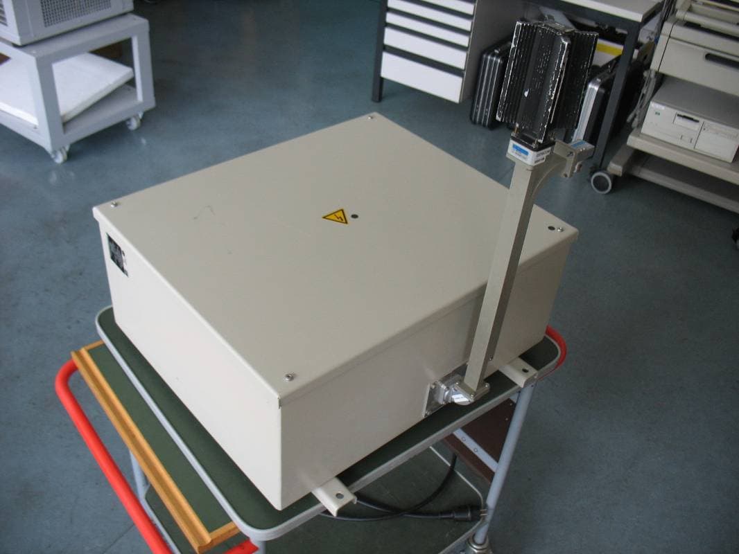
QO7NG3050X12-5KW
Nov 27, 2011RADARPILOT Platinum
Equipment Class
MRD - Marine Radar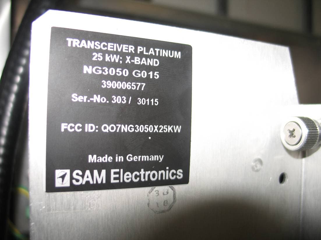
QO7NG3050X25KW
Nov 27, 2011RADARPILOT Platinum
Equipment Class
MRD - Marine Radar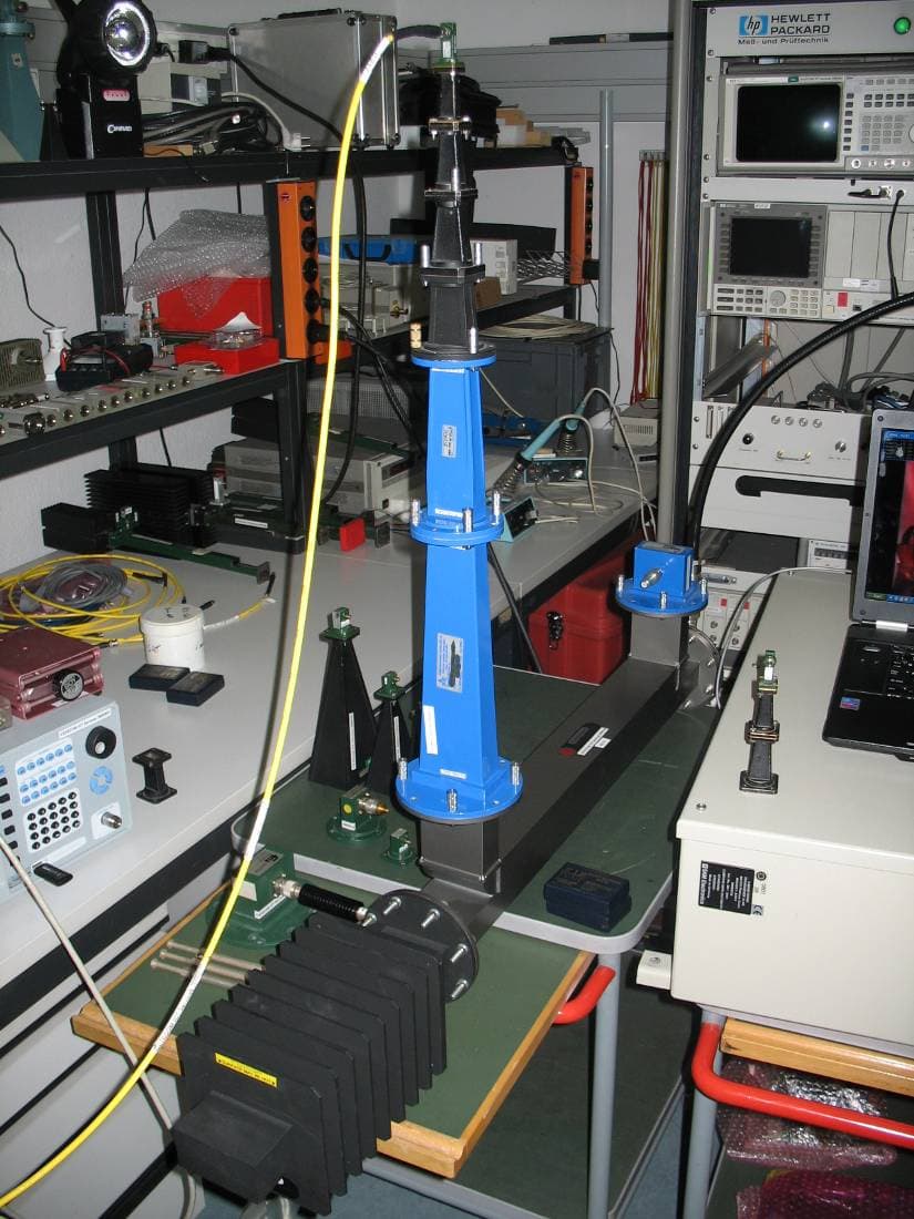
QO7NG3051S30KW
Nov 27, 2011RADARPILOT Platinum
Equipment Class
MRD - Marine Radar
QO7340X-RIK-93XX
May 01, 2003Automatic Identification System
Equipment Class
AIS - Automatic Identification Systems
QO7NG3028X25KW
Jan 13, 2003Marine Radar
Equipment Class
MRD - Marine Radar