QO7NG3050X12-5KWRADARPILOT Platinum
SAM Electronics GmbH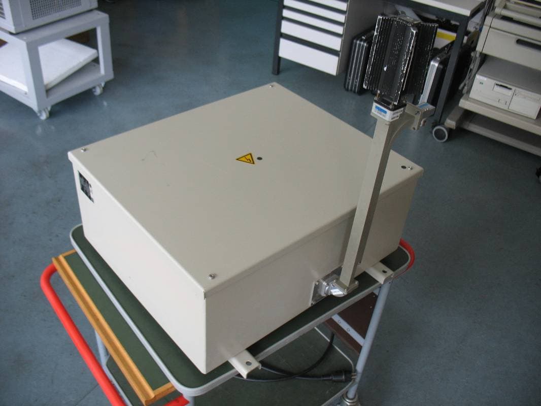
Click to zoom
Application Details
- Equipment Class
- MRD - Marine Radar
- Date of Grant
- Nov 27, 2011
- Application Purpose
- Original Equipment
- Date of Application
- Nov 27, 2011
- Equipment Note
- RADARPILOT Platinum
- Frequency Range
- 9300.00000000 - 9500.00000000
- Company
- SAM Electronics GmbH
- Country
- Germany
Documents & Files
Document Text
Text extracted from the exhibit documents filed with the FCC. Open a document above to read the original.
Users Manual
Operating Instructions NACOS Platinum Software Version 1.0 RADARPILOT Platinum RADARPILOT (with transceiver NG 3050 / NG 3051) CONNINGPILOT Item No.: ED 3100 G 130Revision: 03 (2011-08)Order No.:390008509 © SAM Electronics GmbH 2011 The reproduction, distribution, and utilization of this document as well as the communication of its content to others without explicit authorization is prohibited. Offenders will be held liable for the payment of damages. All rights reserved in the event of the grant of a patent, utility model, or design. Alterations due to technical progress are reserved. SAM Electronics GmbH D - 22763 Hamburg Service Customer Support Center Phone: + 49 (0) 18 03 00 85 53 Fax:+ 49 (0) 18 03 00 85 54 E-mail: [email protected] The radar transceivers of this NACOS Platinum system are FCC registered as follows: X-Band 12.5 KW:Q07NG3050X12-5KW X-Band 25 KW:Q07NG3050X25KW S-Band 30 KW:Q07NG3051S30KW For these units the following notes about FCC approval apply: NOTE: This equipment has been tested and found to comply with the limits for a Class A digital device, pursuant to Part 15 of the FCC Rules. These limits are designed to provide reasonable protection against harmful interference when the equipment is operated in a commercial environment. This equipment generates, uses, and can radiate radio frequency energy and, if not installed and used in accordance with the instruction manual, may cause harmful interference to radio communications. Operation of this equip- ment in a residential area is likely to cause harmful interference in which case the user will be required to correct the interference at his own expense. NOTICE: This device complies with Part 15 of the FCC Rules. Operation is subject to the following two conditions: (1)this device may not cause harmful interference, and (2)this device must accept any interference received, including interference that may cause undesired operation. NOTICE: Changes or modifications made to this equipment not expressly approved by SAM Electronics GmbH in Hamburg may void the FCC authorization to operate this equipment. Radiofrequency radiation exposure information: This equipment complies with FCC radiation exposure limits set forth for an uncontrolled environment. This equipment should be installed and operated with minimum distance of 21 m between the radiator and your body (30 KW S-Band Radar). For more details (i.e. X-Band and various antennas and trans- mitting power) please refer to section A chapter 1.1.2 in this manual. This transmitter must not be co-located or operating in conjunction with any other antenna or trans- mitter. ED 3100 G 140 / 04 (2011-11) Operating Instructions List of Contents OI_ANC2010_TOC.fm /10.11.2011 3 NACOS Platinum List of Contents IGENERAL . . . . . . . . . . . . . . . . . . . . . . . . . . . . . . . . . . . I - 1 1About these Operating Instructions . . . . . . . . . . . . . . . . . . . . . I - 3 1.1Aim and Scope of these Operating Instructions . . . . . . . . . . . . . . . . . . I - 4 1.2Validity of these Operating Instructions . . . . . . . . . . . . . . . . . . . . . . . . I - 5 1.3Availability of these Operating Instructions . . . . . . . . . . . . . . . . . . . . . I - 6 1.4How to Find Information in the Operating Instructions . . . . . . . . . . . . . I - 7 1.4.1Structure of the Operating Instructions . . . . . . . . . . . . . . . . . . . . . . . . I - 8 1.4.2How to find Information on Specific Subjects . . . . . . . . . . . . . . . . . . . . I - 9 1.5Typographical Conventions . . . . . . . . . . . . . . . . . . . . . . . . . . . . . . . I - 10 2Safety Precautions . . . . . . . . . . . . . . . . . . . . . . . . . . . . . . . . I - 13 2.1Warnings and Notes in these Operating Instructions . . . . . . . . . . . . . . I - 14 2.2Meaning of Safety Signs . . . . . . . . . . . . . . . . . . . . . . . . . . . . . . . . . . I - 15 2.3General Safety Notes – NACOS Platinum . . . . . . . . . . . . . . . . . . . . . . I - 17 2.4Authorisation and Qualification of Personnel . . . . . . . . . . . . . . . . . . . I - 18 2.5Commissioning . . . . . . . . . . . . . . . . . . . . . . . . . . . . . . . . . . . . . . . . I - 19 2.6Obligatory Safety Inspection . . . . . . . . . . . . . . . . . . . . . . . . . . . . . . I - 20 3NACOS Platinum System Description . . . . . . . . . . . . . . . . . . . I - 21 3.1What is the NACOS Platinum? . . . . . . . . . . . . . . . . . . . . . . . . . . . . . I - 22 3.2Customisation . . . . . . . . . . . . . . . . . . . . . . . . . . . . . . . . . . . . . . . . . I - 23 3.3Applicable Standards . . . . . . . . . . . . . . . . . . . . . . . . . . . . . . . . . . . . I - 25 4Multi Function Display . . . . . . . . . . . . . . . . . . . . . . . . . . . . . I - 27 4.1General System Description MFD . . . . . . . . . . . . . . . . . . . . . . . . . . . I - 28 4.2Operating Devices . . . . . . . . . . . . . . . . . . . . . . . . . . . . . . . . . . . . . . I - 29 4.2.1Pointing Devices – Trackball and Mouse . . . . . . . . . . . . . . . . . . . . . . I - 30 4.2.2Keyboard . . . . . . . . . . . . . . . . . . . . . . . . . . . . . . . . . . . . . . . . . . . . I - 32 4.2.3The ASCII Keyboard . . . . . . . . . . . . . . . . . . . . . . . . . . . . . . . . . . . . I - 33 4.2.4The RADAR Keyboard . . . . . . . . . . . . . . . . . . . . . . . . . . . . . . . . . . . I - 34 4.2.5The TRACKPILOT Keyboard . . . . . . . . . . . . . . . . . . . . . . . . . . . . . . . I - 35 4.3TFT Monitor . . . . . . . . . . . . . . . . . . . . . . . . . . . . . . . . . . . . . . . . . . I - 36 4.3.1Nominal Viewing Distance . . . . . . . . . . . . . . . . . . . . . . . . . . . . . . . . I - 37 4.3.2Colour Distortions on Monitors with Flat Screens (TFT Monitors) . . . . . I - 38 4.3.3Printers . . . . . . . . . . . . . . . . . . . . . . . . . . . . . . . . . . . . . . . . . . . . . I - 39 4.4Startup and Shutdown of MFDs . . . . . . . . . . . . . . . . . . . . . . . . . . . . I - 40 4.5Basic Settings . . . . . . . . . .…
Text truncated - open the document above for the full version.
External Photos
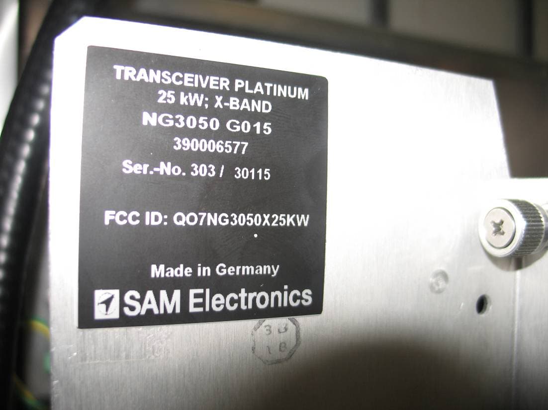
Test report no.: 1-3171-01-02/11 2011-09-23 Page 99 of 113 Annex E: External photographs of the EUT Photo No. 1: Photo No. 2: Test report no.: 1-3171-01-02/11 2011-09-23 Page 100 of 113 Photo No. 3: type label
Test Report
2011-09-23 Page 1 of 113 TEST REPORT Test report no.: 1-3171-01-02/11 Testing laboratory Applicant CETECOM ICT Services GmbH Untertuerkheimer Strasse 6 - 10 66117 Saarbruecken / Germany Phone: + 49 681 5 98 - 0 Fax: + 49 681 5 98 - 9075 Internet: http://www.cetecom.com e-mail: [email protected] Accredited test laboratory: The test laboratory (area of testing) is accredited according to DIN EN ISO/IEC 17025 DAkkS registration number: D-PL-12076-01-01 Area of Testing: Radio/Satellite Communications SAM Electronics GmbH Behringstrasse 120 D-22763 Hamburg / Germany Contact: Mr. Karl-Christian Ehrke e-mail: [email protected] Phone: +49 40 8825 2868 Manufacturer SAM Electronics GmbH Behringstrasse 120 D-22763 Hamburg / Germany Test standard/s 47 CFR Part 80 Title 47 of the Code of Federal Regulations; Chapter I Part 80 - Stations in the maritime services For further applied test standards please refer to section 4 of this test report. Test item Kind of test item: Shipborne radar - X-Band transceiver Model name: NG3050 12.5 kW FCC ID: QO7NG3050X12-5KW Frequency band: 9.3 - 9.5 GHz Power supply: 115 / 230 V AC Temperature range: -25 °C to +55 °C Test performed: Test report authorised: 2011-09-23 Meheza Walla 2011-09-23 Karsten Geraldy Test report no.: 1-3171-01-02/11 2011-09-23 Page 2 of 113 1 Table of contents 1 Table of contents............................................................................................................................................2 2 General information .......................................................................................................................................3 2.1 Notes.....................................................................................................................................................3 2.2 Application details...............................................................................................................................3 2.3 Test environment.................................................................................................................................3 2.4 Test laboratories sub-contracted ......................................................................................................3 3 Test item (EUT) ...............................................................................................................................................4 3.1 General Description ............................................................................................................................4 3.2 List of components .............................................................................................................................4 3.3 Operating conditions ..........................................................................................................................4 3.4 Additional information ........................................................................................................................4 4 Test standard/s ...............................................................................................................................................5 5 Measurement and test setup, measurement uncertainties........................................................................6 5.1 Radiated measurements .....................................................................................................................6 5.2 Conducted measurements .................................................................................................................7 6 Test results .....................................................................................................................................................9 6.1 Summary ..............................................................................................................................................9 6.2 Overview.............................................................................................................................................10 Annex A: Measurement results, part 1 ..............................................................................................................18 Annex B: Measurement results, part 2 ..............................................................................................................87 Annex C: Test equipment and ancillaries used for tests ................................................................................93 Annex D: Photographs of the test setup...........................................................................................................96 Annex E: External photographs of the EUT......................................................................................................99 Annex F: Internal photographs of the EUT .....................................................................................................101 Annex G: Document history .............................................................................................................................113 Annex H: Further information ..........................................................................................................................113 Test report no.: 1-3171-01-02/11 2011-09-23 Page 3 of 113 2 General information 2.1 Notes The test results of this test report relate exclusively to the test item specified in this test report. CETECOM ICT Services GmbH does not assume responsibility for any conclusions and generalisations drawn from the test results with regard to other specimens or samples of the type of the equipment represented by the test item. The test report may only be reproduced or published in full. Reproduction or publication of extracts from the report requires the prior written approval of CETECOM ICT Services GmbH. 2.2 Application details Date of receipt of order: 2011-05-17 Date of receipt of test item: 2011-07-12 Start of test: 2011-0…
Text truncated - open the document above for the full version.
Test Setup Photos
Test report no.: 1-3171-01-02/11 2011-09-23 Page 96 of 113 Annex D: Photographs of the test setup Photo No. 1: radiated spurious emissions up to 12 GHz Photo No. 2: radiated spurious emissions up to 12 GHz Test report no.: 1-3171-01-02/11 2011-09-23 Page 97 of 113 Photo No. 3: conducted measurements, spurious emissions (with stub tuner) Test report no.: 1-3171-01-02/11 2011-09-23 Page 98 of 113 Photo No. 4: conducted measurements, spurious emissions > 15 GHz Photo No. 5: conducted measurements, spurious emissions up to 40 GHz
Contact Information
Applicant
Karl-Christian Ehrke(Dipl.-Ing.)
Test Firm
cetecom advanced GmbHGerald Schmidt
Technical Specifications
| # | Rule Parts | Frequency Range | Power Output | Emission | Tolerance |
|---|---|---|---|---|---|
| 1 | 80 | 9.30 GHz - 9.50 GHz | 12500 W | 91M0P0N | 0.0800000000 % |
Other Applications from SAM Electronics GmbH
QO7NG3050X25KW
Nov 27, 2011RADARPILOT Platinum
Equipment Class
MRD - Marine Radar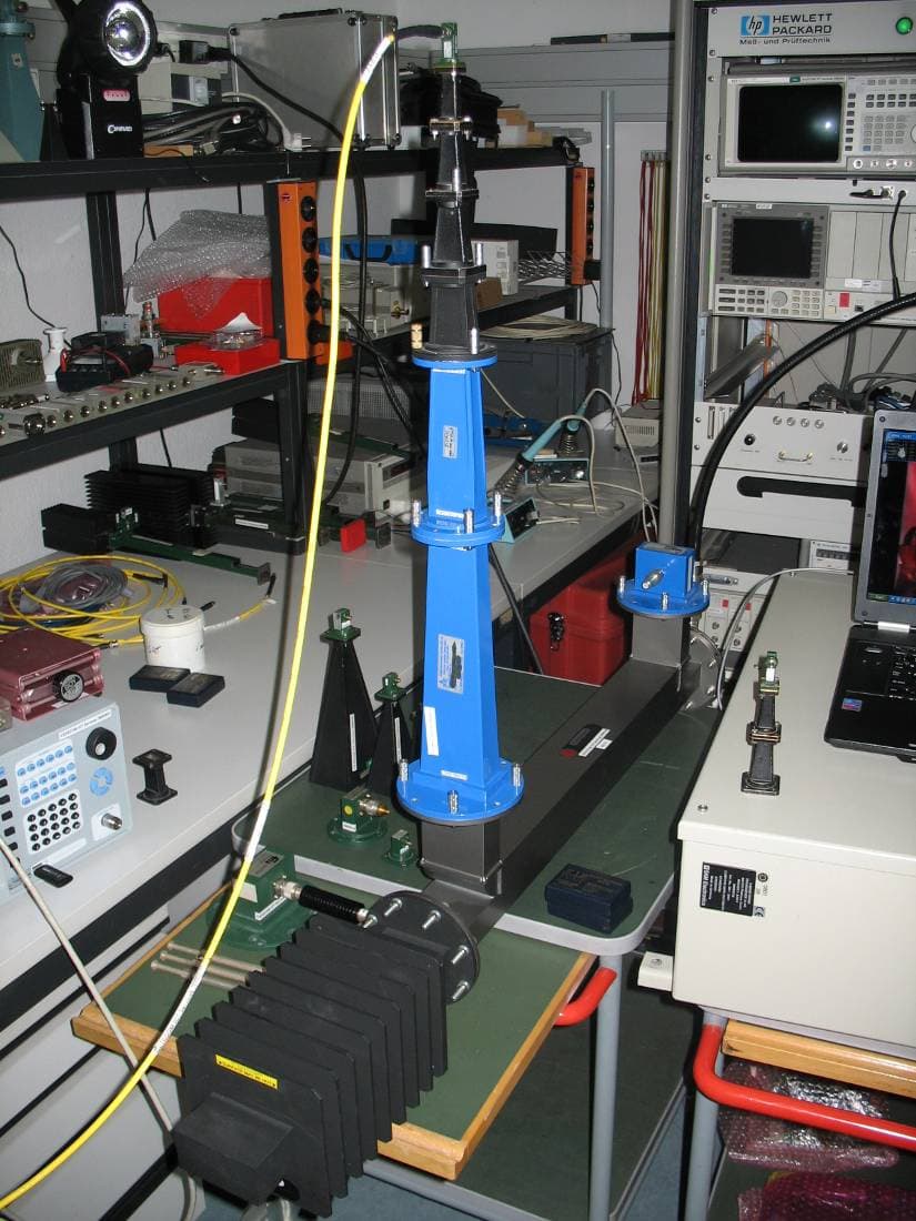
QO7NG3051S30KW
Nov 27, 2011RADARPILOT Platinum
Equipment Class
MRD - Marine Radar
QO7AIS3410
Jul 04, 2010Maritime AIS Transponder
Equipment Class
AIS - Automatic Identification Systems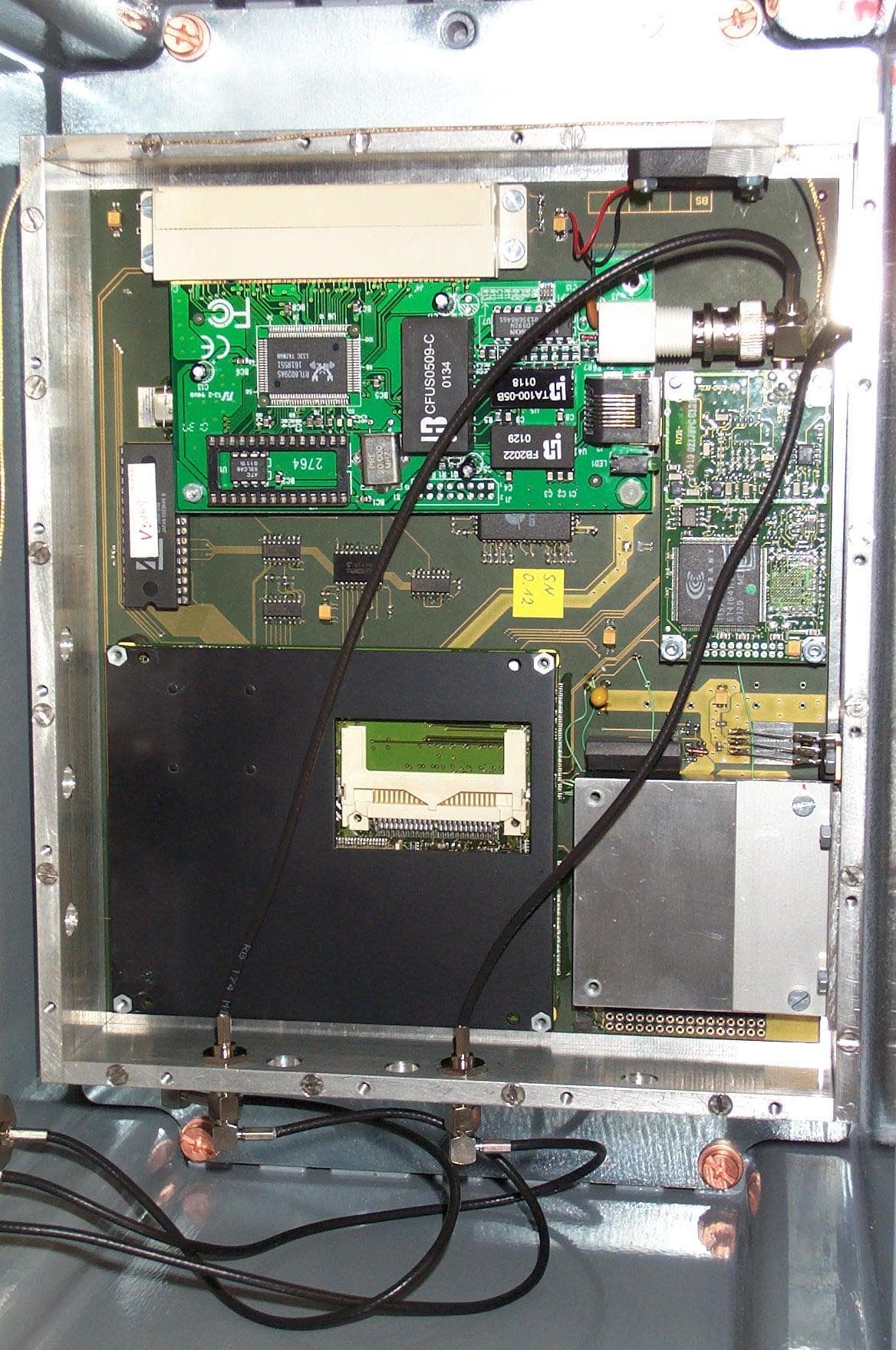
QO7340X-RIK-93XX
May 01, 2003Automatic Identification System
Equipment Class
AIS - Automatic Identification Systems
QO7NG3028X25KW
Jan 13, 2003Marine Radar
Equipment Class
MRD - Marine Radar