QONBRN5000BeamPlex Base Station Indoor Unit
BeamReach Networks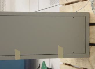
Click to zoom
Application Details
- Equipment Class
- TNB - Licensed Non-Broadcast Station Transmitter
- Date of Grant
- Nov 22, 2003
- Application Purpose
- Original Equipment
- Date of Application
- Nov 22, 2003
- Equipment Note
- BeamPlex Base Station Indoor Unit
- Frequency Range
- 2355.00000000 - 2360.00000000
- Company
- BeamReach Networks
- Country
- United States
Documents & Files
Document Text
Text extracted from the exhibit documents filed with the FCC. Open a document above to read the original.
Cover Letter(s)
December 3, 2003 Federal Communications Commission Authorization and Evaluation Division 7435 Oakland Mills Road Columbia, MD 21046 Re: Request for confidentiality Applicant: BeamReach Networks Inc. FCC ID: QONBRN5000 To whom it may concern, Request is hereby submitted by BeamReach Networks to withhold from public review certain portions of the application for equipment certification for FCC identifier QONBRN5000. This request for confidentiality is made pursuant to 47 CFR 0.459 of the FCC Rules. BeamReach Networks is a start-up company in the highly competitive, fixed broadband wireless market where product pricing is very dynamic and where our products incorporate new, state-of-the-art technologies as a competitive advantage. Disclosure of these technologies or pricing associated with these technologies could be damaging to our competitive position within this market. Specific documents for which we request protection from public disclosure include: the RF block diagram providing RF, IF and baseband frequencies of operation, schematics detailing the circuits used in the products, bills of materials detailing the components used in assemblies of the products, the Digital Modulation description document which describes the digital modulation used in the products, the base tune-up procedure, specification control documents (SCDs) that include the specifications for custom components developed by BeamReach for the products, base station installation and commissioning manual. If there are questions or issues regarding this request, I can be reached by phone at (508) 869-8707 or e-mail at [email protected]. Anthony Tokuno Director, Hardware Engineering BeamReach Networks Inc.
Internal Photos
Page 1 of 15 Photograph 1. Cavity Filter Photograph 2. DS3 and OC3 NPC Top Page 2 of 15 Photograph 3. DS3 and OC3 NPC Bottom Photograph 4. Fan Tray Top Page 3 of 15 Photograph 5. Fan Tray Bottom Photograph 6. Fast Ethernet NPC Top Page 4 of 15 Photograph 7. Fast Ethernet NPC Bottom Photograph 8. LO Top Page 5 of 15 Photograph 9. LO Bottom Photograph 10. LO Top without Shield Cover Page 6 of 15 Photograph 11. MBP Top Photograph 12. MBP Bottom Page 7 of 15 Photograph 13. MTM Top Photograph 14. MTM Bottom Page 8 of 15 Photograph 15. PM P Open Cover Photograph 16. PM Close Cover Page 9 of 15 Photograph 17. PM Side PC Board Photograph 18. PM without Heat Sink Page 10 of 15 Photograph 19. PRBD Top Photograph 20. PRBD Bottom Page 11 of 15 Photograph 21. PRBT Top Photograph 22. PRBT Bottom Page 12 of 15 Photograph 23. RFSW Top Photograph 24. RFSW Bottom Page 13 of 15 Photograph 25. Trimble GPS Module Photograph 26. XCVR Top Page 14 of 15 Photograph 27. XCVR Bottom Photograph 28. XCVR Top without Shield Cover Page 15 of 15 Photograph 29. XCVR Bottom without Shield Cover
Internal Photos
Figure 1. LO Module with shields removed. Figure 2. Quad Transceiver Module with shields removed. Figure 3. Power Module with power amp heat sink removed, left oblique view. Figure 4. Power Module with power amp heat sink removed, right oblique view.
Test Report
Figure 1. Frequency Stability Test Set-up – Complete View Figure 2. Frequency Stability Test Set-up – close-up of DUT Figure 3. Frequency Stability Test Set-up – close-up of Test Equipment Figure 4. Frequency Stability Test Set-up – temperature chamber door closed Page 1 of 4 9/4/03 Beamreach Base Station Frequency Stability Test Date: 9/4/03 Tested by: Steve Lin Test Description: The frequency stability of the Beamreach base station is set by a GPS time/frequency standard. This unit provides a 10MHz output that has been locked to the frequency references onboard the GPS satellites. The local oscillators within the base station are then locked to this very stable reference frequency. The frequency vs temperature stability of the Beamreach base station was measured by putting the LO reference and LO generation circuitry in a temperature chamber, running them over the temperature range and measuring the frequency of the LO output. The required components of the base station consisted of the GPS time/frequency standard and the LO module. A spectrum analyzer was used to measure the output frequency of the LO. Hardware Tested: LO module S/N 007; and Starloc II GPS module manufactured by Datum Corporation (now Symmetricom). Test Results: Temperature (deg C) Measured LO Frequency (Hz) Frequency Error (Hz) -20 1,960,000,000 0 -10 1,959,999,994 -6 0 1,959,999,997 -3 10 1,959,999,994 -6 20 1,959,999,997 -3 30 1,959,999,997 -3 40 1,959,999,994 -6 50 1,959,999,994 -6 60 1,959,999,994 -6 The LO was tuned to a center frequency of 1.96GHz. The test data shows that the worst case frequency deviation was 6Hz. FCC part 27.54 states that the frequency stability shall be sufficient to ensure that the fundamental emissions stay within the authorized bands of operation. The emission bandwidth is 3.75MHz within the 5MHz band resulting in 625kHz guard bands between the emissions and the band edges. The 6Hz frequency deviation over temperature is a very small number compared to the 625kHz guard band, ensuring that the FCC specification is met. Test Data: The complete set of test data, including the GPS unit status is given below. Page 2 of 4 9/4/03 Temp Measured LO Frequency GPS Unit Status -20°C 1,960,000,000 Hz -10°C 1,959,999,994 Hz 0°C 1,959,999,997 Hz Page 3 of 4 9/4/03 Temp Measured LO Frequency GPS Unit Status 10°C 1,959,999,994 Hz 20°C 1,959,999,997 Hz 30°C 1,959,999,997 Hz Page 4 of 4 9/4/03 Temp Measured LO Frequency GPS Unit Status 40°C 1,959,999,994 Hz 50°C 1,959,999,994 Hz 60°C 1,959,999,994 Hz
Test Report
Page 1 of 4 9/4/03 Beamreach Base Station Frequency Stability Test Date: 10/16/03, Tested by: Steve Lin Test Description: The frequency stability of the Beamreach base station is set by a GPS time/frequency standard. This unit provides a 10MHz output that has been locked to the frequency references onboard the GPS satellites. The local oscillators within the base station are then locked to this very stable reference frequency. The frequency vs temperature stability of the Beamreach base station was measured by putting the LO reference and LO generation circuitry in a temperature chamber, running them over the temperature range and measuring the frequency of the LO output. The required components of the base station consisted of the GPS time/frequency standard and the LO module. A spectrum analyzer was used to measure the output frequency of the LO. Hardware Tested: LO module S/N 007; and Starloc II GPS module manufactured by Datum Corporation (now Symmetricom). Test Equipments: Spectrum Analyzer, HP 8562E & HP8595E, cal due 4/30/04 Power Supply, Topward 66030-10, no calibration required Test Results: Temperature (deg C) Measured LO Frequency (Hz) Frequency Error (Hz) -20 1,960,000,000 0 -10 1,959,999,994 -6 0 1,959,999,997 -3 10 1,959,999,994 -6 20 1,959,999,997 -3 30 1,959,999,997 -3 40 1,959,999,994 -6 50 1,959,999,994 -6 60 1,959,999,994 -6 The LO was tuned to a center frequency of 1.96GHz. The test data shows that the worst case frequency deviation was 6Hz. FCC part 27.54 states that the frequency stability shall be sufficient to ensure that the fundamental emissions stay within the authorized bands of operation. The emission bandwidth is 3.75MHz within the 5MHz band resulting in 625kHz guard bands between the emissions and the band edges. The 6Hz frequency deviation over temperature is a very small number compared to the 625kHz guard band, ensuring that the FCC specification is met. Test Data: The complete set of test data, including the GPS unit status is given below. Page 2 of 4 9/4/03 Temp Measured LO Frequency GPS Unit Status -20°C 1,960,000,000 Hz -10°C 1,959,999,994 Hz 0°C 1,959,999,997 Hz Page 3 of 4 9/4/03 Temp Measured LO Frequency GPS Unit Status 10°C 1,959,999,994 Hz 20°C 1,959,999,997 Hz 30°C 1,959,999,997 Hz Page 4 of 4 9/4/03 Temp Measured LO Frequency GPS Unit Status 40°C 1,959,999,994 Hz 50°C 1,959,999,994 Hz 60°C 1,959,999,994 Hz
Test Report
BEAMREACH NETWORKS MODIFICATIONS MADE TO THE BRN5000 BASESTATION FOR FCC COMPLIANCE SEPTEMBER 29, 2003 The following is a list of the modifications that were required to the BeamReach BRN5000 basestation hardware in order to comply with FCC regulations per FCC CFR47 Part 15 and Part 27. 1. Added an aluminum shroud over the bottom rear portion of the main rack to reduce radiated emissions. This shroud covers the rear of the fan tray assembly, the 9U backplane assembly and the 4U backplane assembly, with cabling either routed out through the shroud or terminated with connections on the shroud. 2. Added absorber material to the rear of the shroud to reduce radiated emissions. Material is ETS- Lindgren PN FL-1125CL. This is a flat laminate absorber made from three layers of carbon- impregnated foam with a thickness of 2.9 cm. The reflection coefficient of this absorber is guaranteed to be –20 dB or less at 3.0 GHz. 3. Added 5 ferrites on cables at exit from shroud. 4. Added shielding to the Fast Ethernet and DS-3 cables between the 9U backplane and the top of the rack. 5. Modified the LO primary and redundant modules to enable or disable the LO outputs when not being used. 6. Routing of coax cabling on the LO Module was modified, with 6 cables now routed on the topside of the board connected between the right angle edge connector and right angle PCB-mounted connectors. BASE CONFIGURATION TESTED 1. The base was configured for 8 antenna, 3 subband pair, redundant WCS operation, which is the highest total output power of the configurations to be included in the base certification. Other configurations to be included in this certification are: 8 antenna, 1 subband pair redundant 8 antenna, 2 subband pair redundant 6 antenna, 1 subband pair redundant 6 antenna, 2 subband pair redundant 6 antenna, 3 subband pair redundant all previously mentioned configurations but with non-redundant hardware for a total of 12 different configurations. 2. WCS bands tested included A and B but not C or D. 3. Backhaul interfaces tested included ATM over OC-3, ATM over DS3 and IP over 100baseT. 4. Power amps used were 10 watt versions.
Test Report
The Nation's First Licensed Nationally Recognized Testing Laboratory Conceil canadien des nomes Organi sme de certi fi cat i on accedi t e St andar ds Counci l of Canada Accredi ted Cert ifi cati on Organizat ion TM MET Laboratories, Inc. Safety Certification - EMI - Telecom Environmental Simulation 33439 WESTERN AVENUE ! UNION CITY, CALIFORNIA 94587-3201 ! PHONE (510) 489-6300 ! FAX (510) 489-6372 November 10, 2003 BeamReach Networks 755 North Mathilda Avenue Sunnyvale, CA 94086 Reference:BRN-5000 with WCSA and WCSB Dear Mr. Tony Tokuno, Enclosed is the EMC Test Report for the BeamReach Networks, BRN-5000 with WCSA and WCSB tested to the requirements of the FCC Rules and Regulations, Part 27 Subpart C, of Title 47 of the CFR, for a Miscellaneous Wireless Communications Services. Thank you for using the testing services of MET Laboratories. If you have any questions regarding these results or if MET can be of further assistance to you, please feel free to contact me. We appreciate your business and look forward to working with you again soon. Kindest Regards, MET LABORATORIES, INC. Cheryl Anicete Documentation Department Enclosures: (\BeamReach Networks\EMCS13860-FCC27.rpt) DOCTEM-23 Jan 02 Certificates and reports shall not be reproduced except in full, without the written permission of MET Laboratories, Inc. While use of the National Voluntary Laboratory Accreditation Program (NVLAP) letters or the NVLAP Logo, the Standards Council of Canada Logo, or the Nationally Recognized Testing Laboratory (NRTL) Letters in this report reflects MET Accreditation under these programs, these letters, logo, or statements do not claim product endorsement by NVLAP or any Agency of the U.S. Government. This letter of transmittal is not a part of the attached report. BeamReach NetworksBRN-5000 with WCSA and WCSB November 10, 2003 Electro-Magnetic Compatibility Test Report for the BeamReach Networks BRN-5000 with WCSA and WCSB Tested Under FCC Part 27, Subpart C Title 47 of the CFR for Miscellaneous Wireless Communications Services MET REPORT: EMCS13860-FCC27 November 10, 2003 PREPARED FOR: BeamReach Networks 755 North Mathilda Avenue Sunnyvale, CA 94086 PREPARED BY: MET Laboratories, Inc. 33439 Western Avenue Union City, California 94587 Copyright 2003, MET Laboratories, Inc. This report shall not be reproduced except in full, without the express written consent of MET Laboratories, Inc., nor shall this report, or any copy thereof be provided to a competitor of MET Laboratories, Inc. BeamReach NetworksBRN-5000 with WCSA and WCSB November 10, 2003 MET# EMCS13860-FCC27Copyright 2003, MET Laboratories, Inc.Page i of vi Electro-Magnetic Compatibility Test Report for the BeamReach Networks BRN-5000 with WCSA and WCSB Tested Under FCC Part 27, Subpart C Title 47 of the CFR for Miscellaneous Wireless Communications Services MET REPORT: EMCS13860-FCC27 PREPARED FOR: BeamReach Networks 755 North Mathilda Avenue Sunnyvale, CA 94086 _______________________________ Alvin Ilarina, Manager Electromagnetic Compatibility Testing _______________________________ Cheryl Anicete Documentation Department Engineering Statement: The measurements shown in this report were made in accordance with the procedures indicated, and the emissions from this equipment were found to be within the limits applicable. I assume full responsibility for the accuracy and completeness of these measurements, and for the qualifications of all persons taking them.. It is further stated that upon the basis of the measurements made, the equipment tested is capable of operation in accordance with the requirements of Part 27, Subpart C, of the FCC Rules under normal use and maintenance. _______________________________ Kerwinn Corpuz Project Engineer BeamReach NetworksBRN-5000 with WCSA and WCSB November 10, 2003 MET# EMCS13860-FCC27Copyright 2003, MET Laboratories, Inc.Page ii of vi REPORT STATUS SHEET RevisionReport/Revision DateReason for Revision iNovember 10, 2003 Initial Issue . BeamReach NetworksBRN-5000 with WCSA and WCSB November 10, 2003 MET# EMCS13860-FCC27Copyright 2003, MET Laboratories, Inc.Page iii of vi TABLE OF CONTENTS I.Executive Summary ...........................................................................1 A.Purpose of Test .......................................................................2 B.Executive Summary ....................................................................2 II.General.....................................................................................3 A.Test Site .............................................................................4 B.Description of Test Sample ..............................................................4 C.Emission Designator Description..........................................................4 D.General Test Setup.....................................................................5 E.Mode of Operation.....................................................................5 F.Modification ........................................................................11 G.Disposition of Test Sample.............................................................11 III.Electromagnetic Compatibility RF Power Output Requirements........................................12 A.RF Power Output .....................................................................13 IV.Electromagnetic Compatibility Modulation Characteristics Requirements................................15 A.Modulation Characteristics .............................................................16 V.Electromagnetic Compatibility Occupied Bandwidth Requirements.....................................17 A.Occupied Bandwidth ..................................................................18 VI.Electromagnetic Compatibility Emissions Requirements..............................................22 A.Spurious Emissions at Antenna Terminals..................................................23 B.Radiated Emissions (Substitution Method)..........…
Text truncated - open the document above for the full version.
Test Report
Chris Harvey EMC From: Chris Harvey EMC [[email protected]] Sent: Monday, November 17, 2003 3:21 PM To: Marianne Bosley ([email protected]) Cc: 'Alvin Ilarina' Subject: BeamReach FCC Application review comments, Request for Technical Information Page 1 of 1 11/17/2003 The following items must be corrected before this application can continue to be reviewed for FCC Compliance: 1) The photos submitted do not show back sides of boards, and the front side photos are out of focus (Base Module Photos). Please resubmit corrected photographs. 2) Please provide an Emission Designator. 3) Please submit a Label location drawing. 4) Please correct the following items in the test report: Equipment code is TNB; Emission Designator; Mode of Operation; Modifications section details from the applicant. 5) Report Section A Spurious Emissions at Antenna Terminals, per 27.53 (a)(4) the bandwidth used is supposed to be 1MHz or greater. The report seems to document a Resolution Bandwidth of 100 kHz in each plot. This needs to be corrected. 6) Report Section major headers and then the next header do not match (i.e. Test Equipment section VIII vs. VI.) Please reply as soon as possible so that the application review can be completed. Best regards, Chris Harvey Chris Harvey EMC Consultants, LLC cell 443-622-3300
Test Report
Chris Harvey EMC From: [email protected] Sent: Friday, November 21, 2003 5:05 PM To: [email protected] Cc: [email protected]; [email protected]; [email protected]; [email protected]; [email protected] Subject: RE: BeamReach FCC Application review comments, Request for Technical Information Page 1 of 3 11/23/2003 Hi Chris, Here are the updated FCC27 report and internal photos. As for questions below, please see questions and below it are answers, in red font, to each questions. Best Regards, Kerwinn -----Original Message----- From: Marianne Bosley Sent: Monday, November 17, 2003 12:47 PM To: Kerwinn Corpuz Cc: Gaylon Morris; '[email protected]' Subject: FW: BeamReach FCC Application review comments, Request for Technical Information Importance: High Hi Kerwin, Please attend to the technical issues below. I already told Chris that I had told you to send report without emission designator, and I guess I told you the wrong equipment type code? I asked Chris to forward some help with the emission designator, and I can contact Tony for the label location. But the rest is technical. Let me know if I can do anything and please carbon me on your response to Chris. Thanks. Marianne -----Original Message----- From: Chris Harvey EMC To: 'Marianne Bosley' Sent: 11/17/2003 3:36 PM Subject: FW: BeamReach FCC Application review comments, Request for Technical Information Chris Harvey Chris Harvey EMC Consultants, LLC cell 443-622-3300 -----Original Message----- From: Chris Harvey EMC [mailto:[email protected]] Sent: Monday, November 17, 2003 3:21 PM To: Marianne Bosley ([email protected]) Cc: 'Alvin Ilarina' Subject: BeamReach FCC Application review comments, Request for Technical Information The following items must be corrected before this application can continue to be reviewed for FCC Compliance: 1) The photos submitted do not show back sides of boards, and the front side photos are out of focus (Base Module Photos). Please resubmit corrected photographs. Updated, please see Internal Photos attached file. 2) Please provide an Emission Designator. Updated, please see section Table 1 of FCC27 report. 3) Please submit a Label location drawing. I guess Marianne have updated with you on one. 4) Please correct the following items in the test report: Equipment code is TNB; Emission Designator; Mode of Operation; Modifications section details from the applicant. 1) Equipment Code: updated Table 1 of FCC27 report. 2) Emission Designator: please see Table 1 of FCC27 report and see page 4 of 49 for explanation. 3) Mode of Operation: updated FCC27 report, see page 5 of 49. 4) Modification: updated, please see FCC27 report page 11 of 49. 5) Report Section A Spurious Emissions at Antenna Terminals, per 27.53 (a)(4) the bandwidth used is supposed to be 1MHz or greater. The report seems to document a Resolution Bandwidth of 100 kHz in each plot. This needs to be corrected. Section 27(a)(4) .....employing a resolution bandwidth of 1MHz or less, but at least one percent of the emission bandwidth of the fundamental emission of the transmitter. I used one percent of the fundamental because the noise floor is to high when resolution BW is set to 1MHz and it will not pass the 50 dBc limit. Fundamental BW measured = 4 MHz * 1% = 40kHz, therefore 100kHz was use on the resolution BW. 6) Report Section major headers and then the next header do not match (i.e. Test Equipment section VIII vs. VI.) Correction complete. Please reply as soon as possible so that the application review can be Page 2 of 3 11/23/2003 completed. Best regards, Chris Harvey Chris Harvey EMC Consultants, LLC cell 443-622-3300 Page 3 of 3 11/23/2003
Test Report
The Nation's First Licensed Nationally Recognized Testing Laboratory Conceil canadien des nomes Organi sme de certi fi cat i on accedi t e St andar ds Counci l of Canada Accredi ted Cert ifi cati on Organizat ion TM MET Laboratories, Inc. Safety Certification - EMI - Telecom Environmental Simulation 33439 WESTERN AVENUE ! UNION CITY, CALIFORNIA 94587-3201 ! PHONE (510) 489-6300 ! FAX (510) 489-6372 November 10, 2003 BeamReach Networks 755 North Mathilda Avenue Sunnyvale, CA 94086 Reference:BRN-5000 with WCSA and WCSB Dear Mr. Tony Tokuno, Enclosed is the EMC Test Report for the BeamReach Networks, BRN-5000 with WCSA and WCSB tested to the requirements of the FCC Rules and Regulations, Part 27 Subpart C, of Title 47 of the CFR, for a Miscellaneous Wireless Communications Services. Thank you for using the testing services of MET Laboratories. If you have any questions regarding these results or if MET can be of further assistance to you, please feel free to contact me. We appreciate your business and look forward to working with you again soon. Kindest Regards, MET LABORATORIES, INC. Cheryl Anicete Documentation Department Enclosures: (\BeamReach Networks\EMCS13860-FCC27.rpt) DOCTEM-23 Jan 02 Certificates and reports shall not be reproduced except in full, without the written permission of MET Laboratories, Inc. While use of the National Voluntary Laboratory Accreditation Program (NVLAP) letters or the NVLAP Logo, the Standards Council of Canada Logo, or the Nationally Recognized Testing Laboratory (NRTL) Letters in this report reflects MET Accreditation under these programs, these letters, logo, or statements do not claim product endorsement by NVLAP or any Agency of the U.S. Government. This letter of transmittal is not a part of the attached report. BeamReach NetworksBRN-5000 with WCSA and WCSB November 10, 2003 Electro-Magnetic Compatibility Test Report for the BeamReach Networks BRN-5000 with WCSA and WCSB Tested Under FCC Part 27, Subpart C Title 47 of the CFR for Miscellaneous Wireless Communications Services MET REPORT: EMCS13860-FCC27 November 10, 2003 PREPARED FOR: BeamReach Networks 755 North Mathilda Avenue Sunnyvale, CA 94086 PREPARED BY: MET Laboratories, Inc. 33439 Western Avenue Union City, California 94587 Copyright 2003, MET Laboratories, Inc. This report shall not be reproduced except in full, without the express written consent of MET Laboratories, Inc., nor shall this report, or any copy thereof be provided to a competitor of MET Laboratories, Inc. BeamReach NetworksBRN-5000 with WCSA and WCSB November 10, 2003 MET# EMCS13860-FCC27Copyright 2003, MET Laboratories, Inc.Page i of vi Electro-Magnetic Compatibility Test Report for the BeamReach Networks BRN-5000 with WCSA and WCSB Tested Under FCC Part 27, Subpart C Title 47 of the CFR for Miscellaneous Wireless Communications Services MET REPORT: EMCS13860-FCC27 PREPARED FOR: BeamReach Networks 755 North Mathilda Avenue Sunnyvale, CA 94086 _______________________________ Alvin Ilarina, Manager Electromagnetic Compatibility Testing _______________________________ Cheryl Anicete Documentation Department Engineering Statement: The measurements shown in this report were made in accordance with the procedures indicated, and the emissions from this equipment were found to be within the limits applicable. I assume full responsibility for the accuracy and completeness of these measurements, and for the qualifications of all persons taking them.. It is further stated that upon the basis of the measurements made, the equipment tested is capable of operation in accordance with the requirements of Part 27, Subpart C, of the FCC Rules under normal use and maintenance. _______________________________ Kerwinn Corpuz Project Engineer BeamReach NetworksBRN-5000 with WCSA and WCSB November 10, 2003 MET# EMCS13860-FCC27Copyright 2003, MET Laboratories, Inc.Page ii of vi REPORT STATUS SHEET RevisionReport/Revision DateReason for Revision iNovember 10, 2003 Initial Issue . BeamReach NetworksBRN-5000 with WCSA and WCSB November 10, 2003 MET# EMCS13860-FCC27Copyright 2003, MET Laboratories, Inc.Page iii of vi TABLE OF CONTENTS I.Executive Summary ...........................................................................1 A.Purpose of Test .......................................................................2 B.Executive Summary ....................................................................2 II.General.....................................................................................3 A.Test Site .............................................................................4 B.Description of Test Sample ..............................................................4 C.Emission Designator Description..........................................................4 D.General Test Setup.....................................................................5 E.Mode of Operation.....................................................................5 F.Modification ........................................................................11 G.Disposition of Test Sample.............................................................11 III.Electromagnetic Compatibility RF Power Output Requirements........................................12 A.RF Power Output .....................................................................13 IV.Electromagnetic Compatibility Modulation Characteristics Requirements................................15 A.Modulation Characteristics .............................................................16 V.Electromagnetic Compatibility Occupied Bandwidth Requirements.....................................17 A.Occupied Bandwidth ..................................................................18 VI.Electromagnetic Compatibility Emissions Requirements..............................................22 A.Spurious Emissions at Antenna Terminals..................................................23 B.Radiated Emissions (Substitution Method)..........…
Text truncated - open the document above for the full version.
Test Setup Photos
Figure 2. Frequency Stability Test Set-up – Complete View Figure 3. Frequency Stability Test Set-up – close-up of DUT Figure 4. Frequency Stability Test Set-up – close-up of Test Equipment Figure 5. Frequency Stability Test Set-up – temperature chamber door closed
Contact Information
Applicant
Anthony Tokuno(Director, Hardware Engineering)
Test Firm
MET Laboratories, Inc.Asad Bajwa
Technical Specifications
| # | Rule Parts | Frequency Range | Power Output | Emission | Tolerance |
|---|---|---|---|---|---|
| 4 | 27 | 2.35 GHz - 2.36 GHz | 4 W | 7M50D7D | 10 Hz |
Other Applications from BeamReach Networks
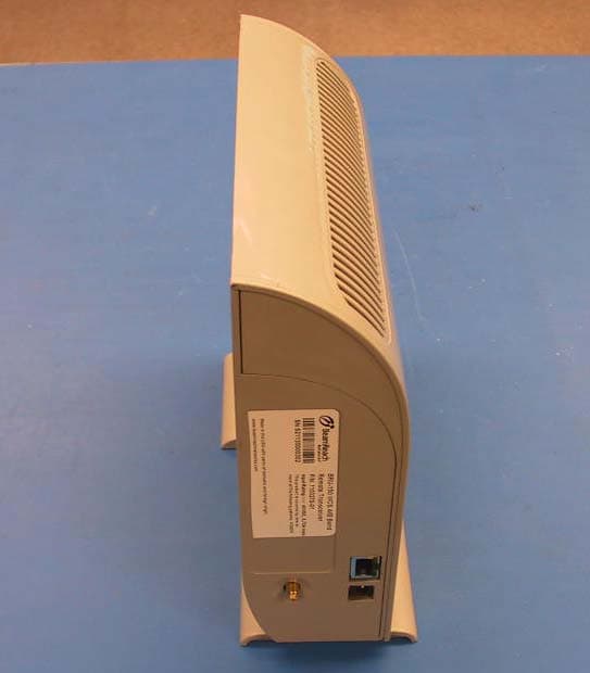
QONBRU150
Nov 20, 2003Wireless Indoor Remote Unit
Equipment Class
TNB - Licensed Non-Broadcast Station Transmitter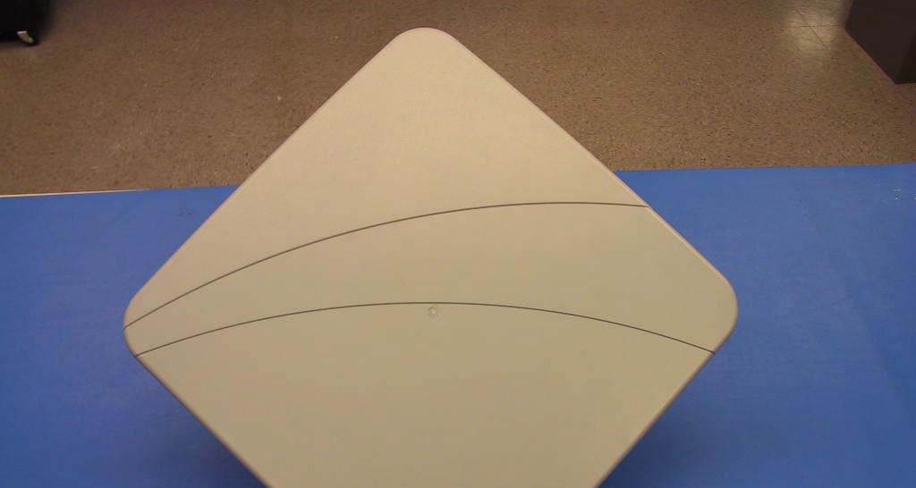
QONBRU100
Nov 20, 2003Wireless Outdoor Remote Unit
Equipment Class
TNB - Licensed Non-Broadcast Station Transmitter