QONBRU150Wireless Indoor Remote Unit
BeamReach Networks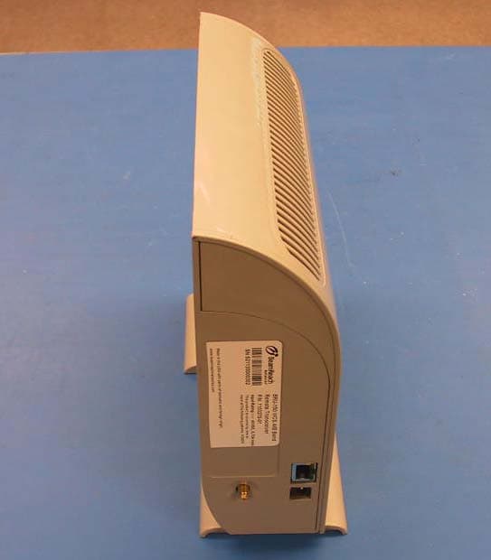
Click to zoom
Application Details
- Equipment Class
- TNB - Licensed Non-Broadcast Station Transmitter
- Date of Grant
- Nov 20, 2003
- Application Purpose
- Original Equipment
- Date of Application
- Nov 20, 2003
- Equipment Note
- Wireless Indoor Remote Unit
- Frequency Range
- 2351.25000000 - 2358.75000000
- Company
- BeamReach Networks
- Country
- United States
Documents & Files
Document Text
Text extracted from the exhibit documents filed with the FCC. Open a document above to read the original.
Users Manual
Installation Quick Guide I n s t a l l a t i o n Q u i c k G u i d e for the f o r t h e BeamPlexB e a m P l e x ™ BRU-150 B R U - 1 5 0 Wireless Broadband SystemW i r e l e s s B r o a d b a n d S y s t e m Antenna, Cable and Parts Bag Your BeamPlex™ BRU-150 Wireless Broadband System comes with the following items. Please verify that you have all these items before proceeding with the installation. ✔ BRU-150 Transceiver ✔ Power supply and cord ✔ Antenna, cable and parts ✔ Ethernet cable ✔ Operation Manual ✔ This Quick Guide Before you begin ... Power Supply and Cord BRU-150 Transceiver A IR LIN K S Y N C S I G N A L S T R E N G T H B RU -150 Ethernet Cable BRU-150 Operation Manual Step 1 - Preparing your computer ... Step 2 - Installing the antenna ... Antenna Antenna Cable Logo "California Amplifier" Your computer must be configured with the following items to accommodate wireless broadband: ✔ An Ethernet (NIC) card. ✔ The installation CD supplied by your service provider (must include a PPPoE client). ✔ A compatible IP address. Ethernet CardInstall the Ethernet card using the instructions supplied by the manufacturer.Insert one end of the Ethernet cable that came with the BRU-150 into the RJ-45 connector in the Ethernet card. Installation CDRun the installation CD according to the directions supplied by your service provider. Assemble the antennaIn the package that contains the antenna you will find a bag with brackets, adhesive dots, and screws.Snap the brackets onto the posts at the top and bottom of the antenna. The brackets are designed to rotate freely on the posts.Affix an adhesive dot to both brackets.Insert the antenna cable into the connector inside the bottom post of the antenna. There is a "California Amplifier" logo near the bottom end of the antenna. Push firmly until you feel the connector snap into place. IP AddressConfigure the IP address in your computer to the following settings: Address 192.168.1.X Where X = any number between 2 and 255 Subnet 255.255.255.0 See the Operation Manual for specific instructions. If you are connecting to a network though a hub or router, see the Operation Manual. The antenna is designed to mount in a window. Select a window that has a view in the direction of the closest base station, based on the base station locations supplied by your service provider.The antenna comes with adhesive dots to stick to the glass. As an option, the antenna can be attached to the window frame with the supplied screws. Antenna Post Bracket Adhesive Dot Attach the antennaClean the window before attaching the antenna to it.Hold the antenna straight up and down. The logo should be at the bottom and facing inward, away from the window.Align the brackets so that the adhesive dots will contact the window, then press the assembly against the glass. For best reception: • Position the antenna high in the window.• Select a window with no obstructions such as trees or buildings close to it. • Avoid a window that has a metal screen.• Avoid being near other sources of emissions, such as computer monitors, televisions, microwave ovens, or wireless telephones. DATA ANTENNA 48V .7A Step 3 - Connecting the cables ... There are three cables for you to connect: • Antenna cable• Power supply cable• Ethernet cable All cables connect to the back panel of the BRU-150 Transceiver. Antenna Cable (10 feet) Power Supply (11 feet) Ethernet Cable After you have connected all the the cables to the BRU-150, plug the power supply into the wall outlet and observe the lights on the front panel as described in Step 4. BRU-150 Transceiver 110 or220 Volts If the supplied Ethernet cable is too short, you can use a cable up to 300 feet long. Connect to Ethernet Card SIGNAL STRENGTH AIR LINK SYNC Step 4 - Linking with a base station ... When power is first applied to the BRU-150, the lights on the front panel of the Transceiver will blink randomly for a few seconds. Then, the SYNC light will turn amber and flash slowly while the Transceiver searches for a signal from a base station. When BRU-150 makes an initial link with a base station, the SYNC light turns green and some or all of the SIGNAL STRENGTH lights turn on. If the SYNC light does not turn green in about 60 seconds, you will have to adjust the antenna. This is explained in the panels on the right of this page. When the BRU-150 has completed linking to a base station, the AIR LINK light will turn green. If you did not link with a base station ...You were left with a SYNC light flashing amber.First, try pointing the antenna in different directions. If you still did not link with a base station ...Then you will have to move the antenna to a different window. First, to remove the antenna from the current window, use a plastic scrapper to wedge between the bracket and the window. Pull gently on the backet. DO NOT pull on the antenna.Next, refer to base station location information supplied by your service provider and select another window in the direction of a base station. Attach the antenna as described in Step 2. The antenna can rotate inside the brackets that are attached to the window.Rotate the antenna about 1/4 of a turn in one direction. Then wait 60 seconds to see if the SYNC light turns green.If the SYNC light stays flashing amber, rotate the antenna 1/4 of a turn in the other direction and wait 60 seconds. You may need to move the Transceiver when you move the antenna. If so, you can safely disconnect and connect any of the cables with power applied. However, you must unplug the power supply (either from the wall outlet or the Transceiver connector) and then reconnect to cycle the power. This causes the BRU-150 to restart the base station search. After the AIR LINK light turns green, proceed to Step 5. Step 5 - Optimizing signal quality ... Congratulations ...You can now connect to your service provider's network. Follow the login instructions that they provided.If this installation process was not successful, see the BRU-150 Oper…
Text truncated - open the document above for the full version.
Users Manual
BeamPlex BRU-100 and BRU-150 Remote Unit Installation and Maintenance Service Utilities 1106333-01 Rev. 3 Nov. 2003 ii Legal Notices This document is published in association with the products of BeamReach Networks Incorporated. Due to ongoing product development and improvements, BeamReach Networks makes no representations or warranties with respect to the accuracy or completeness of this document and reserves the right to make changes without notice. Patents Products and technologies described herein include those covered by one or more U.S. patents owned by BeamReach Networks Incorporated. Copyrights © 2003 BeamReach Networks Incorporated. All rights reserved. No part of this document may be copied, photocopied, reproduced, translated, or reduced to any electronic medium or machine- readable form without prior written consent from BeamReach Networks Incorporated. Printed in the United States of America. Trademarks BeamPlex and Adaptive MultiBeam OFDM are trademarks of BeamReach Networks Incorporated. All other brand names are trademarks of their respective holders. Revision History Document number 1106333-01 This document applies to System Software versions subsequent to that which is listed here, unless the document is reissued due to software feature upgrades. The software release notes will indicate the applicable document revision level. BeamReach Networks 755 North Mathilda Ave. Sunnyvale, CA 94086 408.869.8700 www.BeamReachNetworks.com Revision StatusRevision LevelDateSystem Release Pre-ProductionRev 1April 20031.1 Pre-ProductionRev 2June 20031.1 Pre-ProductionRev 3November 20031.1 1106333-01Pre-Productioniii Revision 3 Table of Contents Chapter 1 – Introduction . . . . . . . . . . . . . . . . . . . . . . . . . . . . . . . . . . . . . . . . . . . . . . . 1 Overview . . . . . . . . . . . . . . . . . . . . . . . . . . . . . . . . . . . . . . . . . . . . . . . . . . . . . . . . . . . . . . . . . . . . . . . 2 Scope and Purpose . . . . . . . . . . . . . . . . . . . . . . . . . . . . . . . . . . . . . . . . . . . . . . . . . . . . . . . . . . . . 2 Important Notices . . . . . . . . . . . . . . . . . . . . . . . . . . . . . . . . . . . . . . . . . . . . . . . . . . . . . . . . . . . . . 3 Remote Unit Models . . . . . . . . . . . . . . . . . . . . . . . . . . . . . . . . . . . . . . . . . . . . . . . . . . . . . . . . . . . 3 Remote Unit Service Utilities . . . . . . . . . . . . . . . . . . . . . . . . . . . . . . . . . . . . . . . . . . . . . . . . . . . . . . . 5 BRU Installation Tool (BRUIT) . . . . . . . . . . . . . . . . . . . . . . . . . . . . . . . . . . . . . . . . . . . . . . . . . .5 BRU Status Monitor . . . . . . . . . . . . . . . . . . . . . . . . . . . . . . . . . . . . . . . . . . . . . . . . . . . . . . . . . . . 5 BRU-150 Transceiver Features . . . . . . . . . . . . . . . . . . . . . . . . . . . . . . . . . . . . . . . . . . . . . . . . . . . . . . 6 Installation Overview . . . . . . . . . . . . . . . . . . . . . . . . . . . . . . . . . . . . . . . . . . . . . . . . . . . . . . . . . . . . . . 8 BRU-150 Self-Install Remote Unit . . . . . . . . . . . . . . . . . . . . . . . . . . . . . . . . . . . . . . . . . . . . . . . .8 BRU-100 Professional Install Remote Unit . . . . . . . . . . . . . . . . . . . . . . . . . . . . . . . . . . . . . . . . . 8 Reference Documents . . . . . . . . . . . . . . . . . . . . . . . . . . . . . . . . . . . . . . . . . . . . . . . . . . . . . . . . . . . . . 9 Chapter 2 – Preparation . . . . . . . . . . . . . . . . . . . . . . . . . . . . . . . . . . . . . . . . . . . . . . 11 Service Computer . . . . . . . . . . . . . . . . . . . . . . . . . . . . . . . . . . . . . . . . . . . . . . . . . . . . . . . . . . . . . . . . 12 Computer . . . . . . . . . . . . . . . . . . . . . . . . . . . . . . . . . . . . . . . . . . . . . . . . . . . . . . . . . . . . . . . . . . . 12 Ethernet Cable . . . . . . . . . . . . . . . . . . . . . . . . . . . . . . . . . . . . . . . . . . . . . . . . . . . . . . . . . . . . . . . 12 IP Address . . . . . . . . . . . . . . . . . . . . . . . . . . . . . . . . . . . . . . . . . . . . . . . . . . . . . . . . . . . . . . . . . . 13 Software . . . . . . . . . . . . . . . . . . . . . . . . . . . . . . . . . . . . . . . . . . . . . . . . . . . . . . . . . . . . . . . . . . . . . . . 13 Service Utilities . . . . . . . . . . . . . . . . . . . . . . . . . . . . . . . . . . . . . . . . . . . . . . . . . . . . . . . . . . . . . . 13 Software Image . . . . . . . . . . . . . . . . . . . . . . . . . . . . . . . . . . . . . . . . . . . . . . . . . . . . . . . . . . . . . . 13 Service Order File . . . . . . . . . . . . . . . . . . . . . . . . . . . . . . . . . . . . . . . . . . . . . . . . . . . . . . . . . . . . 14 BRU-100 . . . . . . . . . . . . . . . . . . . . . . . . . . . . . . . . . . . . . . . . . . . . . . . . . . . . . . . . . . . . . . . 14 BRU-150 . . . . . . . . . . . . . . . . . . . . . . . . . . . . . . . . . . . . . . . . . . . . . . . . . . . . . . . . . . . . . . . 14 Equipment and Material . . . . . . . . . . . . . . . . . . . . . . . . . . . . . . . . . . . . . . . . . . . . . . . . . . . . . . . . . . . 17 Chapter 3 – Installation Tool . . . . . . . . . . . . . . . . . . . . . . . . . . . . . . . . . . . . . . . . . . 19 Preface . . . . . . . . . . . . . . . . . . . . . . . . . . . . . . . . . . . . . . . . . . . . . . . . . . . . . . . . . . . . . . . . . . . . . . . . 20 BRU-150 Pre-Configuration . . . . . . . . . . . . . . . . . . . . . . . . . . . . . . . . . . . . . . . . . . . . . . . . . . . .20 Antenna Location . . . . . . . . . . . . . . . . . . . . . . . . . . . . . . . . . . . . . . . . . . . . . . . . . . . . . . . . . . . . 21 Installation Tool Operation . . . . . . . . . . . . . . . . . . . . . . . . . . . . . . . . . . . . . . . . . . . . . . . . . . . . . . . . 22 Step 1 Physical Installation . . . . . . . . . . . . . . . . . . . . . . . . . . . . . . . . . . . . . . . . . . . . . . . . . . . 22 LAN Con…
Text truncated - open the document above for the full version.
Cover Letter(s)
To: David Chernomordik ES-Mpk Subject: BeamReach FCC ID: QONBRU150 David, Review of this application is complete, and the following points are noted (earlier comments are repeated here for completeness): ADMINISTRATIVE A. Confidentiality request (this has been corrected) 1) Each application should have a separate request letter only referencing the applicable FCC ID. Do not cite two different FCC ID numbers in one letter. 2) The request letter does not reference the relevant FCC Rule parts applicable to confidentiality, namely, 0.457. This should be added. B. FCC Identifier 1) No FCC Identifier appears on the label drawing for FCC ID: QONBRU150. The FCC Identifier must appear on the product. TECHNICAL None. Regards, Roland
External Photos
FCC ID: QONBRU100
ID Label/Location Info
FCC ID: QONBRU100
Internal Photos
FCC ID: QONBRU150 Figure 1. BRU-150, View into Plastic Enclosure with Metalized EMI Shielding. Figure 2. BRU-150, Right Housing Segment with Front Panel LED Board and Cable. Figure 3. BRU-150, Front Panel LED Board and Cable. Figure 4. BRU-150 RF PWA, top view, no shields. Figure 5. BRU-150 RF PWA, Bottom View, No Shields. Figure 6. BRU-150 DC-DC Power Supply PWA Top View. Figure 7. BRU-150 DC-DC Po wer Supply PWA Bottom View. Figure 8. BRU-150 Digital PWA Top View. Figure 9. BRU-150 Digital PWA Bottom View. Figure 10. BRU-Antenna with 4 Foot Cable.
Operational Description
C H A P T E R 5 Remote Unit In This Chapter: Overview Architecture Remote Unit Components Subscriber LAN Architectures This chapter provides descriptions of the BRU-100 and BRU- 150 Remote Unit (RU). Overview BeamPlex remote units operate cost-effectively in non-line-of-sight environments and provide high speed, near-symmetric connections to broadband customers. Two models of the remote unit are available: BRU-100 – Outdoor, service provider installation. Includes the outdoor unit (ODU), power supply, power injector, associated cabling and software. A RIT Interface Box is optional. The ODU typically attaches to an exterior wall or roof. BRU-150 – Indoor, subscriber self-installation. Includes the transceiver (indoor unit), window-mount antenna, power supply, and software. Both models use the same electronics and function in the same manner. The remote unit provides the wireless termination point for the BeamPlex system at the subscriber’s location. It connects to the subscriber's terminal equipment (computer) across a LAN, or directly by Ethernet 10/100 BaseT. The airlink serves as the connection between the subscriber’s computer and the base station. It utilizes the BeamReach-developed Adaptive MultiBeam OFDM technology. Depending on the airlink signal strength, different data rates are possible. See Appendix B "Remote Unit Specifications” for reference. BRU-100 A BRU-100 remote unit consists of the following major components: Outdoor Unit – RF assembly; digital assembly with ASICs and microprocessors; DC/DC power supply; 16-element array antenna with 20° beamwidth and 18 dBi gain Power Adapter – 110/220 VAC input; 48 VDC output for the RF and digital circuitry in the outdoor unit Power Injector – 8-lead Ethernet from computer plus power and return from Power Adapter; 6-lead output to outdoor unit RIT Interface Box (RIB) – Optional device; mounts to outside wall; 10- pin RJ-45 for connecting to outdoor unit RU Installation Tool (RIT) – Software application in handheld PC to facilitate the installation process BRU-150 A BRU-150 remote unit consists of the following major components: Transceiver – This indoor unit has the same electronics as the BRU-100’s outdoor unit, except that it does not have an integrated antenna. Antenna – A window-mount, directional antenna with approximately 90° beamwidth housed in a transparent enclosure. Power supply – Connects to standard 120 VAC and outputs 48 VDC to the transceiver. Future versions of the remote unit are planned to include the following models and added capabilities: BRU-450 – High capacity business model HPNA – Home Phone Network Alliance support (in Version 1.0) VoIP – Voice over IP support BRU-100 Features and Benefits The BRU-100 is a fully integrated remote unit suitable for professional installation in outdoor environments. Using a high gain antenna, the BRU-100 maximizes cell coverage and range in challenging propagation environments. The outdoor unit provides for simple, fast, low cost installations and high operational reliability. Ethernet connectivity makes it compatible with all types of subscriber LAN equipment. Features • Fully integrated outdoor unit • Single drop cable for power and subscriber interface • Non-line-of-sight operation (NLOS) • Sustained throughput up to 1.5 Mbps (downlink) and 1.2 Mbps (uplink) • Multi-level QoS and SLA support • Ethernet user interface • PPP/Bridged Ethernet networking model • Automatic link quality measurements • Remote configuration and management • 2.3 GHz (WCS) band operationand 2.5–2.7 GHz (MMDS/ITFS) Benefits • Reduced installation time and cost – NLOS, below the roof line – One piece outdoor unit, simple cabling • Reduced operational costs – Over the air service management and configuration – Over the air software upgrades • Flexible service offerings – Variable service rates – 64 kbps to 1.5 Mbps downlink, up to 1.2 Mbps uplink – Multi level QoS via DiffServ, service provider defined SLAs – Service transparency using bridged Ethernet model • High quality voice services, file swapping and streaming media • Increased cell coverage in comparison to the BRU-150 • Subscriber equipment compatibility – Standard Ethernet LAN interface – Compatible with standard NICs, hubs, routers, firewalls and 802.11 WLANs BRU-150 Features and Benefits The BRU-150 is a fully integrated remote unit designed for subscriber selfinstallation. The high gain, wide beamwidth antenna minimizes the need for pointing to establish an airlink with a base station. The installation process is automated, requiring minimal user actions. Features • Fully integrated transceiver packaged in an aesthetic housing for indoor use • Simple wiring and automated process for ease of installation • Diagnostic software on subscriber’s computer to assist customer support calls • Non-line-of-sight operation (NLOS) • Sustained throughput up to 1.5 Mbps (downlink) and 1.2 Mbps (uplink) • Ethernet user interface • PPP/Bridged Ethernet networking model • Remote configuration and management • 2.3 GHz (WCS) Benefits • Subscriber self-installation, no truck roll required • Reduced operational costs – Over the air service management and configuration – Over the air software upgrades • Flexible service offerings – Variable service rates – 64 Kbps to 1.5 Mbps downlink, up to 1.2 Mbps uplink – Multi level QoS via DiffServ, service provider defined SLAs – Service transparency using bridged Ethernet model • High quality voice services, file swapping and streaming media • Subscriber equipment compatibility – Standard Ethernet LAN interface – Compatible with standard NICs, hubs, routers, firewalls and 802.11 WLANs Remote Unit Interfaces For both models of the RU there are two basic interfaces: The airlink to the base station. The Ethernet data interface to the Customer Premise Equipment (CPE). All CPE connects to the RU through an Ethernet data interface. Network equipment can be used to connect multiple CPE to the RU. Future versions of the BRU-100 wil…
Text truncated - open the document above for the full version.
RF Exposure Info
Computation of Distance to Center of Radiation of Antenna vs Power into Antenna, Antenna Gain, and Allowed Power Density BEAMREACH NETWORKS MAXIMUM PERMISSIBLE EXPOSURE CALCULATIONS Calculation of mpe distance per product specifications Unit Average Power into Antenna during Tx Interval (dBm) Tx Duty Cycle (dB) Average Power into Antenna, P (dBm) Antenna Gain, G (dBi) Power Density, S (mW/cm^2) Distance to Center of Radiation of Antenna, R (cm) ODU CPE30-3.8926.1118520.24 IDU CPE30-3.8926.1111120.22 Base (5W)37-2.9234.0817545.16 Base (10W)40-2.9237.0817563.78 S = P*G/(4*pi*R^2), far field calculation R = SQRT(P*G/(4*pi*S)) Note: 1. FCC limit for general population/uncontrolled exposure is 1mW/cm^2. 2. FCC limit for occupation/controlled exposure is 5mW/cm^2. Unit Average Power into Antenna during Tx Interval (dBm) Tx Duty Cycle (dB) Average Power into Antenna, P (dBm) Antenna Gain, G (dBi) Power Density, S (mW/cm^2) Distance to Center of Radiation of Antenna, R (cm) ODU CPE28.5-3.8924.6118517.03 IDU CPE27-3.8923.1111114.31 Calculation of mpe distance per product average power measurements
Test Report
EMC Report for BeamReach Networks on the BRU-150 File: 30408642 Page 1 of 75 TEST REPORT Report Number: 30408642 Project Number: 3040864 & 3030973 June 10, 2003 Testing performed on the Wireless Indoor Remote Unit Model: BRU-150 FCC ID: QONBRU150 to FCC Part 27 for BeamReach Networks Test Performed by: Test Authorized by: Intertek Testing Services 1365 Adams Court Menlo Park, CA 94025 BeamReach Networks 755 North Mathilda Avenue Sunnyvale, CA 94086 Prepared by: Date: 6/10/03 Arkadi Kaplan Reviewed by: Date: 7/17/03 David Chernomordik This report is for the exclusive use of Intertek's Client and is provided pursuant to the agreement between Intertek and its Client. Intertek's responsibility and liability are limited to the terms and conditions of the agreement. Intertek assumes no liability to any party, other than to the Client in accordance with the agreement, for any loss, expense or damage occasioned by the use of this report. Only the Client is authorized to copy or distribute this report and then only in its entirety. Any use of the Intertek name or one of its marks for the sale or advertisement of the tested material, product or service must first be approved in writing by Intertek. The observations and test results in this report are relevant only to the sample tested. This report by itself does not imply that the material, product, or service is or has ever been under an Intertek certification program. This report must not be used to claim product endorsement by A2LA, NIST nor any other agency of the U.S. Government. EMC Report for BeamReach Networks on the BRU-150 File: 30408642 Page 2 of 75 TABLE OF CONTENTS 1.0 Summary of Tests ........................................................................................................................ 3 2.0 General Description ..................................................................................................................... 4 2.1 Product Description .......................................................................................................... 4 2.2 Related Submittal(s) Grants .............................................................................................. 5 2.3 Test Facility ...................................................................................................................... 5 3.0 System Test Configuration.......................................................................................................... 5 3.1 Support Equipment ........................................................................................................... 5 3.2 Block Diagram of Test Setup............................................................................................ 6 4.0 RF Power Output, Radiated Power............................................................................................ 8 4.1 Requirements ....................................................................................................................8 4.2 Test Procedure ..................................................................................................................8 4.3 Test Results....................................................................................................................... 8 5.0 Occupied Bandwidth ................................................................................................................... 9 5.1 Test Procedure ..................................................................................................................9 5.2 Test Results....................................................................................................................... 9 6.0 Spurious Emissions at Antenna Terminal ............................................................................... 12 6.1 Requirements .................................................................................................................. 12 6.2 Test Procedure ................................................................................................................ 12 6.3 Test Results..................................................................................................................... 12 7.0 Field Strength of Spurious Radiation ...................................................................................... 13 7.1 Requirements .................................................................................................................. 13 7.2 Test Procedure ................................................................................................................ 13 7.3 Test Result ...................................................................................................................... 14 8.0 AC Line Conducted Emissions ................................................................................................. 16 8.1 Test Procedure ................................................................................................................ 16 8.2 Test Results..................................................................................................................... 17 9.0 Frequency Stability vs Temperature and Voltage .................................................................. 30 9.1 Test Procedure ................................................................................................................ 30 9.2 Test Results..................................................................................................................... 30 10.0 List of Test Equipment .............................................................................................................. 32 11.0 Document History ...................................................................................................................... 33 12.0 Appendix A ................................................................................................................................. 34 13.0 Appendi…
Text truncated - open the document above for the full version.
Test Report
EMC Report for BeamReach Networks on the BRU-150 File: 30408642 Page 34 of 75 12.0 Appendix A Sub band A1 (operating center frequencies: 2306.25 and 2351.25 MHz) Plot Number Description 1.1 Scan 10 MHz – 1 GHz 1.2 Scan 1 GHz – 2.300 GHz 1.3 Scan 2.300 GHz – 2.310 GHz 1.4 Scan 2.315 GHz – 2.320 GHz 1.5 Scan 2.320 GHz – 2.345 GHz 1.6 Scan 2.450 GHz – 2.355 GHz 1.7 Scan 2.360 GHz – 2.370 GHz 1.8 Scan 2.370 GHz – 6.4 GHz 1.9 Scan 6.4 GHz – 24 GHz Sub band A3 (operating center frequencies: 2308.75 and 2353.75 MHz) Plot Number Description 2.1 Scan 10 MHz – 1 GHz 2.2 Scan 1 GHz – 2.300 GHz 2.3 Scan 2.300 GHz – 2.310 GHz 2.4 Scan 2.315 GHz – 2.320 GHz 2.5 Scan 2.320 GHz – 2.345 GHz 2.6 Scan 2.450 GHz – 2.355 GHz 2.7 Scan 2.360 GHz – 2.370 GHz 2.8 Scan 2.370 GHz – 6.4 GHz 2.9 Scan 6.4 GHz – 24 GHz EMC Report for BeamReach Networks on the BRU-150 File: 30408642 Page 35 of 75 Sub band B1 (operating center frequencies: 2311.25 and 2356.25 MHz) Plot Number Description 3.1 Scan 10 MHz – 1 GHz 3.2 Scan 1 GHz – 2.300 GHz 3.3 Scan 2.300 GHz – 2.310 GHz 3.4 Scan 2.315 GHz – 2.320 GHz 3.5 Scan 2.320 GHz – 2.345 GHz 3.6 Scan 2.450 GHz – 2.355 GHz 3.7 Scan 2.360 GHz – 2.370 GHz 3.8 Scan 2.370 GHz – 6.4 GHz 3.9 Scan 6.4 GHz – 24 GHz Sub band B3 (operating center frequencies: 2313.75 and 2358.75 MHz) Plot Number Description 3.1 Scan 10 MHz – 1 GHz 3.2 Scan 1 GHz – 2.300 GHz 3.3 Scan 2.300 GHz – 2.310 GHz 3.4 Scan 2.315 GHz – 2.320 GHz 3.5 Scan 2.320 GHz – 2.345 GHz 3.6 Scan 2.450 GHz – 2.355 GHz 3.7 Scan 2.360 GHz – 2.370 GHz 3.8 Scan 2.370 GHz – 6.4 GHz 3.9 Scan 6.4 GHz – 24 GHz EMC Report for BeamReach Networks on the BRU-150 File: 30408642 Page 36 of 75 Plot 1.1 EMC Report for BeamReach Networks on the BRU-150 File: 30408642 Page 37 of 75 Plot 1.2 EMC Report for BeamReach Networks on the BRU-150 File: 30408642 Page 38 of 75 Plot 1.3 EMC Report for BeamReach Networks on the BRU-150 File: 30408642 Page 39 of 75 Plot 1.4 EMC Report for BeamReach Networks on the BRU-150 File: 30408642 Page 40 of 75 Plot 1.5 EMC Report for BeamReach Networks on the BRU-150 File: 30408642 Page 41 of 75 Plot 1.6 EMC Report for BeamReach Networks on the BRU-150 File: 30408642 Page 42 of 75 Plot 1.7 EMC Report for BeamReach Networks on the BRU-150 File: 30408642 Page 43 of 75 Plot 1.8 EMC Report for BeamReach Networks on the BRU-150 File: 30408642 Page 44 of 75 Plot 1.9 EMC Report for BeamReach Networks on the BRU-150 File: 30408642 Page 45 of 75 Plot 2.1 EMC Report for BeamReach Networks on the BRU-150 File: 30408642 Page 46 of 75 Plot 2.2 EMC Report for BeamReach Networks on the BRU-150 File: 30408642 Page 47 of 75 Plot 2.3 EMC Report for BeamReach Networks on the BRU-150 File: 30408642 Page 48 of 75 Plot 2.4 EMC Report for BeamReach Networks on the BRU-150 File: 30408642 Page 49 of 75 Plot 2.5 EMC Report for BeamReach Networks on the BRU-150 File: 30408642 Page 50 of 75 Plot 2.6 EMC Report for BeamReach Networks on the BRU-150 File: 30408642 Page 51 of 75 Plot 2.7 EMC Report for BeamReach Networks on the BRU-150 File: 30408642 Page 52 of 75 Plot 2.8 EMC Report for BeamReach Networks on the BRU-150 File: 30408642 Page 53 of 75 Plot 2.9 EMC Report for BeamReach Networks on the BRU-150 File: 30408642 Page 54 of 75 Plot 3.1 EMC Report for BeamReach Networks on the BRU-150 File: 30408642 Page 55 of 75 Plot 3.2 EMC Report for BeamReach Networks on the BRU-150 File: 30408642 Page 56 of 75 Plot 3.3 EMC Report for BeamReach Networks on the BRU-150 File: 30408642 Page 57 of 75 Plot 3.4 EMC Report for BeamReach Networks on the BRU-150 File: 30408642 Page 58 of 7…
Text truncated - open the document above for the full version.
Contact Information
Applicant
Anthony Tokuno(Director, Hardware Engineering)
Technical Contact
Intertek Testing ServicesDavid Chernomordik
[email protected]650 463 2900
1365 Adams Court · Menlo Park, California · United States
Non-Technical Contact
Intertek Testing ServicesDavid Chernomordik
[email protected]650 463 2900
Test Firm
Intertek Testing Services NA Inc.John Quigley
Technical Specifications
| # | Rule Parts | Frequency Range | Power Output | Emission | Tolerance |
|---|---|---|---|---|---|
| 2 | 27 | 2.35 GHz - 2.36 GHz | 7 W | 2M50D7D | 0.1 Hz |
Other Applications from BeamReach Networks
QONBRN5000
Nov 22, 2003BeamPlex Base Station Indoor Unit
Equipment Class
TNB - Licensed Non-Broadcast Station Transmitter
QONBRU100
Nov 20, 2003Wireless Outdoor Remote Unit
Equipment Class
TNB - Licensed Non-Broadcast Station Transmitter