QOQ-BGM220SShort Range Device
Silicon Laboratories Finland Oy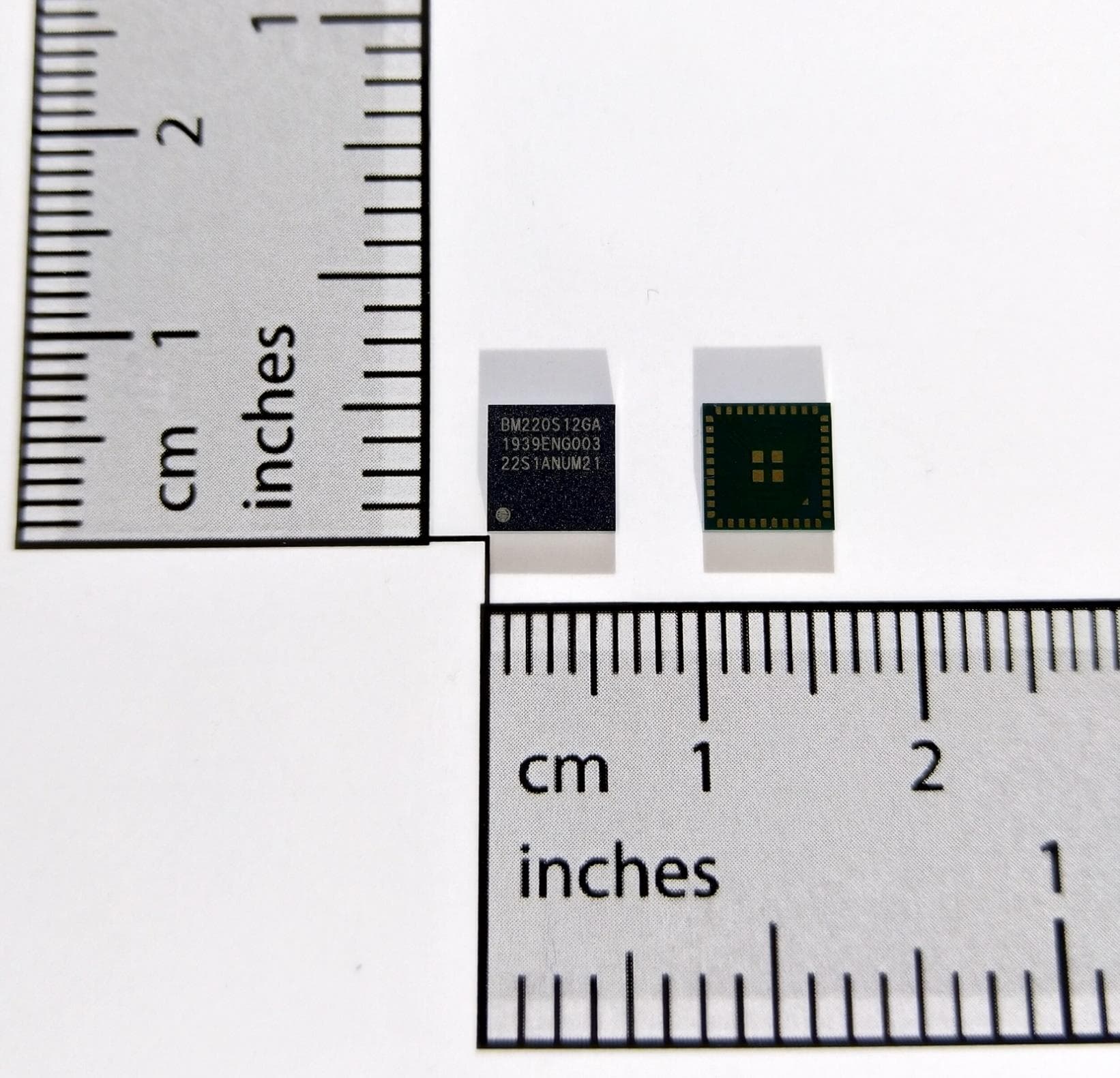
Click to zoom
Application Details
- Equipment Class
- DTS - Digital Transmission System
- Date of Grant
- Aug 04, 2020
- Application Purpose
- Original Equipment
- Date of Application
- Jul 08, 2020
- Equipment Note
- Short Range Device
- Frequency Range
- 2401.00000000 - 2481.00000000
- Country
- Finland
Documents & Files
Document Text
Text extracted from the exhibit documents filed with the FCC. Open a document above to read the original.
Users Manual
BGM220S Wireless Gecko Bluetooth Module Data Sheet The BGM220S is a module designed and built to meet the per- formance, security, and reliability requirements of battery-powered IoT products running on Bluetooth networks. Based on the EFR32BG22 SoC, the BGM220S enables Bluetooth ® Low Energy connec- tivity while delivering best-in-class RF range and performance, future-proof capability for feature and OTA firmware updates, enhanced security features, and low energy con- sumption. BGM220S modules are a full solution that comes with fully-upgradeable, robust software stacks, world-wide regulatory certifications, advanced development and debugging tools, and support that will minimize and simplify the engineering and development of your end-products helping to accelerate their time-to-market. The BGM220S is intended for a broad range of applications, including: • Asset Tags and Beacons • Portable Medical • Sports, Fitness, and Wellness devices • Connected Home • Industrial and Building Automation • Bluetooth mesh Low Power Nodes KEY FEATURES • Bluetooth 5.2 • Built-in antenna or RF pin • Up to 0 dBm TX power • -98.6 dBm BLE RX sensitivity at 1 Mbps • 32-bit ARM Cortex-M33 core at up to 38.4 MHz • 352/32 kB of Flash/RAM memory • Optimal selection of MCU peripherals • 25 GPIO pins • 6 mm × 6 mm × 1.1 mm Lowest power mode with peripheral operational: EM4—Shutoff EM3—StopEM2—Deep SleepEM1—SleepEM0—Active Timers and Triggers 32-bit bus Peripheral Reflex System Serial Interfaces I/O Ports Analog I/F USART EUART External Interrupts General Purpose I/O Pin Reset Pin Wakeup ADC Energy Management Brown-Out Detector Voltage Regulator Power-On Reset SecurityClock Management HF Crystal Oscillator LF Crystal Oscillator Precision LF RC Oscillator HF RC Oscillator Crypto Acceleration Ultra LF RC Oscillator Core / Memory ARM Cortex TM M33 processor with DSP extensions, FPU and TrustZone ETMDebug InterfaceRAM Memory LDMA Controller Flash Program Memory Real Time Capture Counter Timer/ Counter Low Energy Timer Watchdog Timer Protocol Timer True Random Number Generator Fast Startup RC Oscillator Back-Up Real Time Counter I 2 C PDM DC-DC Converter Temperature Sensor Radio Subsystem RFSENSE w/ OOK Detect RX/TX Frontend with Integrated PA Frequency Synthesizer ARM Cortex TM M0+ Radio Controller CRC BUFC RAM FRC DEMOD AGC IFADC MOD Crystals Antenna Discrete Antenna Matching 38.4 MHz silabs.com | Building a more connected world.Preliminary Rev. 0.6 This information applies to a product under development. Its characteristics and specifications are subject to change without notice. 1. Feature List •Supported Protocols • Bluetooth Low Energy (Bluetooth 5.2) •Wireless System-on-Chip • 2.4 GHz radio • TX power up to 0 dBm • High-performance 32-bit ARM Cortex-M33 ® with DSP in- struction and floating-point unit for efficient signal process- ing • 352 kB flash program memory • 32 kB RAM data memory • Embedded Trace Macrocell (ETM) for advanced debugging •High Receiver Performance • -98.6 dBm sensitivity (0.1% BER) at 1 Mbps GFSK • -95.8 dBm sensitivity (0.1% BER) at 2 Mbps GFSK •Low-Energy Consumption • 4.0 mA RX current at 1 Mbps GFSK • 4.6 mA TX current at 0 dBm output power • 26 μA/MHz in Active Mode (EM0) • 1.40 μA EM2 DeepSleep current (RTCC running from LFXO, Full RAM retention) • Regulatory Certifications 1 • FCC • CE • IC/ISEDC • MIC/TELEC • KCC •Wide Operating Range • 1.8 to 3.8 V • -40 to +85 °C •Dimensions • 6 mm × 6 mm × 1.1 mm •Security Features • Secure Boot with Root of Trust and Secure Loader (RTSL) • Hardware Cryptographic Acceleration for AES128/256, SHA-1, SHA-2 (up to 256-bit), ECC (up to 256-bit), ECDSA, and ECDH • True Random Number Generator (TRNG) compliant with NIST SP800-90 and AIS-31 • ARM ® TrustZone ® • Secure Debug with lock/unlock •Wide Selection of MCU Peripherals • 12-bit 1 Msps SAR Analog to Digital Converter (ADC) • 25 General Purpose I/O pins with output state retention and asynchronous interrupts • 8 Channel DMA Controller • 12 Channel Peripheral Reflex System (PRS) • 4 × 16-bit Timer/Counter with 3 Compare/Capture/PWM channels • 1 × 32-bit Timer/Counter with 3 Compare/Capture/PWM channels • 32-bit Real Time Counter • 24-bit Low Energy Timer for waveform generation • 1 × Watchdog Timer • 2 × Universal Synchronous/Asynchronous Receiver/Trans- mitter (UART/SPI/SmartCard (ISO 7816)/IrDA/I 2 S) • 1 × Enhanced Universal Asynchronous Receiver/Transmit- ter (EUART) • 2 × I 2 C interface with SMBus support • Digital microphone interface (PDM) • RFSENSE with selective OOK mode 1.Available at the BGM220S Full-Production release. BGM220S Wireless Gecko Bluetooth Module Data Sheet Feature List silabs.com | Building a more connected world.Preliminary Rev. 0.6 | 2 2. Ordering Information Table 2.1. Ordering Information Ordering CodeProtocol Stack TX Power RatingAntennaRF Shield Flash (kB) RAM (kB)GPIOTemp Range BGM220SC12WGA2Bluetooth 5.20 dBmBuilt-inNo3523225-40 to 85 °C Note: 1.End-product manufacturers must verify that the module is configured to meet regulatory limits for each region in accordance with the formal certification test reports. 2.Devices are pre-programmed with BGAPI UART DFU bootloader. 3.Throughout this document, the devices in the table above may be referred to by their product family name (e.g. BGM220S), by model name (BGM220S12A), or by full ordering code. BGM220S Wireless Gecko Bluetooth Module Data Sheet Ordering Information silabs.com | Building a more connected world.Preliminary Rev. 0.6 | 3 Table of Contents 1. Feature List................................2 2. Ordering Information............................3 3. System Overview..............................6 3.1 Introduction...............................6 3.2 EFR32BG22 SoC.............................7 3.3 Antenna................................7 3.4 Power Supply..............................7 4. Electrical Characteristics...........................8 4.1 Absolute Maximum Ratings..........................8 4.2 General Oper…
Text truncated - open the document above for the full version.
Cover Letter(s)
Silicon Laboratories Finland Oy Alberga Business Park Bertel Jungin aukio 3 FI-02600 Espoo, Finland Phone: +358 9 435 5060 www.silabs.com Cover Letter for Confidentiality Federal Communications Commission (Authorization and Evaluation Division) 7435 Oakland Mills Road, Columbia, MD 21046 Attn: To Whom it May Concern / Application Examiner / Review Engineer / Officer in Charge Re: Permanent Confidentiality Request for FCC ID: QOQ-BGM220S Dear Madam or Sir, We, Silicon Laboratories Finland Oy, a corporation validly organized and existing under the laws of Finland, having its principal place of business at Alberga Business Park, Bertel Jungin aukio 3, 02600 Espoo, Finland, pursuant to Sections 0.457 and 0.459 of the Commission’s Rules, hereby request the permanent confidential treatment of information as outlined below: Schematics, Block Diagram, Bill of Material and Operational Description The above design material relates to the FCC application for equipment authorization in connection with our Bluetooth Low Energy wireless radio module with model names of BGM220S12A, having FCC ID: QOQ-BGM220S. The above design material contains trade secrets and proprietary information not customarily released to the public. The public disclosure of these matters might be harmful to our business and provide unjustified benefits to our competitors. We understand that pursuant to Rule 0.457, disclosure of the application and all other accompanying documentation shall not be made before the date of the related Grant release. Should there be any query regarding this authorization, please do not hesitate to contact the undersigned. Thank you for your attention to this matter. Place and date of issue (of this letter): Espoo, April 09, 2020 Senior Contact: Pasi Rahikkala Job Title: Staff Hardware Engineer, IoT Modules Email: [email protected]
Cover Letter(s)
Silicon Laboratories Finland Oy Alberga Business Park Bertel Jungin aukio 3 FI-02600 Espoo, Finland Phone: +358 9 435 5060 www.silabs.com Modular Request Letter Attn: To Whom it May Concern / Application Examiner / Review Engineer / Officer in Charge Re: Request for FCC modular approval, Model: BGM220S12A, FCC ID: QOQ-BGM220S Dear Madam or Sir, We, Silicon Laboratories Finland Oy, a corporation validly organized and existing under the laws of Finland, having its principal place of business at Alberga Business Park, Bertel Jungin aukio 3, 02600 Espoo, Finland, hereby request a Limited Single-modular approval for the radio equipment referenced above. The radio transmitter device meets most, but not all, the requirements for the Full Single-modular approval as indicated below, as outlined in the FCC KDB 996369 D01 Module Equip Auth Guide v02 1] The radio portion of the module is not contained in its own RF shielding. 2] The device has buffered modulation/data inputs to ensure that the device complies with Part 15 requirements with any type of input signal. 3] The device has its own power supply regulation to ensure compliance with Part 15 requirements regardless of the quality or level of external DC supplying the module from the host unit. 4] The device has a permanently attached antenna, or contains a unique antenna connector, and is marketed to operate only with specific antenna(s), per Sections 15.203, 15.204(b), 15.204(c), 15.212(a), 2.929(b). 5] The device has demonstrated compliance in a stand-alone configuration. 6] The device will not be labeled with a permanently affixed FCC ID label due to the small size; the ID is printed in the packaging label, and the integration manual mentions the ID and the need by the integrator to refer to the ID in the end-product labelling. 7] The device does comply with any and all specific FCC rules applicable to the transmitter, including the provision of all the instructions and conditions for maintaining compliance, as detailed in the integration instructions by the grantee. 8] The device does comply with any and all applicable RF exposure requirements. Should there be any query regarding this request, please do not hesitate to contact the undersigned. Thank you for your attention to this matter. Place and date of issue (of this letter): Espoo, April 30, 2020 Senior Contact: Pasi Rahikkala Job Title: Staff Hardware Engineer, IoT Wireless Modules Email: [email protected]
External Photos
Silicon Laboratories Finland Oy Alberga Business Park, Bertel Jungin aukio 3 FI-02600 Espoo, Finland Phone: +358 9 435 5060 Page 1 of 1 www.silabs.com Photo(s) of the BLE wireless radio module with model name: BGM220S12A Figure 1: Top/Front and Bottom/Rear External View of BGM220S12A
ID Label/Location Info
Silicon Laboratories Finland Oy Alberga Business Park, Bertel Jungin aukio 3 FI-02600 Espoo, Finland Phone: +358 9 435 5060 Page 1 of 2 www.silabs.com Top Markings of the BLE wireless radio module with model name: BGM220S12A Figure 1: Label / Top Markings of BGM220S12A Table 2: Label / Top Markings specification of BGM220S12A for contract manufacturer Silicon Laboratories Finland Oy Alberga Business Park, Bertel Jungin aukio 3 FI-02600 Espoo, Finland Phone: +358 9 435 5060 Page 2 of 2 www.silabs.com Table 2: Label / Top Markings definition of BGM220S12A from datasheet Packaging Label of the BLE wireless radio module with model name: BGM220S12A Figure 2: Packaging Label of BGM220S12A, dedicated to carry information related to regulatory certifications Notes: - Table 2 is taken from chapter 8.3 of datasheet, and is reported here to further clarify the exact content of the top markings, in particular the model name in first row and the key to orderable part number in second row. -The label in figure 2 is a companion to the main packaging label carrying among others the model name / orderable part number and the Silicon Labs brand.
Internal Photos
Silicon Laboratories Finland Oy Alberga Business Park, Bertel Jungin aukio 3 FI-02600 Espoo, Finland Phone: +358 9 435 5060 Page 1 of 1 www.silabs.com Photo(s) of the BLE wireless radio module with model name: BGM220S12A Figure 1: Top/Front and Bottom/Rear External View of BGM220S12A
RF Exposure Info
TÜV SÜD, Octagon House, Concorde Way, Segensworth North, Fareham, Hampshire, United Kingdom, PO15 5RL Tel: +44 (0) 1489 558100 Website: www.tuv-sud.co.uk COMMERCIAL-IN-CONFIDENCE SAR EXCLUSION DOCUMENT Approved by Date 09 April 2020 Jon Kenny Authorised Signatory ©2020 Not to be reproduced, except in its entirety, without the permission of TÜV SÜD Page 1 of 4 Document 75947809-05 Issue 01 2.4 GHz BT Transmitter: Product standard: EN 50663:2017 Generic standard for assessment of low power electronic and electrical equipment related to human exposure restrictions for electromagnetic fields (10 MHz - 300 GHz) Basic standard: EN 62479:2010 Assessment of the compliance of low power electronic and electrical equipment with the basic restrictions related to human exposure to electromagnetic fields (10 MHz to 300 GHz) EN 62479 Section 4.1 Route B and 4.2 Low-power exclusion level P max EN 62479 Section 4.1 states: If the electrical power used by or radiated by the equipment is sufficiently low, the electromagnetic fields emitted will be incapable of producing exposures that exceed the basic restrictions. Four routes A, B, C or D can be used to demonstrate compliance. The route selected is B; B The input power level to electrical or electronic components that are capable of radiating electromagnetic energy in the relevant frequency range is so low that the available antenna power and/or the average total radiated power cannot exceed the low-power exclusion level defined below. The applicable low power exclusion level P max from EN 62479 Table A.1 is 20 mW corresponding to; • ICNIRP (guideline in accordance with Council Recommendation 1999/519/EC), • General Public (exposure tier) • Head and trunk (region of body) Low Power Exclusion Result (Integral Antenna): Frequency (MHz) Power Output mW Antenna Gain Ratio Duty Cycle % Maximum Power (EIRP) * (mW) Separation Distance mm P max Exemption Limit ** (mW) SAR Test Exclusion (Yes/No) 2480 0.89 1.41 98 1.23 0 20 Yes 2402 0.89 1.41 98 1.23 0 20 Yes TÜV SÜD, Octagon House, Concorde Way, Segensworth North, Fareham, Hampshire, United Kingdom, PO15 5RL Tel: +44 (0) 1489 558100 Website: www.tuv-sud.co.uk COMMERCIAL-IN-CONFIDENCE SAR EXCLUSION DOCUMENT Approved by Date 09 April 2020 Jon Kenny Authorised Signatory ©2020 Not to be reproduced, except in its entirety, without the permission of TÜV SÜD Page 2 of 4 Low Power Exclusion Result (External Antenna): Frequency (MHz) Power Output mW Antenna Gain Ratio Duty Cycle % Maximum Power (EIRP) * (mW) Separation Distance mm P max Exemption Limit ** (mW) SAR Test Exclusion (Yes/No) 2480 0.89 2.09 98 1.82 0 20 Yes 2402 0.89 2.09 98 1.82 0 20 Yes * Maximum declared output power (EIRP) of the device including tolerance. ** Select power from EN 62479 Table A.1 for the applicable exposure. The Low Power exclusion threshold has been evaluated using the method described above from information supplied by the manufacturer. Based on the evaluation above, the EUT is categorically excluded from SAR/RF exposure testing. Note: the maximum radiated power output EIRP shown in the low power exclusion result is given by: Integral Antenna P EIRP = P o x G i x Duty Factor P EIRP = 0.89 mW x 1.41 x 0.98 = 1.23 mW Where: P o = 10^(-0.5 dBm/10) = 0.89 mW G i = 10^(1.5 dBi/10) = 1.41 Duty factor = 98 %/100 = 0.98 External Antenna P EIRP = P o x G i x Duty Factor P EIRP = 0.89 mW x 2.09 x 0.98 = 1.82 mW Where: P o = 10^(-0.5 dBm/10) = 0.89 mW G i = 10^(3.2 dBi/10) = 2.09 Duty factor = 98 %/100 = 0.98 ©2020 Not to be reproduced, except in its entirety, without the permission of TÜV SÜD Page 3 of 4 Document Number: 75947809-05 | Issue: 01 COMMERCIAL-IN-CONFIDENCE Manufacturer’s Declaration of Product information (extract): ©2020 Not to be reproduced, except in its entirety, without the permission of TÜV SÜD Page 4 of 4 Document Number: 75947809-05 | Issue: 01 COMMERCIAL-IN-CONFIDENCE
RF Exposure Info
TÜV SÜD, Octagon House, Concorde Way, Segensworth North, Fareham, Hampshire, United Kingdom, PO15 5RL Tel: +44 (0) 1489 558100 Website: www.tuv-sud.co.uk COMMERCIAL-IN-CONFIDENCE SAR EXCLUSION DOCUMENT (PORTABLE) Approved by Date 09 April 2020 Jon Kenny Authorised Signatory ©2020 Not to be reproduced, except in its entirety, without the permission of TÜV SÜD Page 1 of 3 Document 75947809-06 Issue 01 FCC Standalone SAR Test Exclusion Considerations (KDB 447498 D01) Section 4.3.1 a) 100 MHz – 6 GHz – Separation Distance ≤50 mm The 1g SAR Test exclusion thresholds for 100 MHz to 6 GHz test separation distances ≤ 50 mm are determined by: [(max power of channel, including tune-up tolerance, mW) / (min. test separation distance, mm)] [√f (GHz)] ≤ 3.0 for 1g SAR and ≤ 7.5 for 10g extremity SAR. • f (GHz) is the RF channel transmit frequency in GHz. • Power and distance are rounded to the nearest mW and mm before calculation. • The result is rounded to one decimal place for comparison • When the minimum test separation distance is < 5 mm, a distance of 5 mm is applied. (Exclusion is also valid at distances less than 5 mm.) SAR Exclusion Result: Frequency (GHz) Power Output mW Duty Cycle % Maximum Power (Tune up Value) * (mW) Test Separation Distance (mm) SAR Test Exclusion Threshold Limit** SAR Test Exclusion (Yes/No) 2.480 1 98 0.98 5 0.3 3.0 Yes 2.402 1 98 0.98 5 0.3 3.0 Yes * Maximum power including tolerance of the time averaged declared conducted output power of the device. ** Select ≤ 3.0 for 1g SAR and ≤ 7.5 for 10g extremity SAR. The SAR exclusion threshold has been evaluated using the formula described above from information supplied by the manufacturer below. Based on the calculation above, the EUT is categorically excluded from SAR testing in stand alone operation. However SAR evaluation may be required for the end product incorporating the module, where simultaneous transmission and co located antennas are used. ©2020 Not to be reproduced, except in its entirety, without the permission of TÜV SÜD Page 2 of 3 Document Number: 75947809-06 | Issue: 01 COMMERCIAL-IN-CONFIDENCE Manufacturer’s Declaration of Product Information: ©2020 Not to be reproduced, except in its entirety, without the permission of TÜV SÜD Page 3 of 3 Document Number: 75947809-06 | Issue: 01 COMMERCIAL-IN-CONFIDENCE
RF Exposure Info
TÜV SÜD, Octagon House, Concorde Way, Segensworth North, Fareham, Hampshire, United Kingdom, PO15 5RL Tel: +44 (0) 1489 558100 Website: www.tuv-sud.co.uk COMMERCIAL-IN-CONFIDENCE SAR EXCLUSION DOCUMENT Approved by Date 09 April 2020 Jon Kenny Authorised Signatory ©2020 Not to be reproduced, except in its entirety, without the permission of TÜV SÜD Page 1 of 4 Document 75947809-09 Issue 01 2402-2480 MHz BT Transmitters: ISED RSS-102 Issue 5: Exemption Limits for Routine Evaluation – SAR Evaluation (RSS-102 Section 2.5.1) Up to 6 GHz – Separation Distance ≤200 mm The SAR evaluation exemption is determined by comparison of the output power level (adjusted for tune-up tolerance) for the specified comparison distance to the limit given in RSS-102 Table 1. SAR Exclusion Result – Portable And Mobile (External Antenna): Frequency (MHz) Power Output mW Antenna Gain Ratio Duty Cycle % Maximum Power (Tune up value) * (mW) Test Separation Distance (mm) ** Exemption Limit *** (mW) SAR Test Exclusion (Yes/No) 2480 0.89 2.09 98 1.823 0 4 Yes 2402 0.89 2.09 98 1.823 0 4 Yes 2480 0.89 2.09 98 1.823 200 308 Yes 2402 0.89 2.09 98 1.823 200 320 Yes SAR Exclusion Result - Portable And Mobile (Integral Antenna): Frequency (MHz) Power Output mW Antenna Gain Ratio Duty Cycle % Maximum Power (Tune up value) * (mW) Test Separation Distance (mm) ** Exemption Limit *** (mW) SAR Test Exclusion (Yes/No) 2480 0.89 1.41 98 1.230 0 4 Yes 2402 0.89 1.41 98 1.230 0 4 Yes 2480 0.89 1.41 98 1.230 200 308 Yes 2402 0.89 1.41 98 1.230 200 320 Yes * Maximum power tune up value including tolerance and is the higher of the maximum conducted or equivalent isotropically radiated power (EIRP) source-based, time-averaged output power of the device derived from FCC Determination of the EIRP given in the measurement and calculations overleaf. **Test separation distance refers to the minimum test separation distance based on the smallest distance between the antenna and radiating structures or the outer surface of the device, according to TÜV SÜD, Octagon House, Concorde Way, Segensworth North, Fareham, Hampshire, United Kingdom, PO15 5RL Tel: +44 (0) 1489 558100 Website: www.tuv-sud.co.uk COMMERCIAL-IN-CONFIDENCE SAR EXCLUSION DOCUMENT Approved by Date 09 April 2020 Jon Kenny Authorised Signatory ©2020 Not to be reproduced, except in its entirety, without the permission of TÜV SÜD Page 2 of 4 the most conservative exposure condition for the applicable module or host platform test procedure requirements, to any part of the body or extremity of a user or bystander. *** Select power from RSS-102 Table 1 for the applicable frequency and separation distance. For controlled use devices where the 8 W/kg for 1 gram of tissue applies, the exemption limits for routine evaluation in Table 1 are multiplied by a factor of 5. For limb-worn devices where the 10 gram value applies, the exemption limits for routine evaluation in Table 1 are multiplied by a factor of 2.5. If the operating frequency of the device is between two frequencies located in Table 1, linear interpolation shall be applied for the applicable separation distance. The SAR exclusion threshold has been evaluated using the method described above from information supplied by the manufacturer. Based on the evaluation above, the EUT is categorically excluded from SAR testing. However SAR evaluation may be required for the end product incorporating the module, where simultaneous transmission and co located antennas are used. ©2020 Not to be reproduced, except in its entirety, without the permission of TÜV SÜD Page 3 of 4 Document Number: 75947809-09 | Issue: 01 COMMERCIAL-IN-CONFIDENCE Manufacturer’s Declaration of Product information : ©2020 Not to be reproduced, except in its entirety, without the permission of TÜV SÜD Page 4 of 4 Document Number: 75947809-09 | Issue: 01 COMMERCIAL-IN-CONFIDENCE
RF Exposure Info
TÜV SÜD, Octagon House, Concorde Way, Segensworth North, Fareham, Hampshire, United Kingdom, PO15 5RL Tel: +44 (0) 1489 558100 Website: www.tuv-sud.co.uk COMMERCIAL-IN-CONFIDENCE SAR EXCLUSION DOCUMENT (MOBILE) Approved by Date 09 April 2020 Jon Kenny Authorised Signatory ©2020 Not to be reproduced, except in its entirety, without the permission of TÜV SÜD Page 1 of 4 Document 75947809-10 Issue 01 2.4 GHz BT Transmitter: FCC Standalone SAR Test Exclusion Considerations (KDB 447498 D01) Section 4.3.1 b) 100 MHz – 6 GHz – Separation Distance >50 mm The SAR Test exclusion thresholds for 1500 MHz to 6 GHz test separation distances >50 mm are determined by: Step a) Threshold result from Formula in Section 4.3.1 a); The Step a) formula has to be re-arranged to give power allowed at numeric threshold at 50 mm test separation distance as required by Step b): Power Allowed at Numeric Threshold = {(Numeric Threshold / √ f (GHz) ) x 50 mm Separation Distance} mW • Numeric threshold = 3 for Head/Body or 7.5 for Extremities • f (GHz) is the RF channel transmit frequency in GHz. • Power and distance are rounded to the nearest mW and mm before calculation. • The result is rounded to one decimal place for comparison Step b) 2) 1500MHz to 6GHz Power threshold = {[Power allowed at numeric threshold for 50 mm {Formula Step A})] + [(test separation distance – 50 mm)·10]} mW • Power and distance are rounded to the nearest mW and mm before calculation. • The result is rounded to one decimal place for comparison ©2020 Not to be reproduced, except in its entirety, without the permission of TÜV SÜD Page 2 of 4 Document Number: 75947809-10 | Issue: 01 COMMERCIAL-IN-CONFIDENCE SAR Exclusion Result: Frequency (MHz) Power Output mW Duty Cycle % Maximum Power (Tune up Value) * (mW) Test Separation Distance (mm) SAR Exclusion Power Threshold (mW) SAR Test Exclusion (Yes/No) 2402 1 98 0.98 200 1595.3 Yes 2480 1 98 0.98 200 1595.3 Yes * Maximum power including tolerance of the time averaged declared conducted output power of the device. The SAR exclusion threshold has been evaluated using the formula described above from information supplied by the manufacturer below. Based on the calculation above, the EUT is categorically excluded from SAR testing in stand alone operation. However SAR evaluation may be required for the end product incorporating the module, where simultaneous transmission and co located antennas are used ©2020 Not to be reproduced, except in its entirety, without the permission of TÜV SÜD Page 3 of 4 Document Number: 75947809-10 | Issue: 01 COMMERCIAL-IN-CONFIDENCE Manufacturer’s Declaration of Product information: ©2020 Not to be reproduced, except in its entirety, without the permission of TÜV SÜD Page 4 of 4 Document Number: 75947809-10 | Issue: 01 COMMERCIAL-IN-CONFIDENCE
Test Report
TÜV SÜD is a trading name of TUV SUD Ltd Registered in Scotland at East Kilbride, Glasgow G75 0QF, United Kingdom Registered number: SC215164 TUV SUD Ltd is a TÜV SÜD Group Company Phone: +44 (0) 1489 558100 Fax: +44 (0) 1489 558101 www.tuv-sud.co.uk TÜV SÜD Octagon House Concorde Way Fareham Hampshire PO15 5RL United Kingdom TÜV SÜD SIGNATURE NAME JOB TITLE RESPONSIBLE FOR ISSUE DATE Steve Marshall Senior Engineer Authorised Signatory 09 April 2020 Signatures in this approval box have checked this document in line with the requirements of TÜV SÜD document control rules. ENGINEERING STATEMENT The measurements shown in this report were made in accordance with the procedures described on test pages. All reported testing was carried out on a sample equipment to demonstrate limited compliance with FCC 47 CFR Part 15C, ISED RSS-247 and ISED RSS-GEN. The sample tested was found to comply with the requirements defined in the applied rules. RESPONSIBLE FOR NAME DATE SIGNATURE Testing Mehadi Choudhury 09 April 2020 Testing Jaiyanth Balendrarajah 09 April 2020 Testing Mohammad Malik 09 April 2020 Testing Ahmad Javid 09 April 2020 Testing Faisal Malyar 09 April 2020 FCC Accreditation 90987 Octagon House, Fareham Test Laboratory ISED Accreditation 12669A Octagon House, Fareham Test Laboratory EXECUTIVE SUMMARY A sample of this product was tested and found to be compliant with FCC 47 CFR Part 15C: 2019, ISED RSS-247: Issue 2 (02- 2017) and ISED RSS-GEN: Issue 5 (04-2018) + A1 (03-2019) for the tests detailed in section 1.3. FCC and ISED Test Report Silicon Laboratories Finland Oy Radio Module, Model: BGM220S12A In accordance with FCC 47 CFR Part 15C, ISED RSS-247 and ISED RSS-GEN Prepared for: Silicon Laboratories Finland Oy Bertel Jungin Aukio 3 Alberga Business Park Espoo 02600 FINLAND FCC ID: QOQ-BGM220S IC: 5123A-BGM220S COMMERCIAL-IN-CONFIDENCE Document 75947809-03 Issue 01 DISCLAIMER AND COPYRIGHT This non-binding report has been prepared by TÜV SÜD with all reasonable skill and care. The document is confidential to the potential Client and TÜV SÜD. No part of this document may be reproduced without the prior written approval of TÜV SÜD. © 2020 TÜV SÜD. This report relates only to the actual item/items tested. ACCREDITATION Our UKAS Accreditation does not cover opinions and interpretations and any expressed are outside the scope of our UKAS Accreditation. Results of tests not covered by our UKAS Accreditation Schedule are marked NUA (Not UKAS Accredited). Document 75947809-03 Issue 01 COMMERCIAL-IN-CONFIDENCE COMMERCIAL-IN-CONFIDENCE Page 1 of 115 Contents 1 Report Summary .........................................................................................................................2 1.1 Report Modification Record ...........................................................................................................2 1.2 Introduction ....................................................................................................................................2 1.3 Brief Summary of Results .............................................................................................................3 1.4 Application Form ...........................................................................................................................5 1.5 Product Information .......................................................................................................................8 1.6 Deviations from the Standard ........................................................................................................8 1.7 EUT Modification Record ..............................................................................................................8 1.8 Test Location .................................................................................................................................9 2 Test Details ............................................................................................................................... 11 2.1 Maximum Conducted Output Power .......................................................................................... 11 2.2 Emission Bandwidth ................................................................................................................... 17 2.3 Power Spectral Density .............................................................................................................. 22 2.4 Authorised Band Edges ............................................................................................................. 27 2.5 Restricted Band Edges............................................................................................................... 34 2.6 Spurious Radiated Emissions .................................................................................................... 43 3 Measurement Uncertainty ..................................................................................................... 115 Document 75947809-03 Issue 01 COMMERCIAL-IN-CONFIDENCE COMMERCIAL-IN-CO…
Text truncated - open the document above for the full version.
Contact Information
Applicant
Enrico Taddeo(Senior Applications and Certifications Engineer)
Test Firm
TUV SUD Product ServiceMark Jenkins
Technical Specifications
| # | Rule Parts | Frequency Range | Power Output |
|---|---|---|---|
| 2 | 15C | 2.40 GHz - 2.48 GHz | 860.00 µW |
Other Applications from Silicon Laboratories Finland Oy
QOQ-GM270S
Dec 15, 2025Bluetooth Low Energy (LE), and 802.15.4 Wireless Radio Module
Equipment Class
DTS - Digital Transmission System
QOQ-917AC
Sep 23, 2024Bluetooth Low Energy (LE), and Wi-Fi 802.11b/g/n/ax wireless radio module
Equipment Class
DTS - Digital Transmission System
QOQ-GM241S
Sep 05, 2023Bluetooth Low Energy wireless radio module with Channel Sounding
Equipment Class
DTS - Digital Transmission System
QOQ-GM240P
Aug 25, 2022Bluetooth Low Energy and 802.15.4 wireless radio module
Equipment Class
DTS - Digital Transmission System
QOQ-MGM240L
Aug 20, 2022Radio Module with BLE and 802.15.4
Equipment Class
DTS - Digital Transmission System